WO2014181726A1 - 背景差分抽出装置及び背景差分抽出方法 - Google Patents
背景差分抽出装置及び背景差分抽出方法 Download PDFInfo
- Publication number
- WO2014181726A1 WO2014181726A1 PCT/JP2014/061826 JP2014061826W WO2014181726A1 WO 2014181726 A1 WO2014181726 A1 WO 2014181726A1 JP 2014061826 W JP2014061826 W JP 2014061826W WO 2014181726 A1 WO2014181726 A1 WO 2014181726A1
- Authority
- WO
- WIPO (PCT)
- Prior art keywords
- image
- background
- camera
- information
- unit
- Prior art date
- Legal status (The legal status is an assumption and is not a legal conclusion. Google has not performed a legal analysis and makes no representation as to the accuracy of the status listed.)
- Ceased
Links
Images






Classifications
-
- G—PHYSICS
- G06—COMPUTING OR CALCULATING; COUNTING
- G06T—IMAGE DATA PROCESSING OR GENERATION, IN GENERAL
- G06T7/00—Image analysis
- G06T7/10—Segmentation; Edge detection
- G06T7/11—Region-based segmentation
-
- G—PHYSICS
- G06—COMPUTING OR CALCULATING; COUNTING
- G06T—IMAGE DATA PROCESSING OR GENERATION, IN GENERAL
- G06T7/00—Image analysis
- G06T7/10—Segmentation; Edge detection
- G06T7/174—Segmentation; Edge detection involving the use of two or more images
-
- G—PHYSICS
- G06—COMPUTING OR CALCULATING; COUNTING
- G06T—IMAGE DATA PROCESSING OR GENERATION, IN GENERAL
- G06T7/00—Image analysis
- G06T7/10—Segmentation; Edge detection
- G06T7/194—Segmentation; Edge detection involving foreground-background segmentation
-
- G—PHYSICS
- G06—COMPUTING OR CALCULATING; COUNTING
- G06T—IMAGE DATA PROCESSING OR GENERATION, IN GENERAL
- G06T7/00—Image analysis
- G06T7/20—Analysis of motion
-
- H—ELECTRICITY
- H04—ELECTRIC COMMUNICATION TECHNIQUE
- H04N—PICTORIAL COMMUNICATION, e.g. TELEVISION
- H04N23/00—Cameras or camera modules comprising electronic image sensors; Control thereof
- H04N23/58—Means for changing the camera field of view without moving the camera body, e.g. nutating or panning of optics or image sensors
-
- H—ELECTRICITY
- H04—ELECTRIC COMMUNICATION TECHNIQUE
- H04N—PICTORIAL COMMUNICATION, e.g. TELEVISION
- H04N23/00—Cameras or camera modules comprising electronic image sensors; Control thereof
- H04N23/60—Control of cameras or camera modules
- H04N23/69—Control of means for changing angle of the field of view, e.g. optical zoom objectives or electronic zooming
-
- G—PHYSICS
- G01—MEASURING; TESTING
- G01S—RADIO DIRECTION-FINDING; RADIO NAVIGATION; DETERMINING DISTANCE OR VELOCITY BY USE OF RADIO WAVES; LOCATING OR PRESENCE-DETECTING BY USE OF THE REFLECTION OR RERADIATION OF RADIO WAVES; ANALOGOUS ARRANGEMENTS USING OTHER WAVES
- G01S3/00—Direction-finders for determining the direction from which infrasonic, sonic, ultrasonic or electromagnetic waves, or particle emission, not having a directional significance, are being received
- G01S3/78—Direction-finders for determining the direction from which infrasonic, sonic, ultrasonic or electromagnetic waves, or particle emission, not having a directional significance, are being received using electromagnetic waves other than radio waves
- G01S3/782—Systems for determining direction or deviation from predetermined direction
- G01S3/785—Systems for determining direction or deviation from predetermined direction using adjustment of orientation of directivity characteristics of a detector or detector system to give a desired condition of signal derived from that detector or detector system
- G01S3/786—Systems for determining direction or deviation from predetermined direction using adjustment of orientation of directivity characteristics of a detector or detector system to give a desired condition of signal derived from that detector or detector system the desired condition being maintained automatically
- G01S3/7864—T.V. type tracking systems
-
- G—PHYSICS
- G06—COMPUTING OR CALCULATING; COUNTING
- G06T—IMAGE DATA PROCESSING OR GENERATION, IN GENERAL
- G06T2207/00—Indexing scheme for image analysis or image enhancement
- G06T2207/20—Special algorithmic details
- G06T2207/20212—Image combination
- G06T2207/20224—Image subtraction
-
- G—PHYSICS
- G06—COMPUTING OR CALCULATING; COUNTING
- G06T—IMAGE DATA PROCESSING OR GENERATION, IN GENERAL
- G06T2207/00—Indexing scheme for image analysis or image enhancement
- G06T2207/30—Subject of image; Context of image processing
- G06T2207/30244—Camera pose
-
- H—ELECTRICITY
- H04—ELECTRIC COMMUNICATION TECHNIQUE
- H04N—PICTORIAL COMMUNICATION, e.g. TELEVISION
- H04N23/00—Cameras or camera modules comprising electronic image sensors; Control thereof
- H04N23/60—Control of cameras or camera modules
- H04N23/62—Control of parameters via user interfaces
Definitions
- the present invention relates to a technique for extracting a background difference by comparing image data.
- Examples of methods for extracting an object in an image include: (1) A method of identifying an object in an image by extracting feature values in the image and then comparing with learning data obtained by prior learning; (2) A method of acquiring a background image in advance and specifying the object by comparison with an image including the object (actual image) (so-called background difference method) Etc. exist.
- the method (1) has an advantage that it is not necessary to acquire a background image, it takes a long time for image processing, and is not suitable for specifying an object in real time.
- this method depends on the content of the learning data, the object specifying accuracy tends to be insufficient.
- the background subtraction method of (2) has an advantage of being able to specify an object at high speed.
- conventionally proposed background subtraction methods for example, Non-Patent Documents 3 and 4 below
- An object of the present invention is to provide a technique for enabling acquisition of a background difference using an image acquired by a camera whose viewpoint moves.
- the recording unit is configured to record a correspondence relationship between color information of a pixel in the background image and polar coordinate information of the pixel
- the target background extraction unit is configured to identify the background image in an angular region corresponding to the real image as a target background using polar coordinate information of pixels in the real image
- the background difference extraction device configured to extract a difference between the actual image and the target background by comparing the actual image.
- (Item 2) In the coordinate conversion unit, the conversion to the polar coordinate information, A process of converting pixel position information in the background image or the real image into virtual position information that is position information of the pixel on a virtual image in a virtual camera with a fixed viewpoint;
- the background difference extraction device according to item 1, wherein the virtual position information is configured to be converted into polar coordinate information in the fixed coordinate system.
- the quantization unit is configured to quantize the polar coordinate information obtained by the coordinate conversion unit, Furthermore, the quantization unit is configured to increase the angle range as a quantization unit as the line-of-sight direction in the camera deviates from the reference direction in the fixed coordinate system,
- the background difference extraction device according to item 1 or 2, wherein the recording unit is configured to use the quantized polar coordinate information as polar coordinate information of the pixel.
- the blur generating unit specifies a plurality of target backgrounds along a direction in which the line-of-sight direction moves, and generates a composition target background having a blur by combining the plurality of specified target backgrounds. It is made up of The background difference extraction device according to any one of items 1 to 3, wherein the difference extraction unit is configured to extract the difference by comparing the actual image and the synthesis target background.
- the background update unit is configured to specify, as a new background image, a portion of the actual image that has not been determined as the difference by the difference extraction unit, and update pixel color information in the background image in the recording unit.
- a computer program for extracting a background difference using an image obtained by a camera whose gaze direction and viewpoint position are movable Causing the camera to obtain a background image that is an image that does not include the object; Transforming pixel position information in the background image into polar coordinate information in a fixed coordinate system using information on the viewing direction and viewpoint position of the camera; Recording the correspondence between the color information of the pixel in the background image and the polar coordinate information of the pixel in a recording unit; Causing the camera to acquire a real image that is an image including an object; Converting pixel position information in the real image into polar coordinate information in the fixed coordinate system using information on the line-of-sight direction and viewpoint position of the camera; Using the polar coordinate information of the pixels in the real image, identifying the background image in an angle region corresponding to the real image as a target background; A computer program for causing a computer to execute a step of extracting a difference between them by comparing the actual image and the target background.
- the present invention it is possible to acquire a background difference using an image acquired by a camera whose viewpoint moves. Therefore, for example, the acquired background difference is regarded as an object, and it is possible to control the line of sight of the camera in order to track the object.
- FIG. 2 is an explanatory diagram of a coordinate system and a pixel position as a premise for explaining a coordinate conversion procedure, in which FIG.
- FIG. is explanatory diagram of a virtual camera coordinate system
- FIG. It is explanatory drawing of.
- It is a flowchart which shows the procedure which calculates a polar coordinate.
- It is explanatory drawing for demonstrating the quantized polar coordinate information.
- It is a flowchart which shows the procedure for calculating the information of a real image.
- It is a block diagram which shows schematic structure of the background difference extraction apparatus in 2nd Embodiment of this invention.
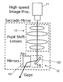
- the imaging unit 1 includes a camera 11 and a drive unit 12. Furthermore, the imaging unit 1 includes a pupil transfer unit 13. A specific configuration example of the imaging unit 1 is shown in FIG.
- the drive unit 12 includes a specular optical system that changes the viewing direction of the camera 11 between a pan direction and a tilt direction. More specifically, as shown in FIG. 2, the drive unit 12 includes a pan mirror 121 and a tilt mirror 122. Each of the pan mirror 121 and the tilt mirror 122 can be rotated in a pan direction or a tilt direction around a predetermined axis by a driving means (not shown) such as a control motor. In the present embodiment, the pan angle and the tilt angle can be controlled by a control unit (not shown). Furthermore, in the present embodiment, the actual pan angle and tilt angle can be acquired and fed back to the control unit side.
- a driving means such as a control motor.
- the pan angle and the tilt angle can be controlled by a control unit (not shown).
- the actual pan angle and tilt angle can be acquired and fed back to the control unit side.
- the drive unit 12 of the present embodiment is controlled by a control unit (not shown) so that the line-of-sight direction of the camera 11 is directed to the portion extracted as a difference by the difference extraction unit 5.
- the pupil transfer unit 13 includes a pupil transfer optical system shown in FIG.
- the pupil transfer unit 13 transfers the pupil position of the camera 11 between the pan mirror 121 and the tilt mirror 122.
- the polar coordinate calculation unit 2 includes a line-of-sight direction acquisition unit 21, a viewpoint position acquisition unit 22, and a coordinate conversion unit 23. Furthermore, the polar coordinate calculation unit 2 of the present embodiment includes a quantization unit 24.
- the line-of-sight direction acquisition unit 21 is configured to acquire the line-of-sight direction in the camera 11. Specifically, the line-of-sight direction acquisition unit 21 captures information on the tilt angles of the pan mirror 121 and the tilt mirror 122 in the drive unit 12 (preferably actual angles but may be control command values). 1 (or a control unit not shown), and the line-of-sight direction is calculated.
- the viewpoint position acquisition unit 22 is configured to acquire the viewpoint position in the camera 11. Specifically, the viewpoint position acquisition unit 22 acquires information about the tilt angles of the pan mirror 121 and the tilt mirror 122 in the drive unit 12 from the imaging unit 1 and calculates the viewpoint position, as in the gaze direction acquisition unit 21. It is supposed to be.
- the coordinate conversion unit 23 converts pixel position information in the background image or the actual image into polar coordinate information in a fixed coordinate system (so-called world coordinate system) using the acquired line-of-sight direction and viewpoint position.
- the conversion to polar coordinate information in the coordinate conversion unit 23 is (1) processing for converting pixel position information in a background image or real image into virtual position information that is position information of the pixel on a virtual image in a virtual camera with a fixed viewpoint; and (2) virtual position It is executed by a process that converts information into polar coordinate information in a fixed coordinate system.
- the quantization unit 24 quantizes the polar coordinate information obtained by the coordinate conversion unit 23.
- the quantization unit 24 is configured to increase the angle range as a quantization unit as the line-of-sight direction in the camera 11 deviates from the reference direction in the fixed coordinate system.
- the polar coordinate calculation unit 2 can be configured by, for example, a combination of computer hardware and software.
- the recording unit 3 is configured to record the correspondence between the color information of the pixel in the background image and the polar coordinate information of the pixel.
- the recording unit 3 of the present embodiment uses polar coordinate information quantized by the quantization unit 24 as polar coordinate information of pixels to be recorded in the recording unit 3.
- the recording unit 3 is, for example, a volatile or non-volatile memory that can be used by a computer, but there is no restriction on a specific recording medium.
- the recording unit 3 may be a recording device that can be used by a computer via a network.
- the color space of the pixel is not particularly limited, and an appropriate color space such as RGB or HSV can be used as necessary.
- the color space may be only luminance information, or may be only color information other than luminance information as necessary.
- the target background extraction unit 4 uses the polar coordinate information of the pixels in the actual image to identify the background image in the angle region corresponding to the actual image as the target background.
- the difference extraction unit 5 extracts a difference between them by comparing the actual image with the target background.
- the background update unit 6 is configured to specify a portion of the actual image that has not been determined to be a difference by the difference extraction unit 5 as a new background image and update the color information of the pixels of the background image in the recording unit 3. Yes.
- This tracking system includes a computer 100.
- this computer 100 that is, a combination of hardware and software
- a polar coordinate calculation unit 2 a recording unit 3
- a target background extraction unit 4 a difference extraction unit 5
- a background update unit a computer 100.
- the tilt angle (pan angle and tilt angle) of the pan mirror 121 and the tilt mirror 122 is controlled, so You can adjust the line of sight (ie, track).
- the actual tilt angles of the pan mirror 121 and the tilt mirror 122 are acquired by a sensor (not shown), returned to the computer 100, and can be used by the polar coordinate calculation unit 2, for example.
- Step SA-1 in FIG. 4 In the background difference extraction method of the present embodiment, first, a process of registering a background image that is an image not including an object is performed. A specific example of the background image registration process will be described in detail with reference to FIG.
- the background images corresponding to all gaze direction ranges are acquired. That is not essential.
- the acquired background image information (pixel information and pixel position information on the image) is sent to the coordinate conversion unit 23.
- Step SB-2 in FIG. 5 the actual tilt angles of the pan mirror 121 and the tilt mirror 122 (when acquiring the background image) are sent from the drive unit 12 to the line-of-sight direction acquisition unit 21 and the viewpoint position acquisition unit 22.
- the line-of-sight acquisition unit 21 and the viewpoint position acquisition unit 22 calculate the line-of-sight direction and the viewpoint position using information on the tilt angles of the pan mirror 121 and the tilt mirror 122.
- an instruction value of the tilt angle thereto instead of the actual tilt angles of the pan mirror 121 and the tilt mirror 122, it is also possible to use an instruction value of the tilt angle thereto.
- an improvement in tracking accuracy can be expected by using an actual inclination angle.
- a method of calculating the gaze direction and the viewpoint position using the information on the tilt angles of the pan mirror 121 and the tilt mirror 122 in the gaze direction acquisition unit 21 and the viewpoint position acquisition unit 22 will be described.
- FIG. 6 shows the positional relationship between the camera 11, the pan mirror 121, and the tilt mirror 122 with respect to a fixed coordinate system (sometimes referred to as world coordinates).
- the viewing direction of the camera 11 can be controlled by the pan mirror 121 and the tilt mirror 122.
- the pupil transfer unit 13 optically transfers the pupil position of the camera 11 to the middle of these mirrors. Accordingly, it is possible to reduce the size of the drive unit 12 while maintaining a sufficient angle of view, and it is possible to perform high-speed line-of-sight control.
- the pupil transferred between the pan mirror 121 and the tilt mirror 122 by the pupil transfer unit 13 can be seen at the position indicated by reference sign p in FIG.
- each rotation matrix R t R p can be expressed as follows.
- viewpoint position p described above can be written as follows.
- the viewpoint position acquisition unit 22 can calculate the viewpoint position from the information on the tilt angles of the pan mirror 121 and the tilt mirror 122 (that is, the viewing direction ⁇ c and ⁇ c of the camera) using this calculation. That is, as described above, the position (viewpoint position) of the pupil transferred by the pupil transfer unit 13 varies as the pan angle or tilt angle is changed.
- the line-of-sight direction acquisition unit 21 can easily acquire the line-of-sight direction (that is, ⁇ c and ⁇ c ) of the camera 11 using the rotation angle of the pan / tilt mirror.
- Step SB-3 in FIG. 5 the coordinate conversion unit 23 uses the information on the line-of-sight direction and viewpoint position of the camera 11 (that is, ⁇ c and ⁇ c ) to convert pixel position information in the background image in the fixed coordinate system (X, Y, Z). Convert to polar coordinate information.
- ⁇ c and ⁇ c the information on the line-of-sight direction and viewpoint position of the camera 11
- the focal length of the camera 11 is f
- the image plane is ⁇ .
- the following camera coordinate system hereinafter referred to as “virtual camera coordinate system” when the translation component in the viewpoint movement is assumed to be 0 is considered.
- the image plane corresponding to this virtual camera coordinate system (the virtual image on the virtual camera) is denoted by ⁇ ′.
- a point on the background is set as P, and a plane passing through the point P and parallel to the planes ⁇ and ⁇ ′ is set as ⁇ (see FIG. 7A).
- Steps SC-1 and SC-2 in FIG. 8 the polar coordinate calculation procedure will be described with reference to the flowchart of FIG. A point where the point P is projected onto the plane ⁇ is (u, v), and a point where the point P is projected onto the plane ⁇ ′ is (u ′, v ′). However, the origins of (u, v) and (u ′, v ′) are on z c and z ′ c , respectively.
- Step SC-3 in FIG. 8 When the point (u ′, v ′) calculated in this way is used, the polar coordinate display angle ( ⁇ , ⁇ ) of the point P in the XYZ fixed coordinate system is expressed as follows (FIG. 7B).
- the pixel position (u, v) in the camera image obtained with an arbitrary line of sight can be expressed by the polar coordinate angle ( ⁇ , ⁇ ) using the equations (5) and (6).
- L the polar coordinate angle
- weak perspective projection reference: J. Aloimonos: “Perspective approximations", Image and Vision Computing, vol. 8, no. 3, pp. 179.192 (1990)
- weak perspective projection all objects are orthographically projected once onto a plane of distance L.
- L the plane of distance
- polar coordinate information can be acquired for each pixel of the background image. Since the above process can be performed in the same manner for all background images, polar coordinate information for all background images can be acquired.
- the quantization unit 24 performs a process of quantizing the polar coordinate information obtained by the coordinate conversion unit 23.
- the quantization unit 24 performs the quantization so that the angle range as the quantization unit is increased as the line-of-sight direction in the camera 11 deviates from the reference direction (Z-axis direction in this example) in the fixed coordinate system.
- the reference direction Z-axis direction in this example
- ⁇ u and ⁇ v could be defined as follows, for example.
- FIG. 9 shows a conceptual diagram of the quantization unit when quantization is performed as described above.
- the amount of pixels that the pan angle per unit takes up increases, so if the quantization unit is written with a constant width, the rectangular image will be transformed into a “ball shape”.
- m and n can take negative values.
- reference to empty data is performed by appropriately interpolating the data. It is preferable to prevent this.
- Step SB-4 in FIG. 5 the recording unit 3 records the correspondence between the color information of the pixel in the background image and the polar coordinate information of the pixel.
- the recording unit 3 uses the polar coordinate information quantized by the quantization unit 24 as the polar coordinate information of the pixel.
- Step SA-2 in FIG. 4 Next, actual image information is calculated.
- the procedure for calculating actual image information will be described with reference to the flowchart of FIG.
- Step SD-1 in FIG. 10 First, an actual image that is an image including an object is acquired by the imaging unit 1.
- the image acquisition method itself is the same as that for the background image. However, when the line of sight tracks the object, it is desirable to perform the following difference extraction process for each real image acquisition.
- Step SD-2 in FIG. 10 On the other hand, the line-of-sight direction and viewpoint position of the camera 11 are acquired by the line-of-sight direction acquisition unit 21 and the viewpoint position acquisition unit 22. This may be the same as in the case of the background image.
- Step SD-3 in FIG. 10 the coordinate conversion unit 23 converts the pixel position information in the actual image into polar coordinate information in the fixed coordinate system using the information on the viewing direction and the viewpoint position of the camera 11. This coordinate conversion process can also be performed in the same manner as the background image described above.
- the obtained polar coordinate information is sent to the target background extraction unit 4.
- the target background extraction unit 4 specifies a background image in an angle region corresponding to the actual image as the target background using the polar coordinate information of the pixels in the actual image. More specifically, the target background extraction unit 4 specifies a background image in a region corresponding to a region where the real image is captured based on polar coordinate information (actually quantized) of the real image. Can do. Accordingly, the target background extraction unit 4 can send polar coordinate information specifying a range corresponding to the actual image to the recording unit 3 and can specify or acquire an image of the target background (that is, pixel information) corresponding to the polar coordinate information. .
- Step SA-4 in FIG. 4 the difference extraction unit 5 extracts the difference between them by comparing the actual image and the target background. Since the real image and the target background are images of the same region in the real space (which may be referred to as a plane plane in FIG. 7A), the information (color information) between these pixels should be compared. Thus, the background difference can be extracted.
- a method based on the pixel position on the image plane that is, a method performed in the image space
- a method based on the pixel position on the polar coordinate that is, in the polar coordinate space. How to do).
- the pixel position on the image plane is used as a reference
- the correspondence between the polar coordinate and the pixel position on the image plane is used, and the pixel position is used as a reference.
- the pixels at the position can be compared.
- the pixels corresponding to the same polar coordinate may be compared.
- target extraction using image features can also be performed.
- Step SA-5 in FIG. 4 the difference extraction unit 5 sends the obtained difference information (that is, position information of the object) to a control unit (not shown).
- the control unit controls the drive unit 12 so that the line-of-sight direction of the camera 11 faces the position of the object. Thereby, the object can be tracked by the camera 11. If each of the processes described above is sufficiently fast, it is possible to place the moving object at substantially the center of the camera image.
- Step SA-6 in FIG. 4 A portion other than the difference extracted by the difference extraction unit 5 can be used as information representing the background (that is, background information). Therefore, the difference extraction unit 5 of the present embodiment sends background information to the background update unit 6.
- the background information includes position information corresponding to the background (quantized polar coordinate information in this example) and pixel color information at that position.
- the background update unit 6 can use the background information to specify and update the background pixel information in the recording unit 3 using polar coordinate information. As a result, the background information can be updated to the latest, so that the accuracy of extracting the background difference can be improved.
- the background information need not be updated every time a background difference is extracted, but can be updated at predetermined time intervals. Alternatively, the background information update process based on background difference extraction can be omitted. For example, all background information may be reacquired and updated every predetermined time.
- Step SA-7 in FIG. 4 Next, when a new real image is acquired by the camera 11, the process returns to step SA-2 and the above-described processing is repeated. Otherwise, the process is terminated.
- the apparatus of this embodiment can be applied in various fields such as medical care, factory automation, and robot vision.
- the apparatus of the second embodiment is different from the apparatus of the first embodiment in that a blur generation unit 7 is additionally provided.
- the blur generation unit 7 specifies a plurality of target backgrounds along the direction in which the line-of-sight direction moves, and combines the specified target backgrounds to generate a synthesis target background having a blur. It is a functional element.
- the difference extraction unit 5 of the second embodiment is configured to extract the difference by comparing the actual image and the synthesis target background.
- the background update unit 6 is omitted and sequential background update is not performed. Therefore, the background image recorded in the recording unit 3 is an image of the entire background acquired initially (or an image of the entire background reacquired thereafter).
- Motion blur is image blur caused by movement of a subject or the camera itself during exposure. If shooting is performed so that the tracking target is always shot at a fixed position in the image, depending on the moving speed of the target, a large amount of blur (that is, blur) may occur in the landscape portion even if the exposure time is shortened.
- the background pixel information recorded in the recording unit 3 is normally premised on a stationary state, and therefore there is no blur in the background image. Therefore, when such blurring occurs, it is generally difficult to accurately extract the background difference. Therefore, it is conceivable to blur the background image by image processing.
- blur removal using the previously proposed blur kernel reference: P. Hansen and J. N. D.
- a “background image including a blur” is synthesized using a condition that the line-of-sight direction of the camera 11 is known, and background difference is performed.
- An image obtained from the camera is obtained as a sum of light incident on each image receiving element during exposure. That is, an image I (t) obtained by exposure for ⁇ t seconds from time t can be expressed by the following equation.
- i ( ⁇ c , ⁇ c ) represents an image at rest in the line-of-sight direction ( ⁇ c , ⁇ c ).
- I ⁇ the number of samplings during exposure.
- ( ⁇ c [k], ⁇ c [k]) represents the line-of-sight direction at the time of the k-th sampling (time t + (k / n) ⁇ t).
- This process is “a process of generating a synthesis target background I ⁇ having blur by specifying a plurality of target backgrounds along the direction in which the line-of-sight direction moves and combining the specified target backgrounds” It corresponds to.
- a background image including motion blur can be synthesized based on the entire visual field background.
- the motion blur can be generated in the background image, it can be expected to improve the accuracy of difference extraction.
- the number of images to be combined for blur generation can basically be determined by the moving speed of the line of sight. That is, the sampling interval of image acquisition and the exposure time ⁇ t of the camera are normally constant, but the number of images acquired within the constant exposure time ⁇ t is used to determine the blur generation to be used to move the line of sight Can be determined by speed. For example, when the line-of-sight movement speed is low, it is conceivable to synthesize some images by thinning out rather than using all acquired images within ⁇ t. Thus, the number of images used for blur generation can be changed according to the line-of-sight movement speed.
- each of the above-described components only needs to exist as a functional block, and does not have to exist as independent hardware.
- a mounting method hardware or computer software may be used.
- one functional element in the present invention may be realized by a set of a plurality of functional elements, and a plurality of functional elements in the present invention may be realized by one functional element.
- the functional elements may be arranged at physically separated positions.
- the functional elements may be connected by a network. It is also possible to realize functions or configure functional elements by grid computing or cloud computing.
- the present invention is not limited to this, and the present invention can be applied to any camera whose viewpoint is movable. It is believed that there is.
Landscapes
- Engineering & Computer Science (AREA)
- Computer Vision & Pattern Recognition (AREA)
- Physics & Mathematics (AREA)
- General Physics & Mathematics (AREA)
- Theoretical Computer Science (AREA)
- Multimedia (AREA)
- Signal Processing (AREA)
- Image Analysis (AREA)
- Image Processing (AREA)
- Closed-Circuit Television Systems (AREA)
Abstract
視点が移動するカメラで取得した画像を用いた背景差分の取得を可能にするための技術が提供される。まず、カメラ11により、対象物を含まない画像である背景画像を取得する。カメラ11の視線方向及び視点位置の情報を用いて、背景画像における画素の位置情報を、固定座標系における極座標情報に変換する。背景画像における画素の色情報と、当該画素の極座標情報との対応関係を記録部3に記録する。つぎに、カメラ11により、対象物を含む画像である実画像を取得する。カメラ11の視線方向及び視点位置の情報を用いて、実画像における画素の位置情報を、固定座標系における極座標情報に変換する。実画像における画素の極座標情報を用いて、実画像に対応する角度領域での背景画像を対象背景として特定する。実画像と対象背景とを比較することによって、それらの間の差分を抽出する。
Description
本発明は、画像データどうしを比較することによって背景差分を抽出するための技術に関するものである。
被写体を継続的に撮影するためには、カメラの視線を対象に向け続ける必要がある。多くの場合この作業は撮影者が手動で行うが、ボールの跳躍のような高速かつ不規則な運動に完璧に追従するのは難しい。このため、カメラの視線方向を機械で自動制御するシステム(いわゆるアクティブビジョン;下記非特許文献1参照)の研究は様々な分野で盛んとなっている。
通常のアクティブビジョンの技術では、カメラ自体を駆動雲台に取り付けて動かしているため、視線方向の移動についての応答速度が遅い。これでは、急激な加速度変化を含む運動対象(例えば球技で用いられているボール)をトラッキングすることは難しい。高速カメラのフレームレートが、速いものでは100万fpsに達する事や、GPUによって画像処理が高速化されている現状を考えると、視線制御速度は、様々なトラッキングシステムにおいて速度面でのボトルネックとなっていると言える。
この問題を解決するために、カメラ前方に配置した小型駆動鏡面によって高速にカメラの視線変更を行うサッカードミラー(Saccade Mirror)と呼ばれる光学系が提案されている(下記非特許文献2参照)。この技術では、2軸のガルバノミラーを用いることによって、高速な視線変更ができるようになっている。もし、制御系において、常に画面中心で対象物をとらえるように視線の制御ができれば、他に類を見ないダイナミックな撮像が可能になると考えられる。
ところで、対象物をトラッキングするには、画像中の対象物を抽出し、その方向にカメラの視線を向ける必要がある。画像中の対象物を抽出する方法としては、例えば:
(1)画像中の特徴量を抽出した後、事前学習で得た学習データとの比較によって画像中の対象物を特定する方法;
(2)背景画像をあらかじめ取得しておき、対象物を含む画像(実画像)との比較によって対象物を特定する方法(いわゆる背景差分法)
などが存在する。前記(1)の方法は、背景画像の取得が不要であるという利点はあるが、画像処理の時間が長くなるので、実時間での対象物特定には不向きである。また、この方法は、学習データの内容にもよるが、対象物の特定精度も不十分となりがちである。
(1)画像中の特徴量を抽出した後、事前学習で得た学習データとの比較によって画像中の対象物を特定する方法;
(2)背景画像をあらかじめ取得しておき、対象物を含む画像(実画像)との比較によって対象物を特定する方法(いわゆる背景差分法)
などが存在する。前記(1)の方法は、背景画像の取得が不要であるという利点はあるが、画像処理の時間が長くなるので、実時間での対象物特定には不向きである。また、この方法は、学習データの内容にもよるが、対象物の特定精度も不十分となりがちである。
前記(2)の背景差分法は、高速な対象物特定が可能であるという利点がある。しかしながら、従来から提案されている背景差分法(例えば下記非特許文献3及び4)は、視点固定カメラで得られた画像を前提としている。これらの技術は、視点が動くカメラに直接適用することは難しいと考えられる。
J. Aloimonos, I. Weiss and A. Bandyopadhyay: "Active Vision", Int'l Journal of Computer Vision, vol. 1, no. 4, pp. 333.356 (1988).
K. Okumura, H. Oku and M. Ishikawa: "High-Speed Gaze Controller for Millisecond-order Pan/tilt Camera", Proc. of IEEE Int'l Conf. on Robotics and Automation, pp. 6186. 6191 (2011).
T. Wada and T. Matsuyama: "Appearance Sphere: Background model for pan-tilt-zoom camera", Proc. of 13th Int'l Conf. of Pattern Recognition, pp. A718.722 (1996).
K. Yachi, T. Wada and T. Matsuyama: "Human Head Tracking using Adaptive Appearance Model with a Fixed-viewpoint Pan-tilt-zoom Camera", Proc. of IEEE Intl' Conf. on Automatic Face and Gesture Recognition, pp. 150.155 (2000).
本発明は、前記の状況に鑑みてなされたものである。本発明は、視点が移動するカメラで取得した画像を用いた背景差分の取得を可能にするための技術を提供することを目的としている。
前記した課題を解決する手段は、以下の項目のように記載できる。
(項目1)
視線方向及び視点位置が移動可能なカメラで得られた画像を用いて背景差分を抽出するための装置であって、
撮像部と、極座標算出部と、記録部と、対象背景抽出部と、差分抽出部とを備えており、
前記撮像部は、カメラと、駆動部とを備えており、
前記カメラは、対象物を含まない画像である背景画像、あるいは、対象物を含む画像である実画像を取得できる構成となっており、
前記駆動部は、前記カメラの視線方向及び視点位置を変更できる構成となっており、
前記極座標算出部は、視線方向取得部と、視点位置取得部と、座標変換部とを備えており、
前記視線方向取得部は、前記カメラにおける視線方向を取得する構成となっており、
前記視点位置取得部は、前記カメラにおける視点位置を取得する構成となっており、
前記座標変換部は、取得された前記視線方向及び視点位置を用いて、前記背景画像あるいは前記実画像における画素の位置情報を、固定座標系における極座標情報に変換する構成となっており、
前記記録部は、前記背景画像における画素の色情報と、当該画素の極座標情報との対応関係を記録する構成となっており、
前記対象背景抽出部は、前記実画像における画素の極座標情報を用いて、前記実画像に対応する角度領域での前記背景画像を対象背景として特定する構成となっており、
前記差分抽出部は、前記実画像と前記対象背景とを比較することによって、それらの間の差分を抽出する構成となっている
背景差分抽出装置。
視線方向及び視点位置が移動可能なカメラで得られた画像を用いて背景差分を抽出するための装置であって、
撮像部と、極座標算出部と、記録部と、対象背景抽出部と、差分抽出部とを備えており、
前記撮像部は、カメラと、駆動部とを備えており、
前記カメラは、対象物を含まない画像である背景画像、あるいは、対象物を含む画像である実画像を取得できる構成となっており、
前記駆動部は、前記カメラの視線方向及び視点位置を変更できる構成となっており、
前記極座標算出部は、視線方向取得部と、視点位置取得部と、座標変換部とを備えており、
前記視線方向取得部は、前記カメラにおける視線方向を取得する構成となっており、
前記視点位置取得部は、前記カメラにおける視点位置を取得する構成となっており、
前記座標変換部は、取得された前記視線方向及び視点位置を用いて、前記背景画像あるいは前記実画像における画素の位置情報を、固定座標系における極座標情報に変換する構成となっており、
前記記録部は、前記背景画像における画素の色情報と、当該画素の極座標情報との対応関係を記録する構成となっており、
前記対象背景抽出部は、前記実画像における画素の極座標情報を用いて、前記実画像に対応する角度領域での前記背景画像を対象背景として特定する構成となっており、
前記差分抽出部は、前記実画像と前記対象背景とを比較することによって、それらの間の差分を抽出する構成となっている
背景差分抽出装置。
(項目2)
前記座標変換部における、前記極座標情報への変換は、
前記背景画像あるいは前記実画像における画素の位置情報を、視点が固定された仮想カメラにおける仮想画像上での、当該画素の位置情報である仮想位置情報に変換する処理と、
前記仮想位置情報を、前記固定座標系における極座標情報に変換する処理と
によって行われる構成となっている
項目1に記載の背景差分抽出装置。
前記座標変換部における、前記極座標情報への変換は、
前記背景画像あるいは前記実画像における画素の位置情報を、視点が固定された仮想カメラにおける仮想画像上での、当該画素の位置情報である仮想位置情報に変換する処理と、
前記仮想位置情報を、前記固定座標系における極座標情報に変換する処理と
によって行われる構成となっている
項目1に記載の背景差分抽出装置。
(項目3)
さらに量子化部を備えており、
前記量子化部は、前記座標変換部で得られた前記極座標情報を量子化する構成とされており、
さらに、前記量子化部は、前記カメラにおける視線方向が前記固定座標系における基準方向からずれるほど、量子化単位としての角度範囲を増やす構成とされており、
前記記録部は、前記画素の極座標情報として、量子化された前記極座標情報を用いる構成とされている
項目1又は2に記載の背景差分抽出装置。
さらに量子化部を備えており、
前記量子化部は、前記座標変換部で得られた前記極座標情報を量子化する構成とされており、
さらに、前記量子化部は、前記カメラにおける視線方向が前記固定座標系における基準方向からずれるほど、量子化単位としての角度範囲を増やす構成とされており、
前記記録部は、前記画素の極座標情報として、量子化された前記極座標情報を用いる構成とされている
項目1又は2に記載の背景差分抽出装置。
(項目4)
さらに、ブラー生成部を備えており、
前記ブラー生成部は、前記対象背景を、前記視線方向が移動する方向に沿って複数枚特定し、特定された複数枚の前記対象背景を合成することによって、ブラーを有する合成対象背景を生成する構成とされており、
前記差分抽出部は、前記実画像と前記合成対象背景とを比較することによって、前記差分を抽出する構成とされている
項目1~3のいずれか1項に記載の背景差分抽出装置。
さらに、ブラー生成部を備えており、
前記ブラー生成部は、前記対象背景を、前記視線方向が移動する方向に沿って複数枚特定し、特定された複数枚の前記対象背景を合成することによって、ブラーを有する合成対象背景を生成する構成とされており、
前記差分抽出部は、前記実画像と前記合成対象背景とを比較することによって、前記差分を抽出する構成とされている
項目1~3のいずれか1項に記載の背景差分抽出装置。
(項目5)
前記カメラの視線方向は、パン方向角度とチルト方向角度とによってあらわされている
項目1~4のいずれか1項に記載の背景差分抽出装置。
前記カメラの視線方向は、パン方向角度とチルト方向角度とによってあらわされている
項目1~4のいずれか1項に記載の背景差分抽出装置。
(項目6)
前記駆動部は、前記カメラの視線方向をパン方向とチルト方向とに変化させる鏡面光学系を備えている
項目1~5のいずれか1項に記載の背景差分抽出装置。
前記駆動部は、前記カメラの視線方向をパン方向とチルト方向とに変化させる鏡面光学系を備えている
項目1~5のいずれか1項に記載の背景差分抽出装置。
(項目7)
さらに、背景更新部を備えており、
前記背景更新部は、前記実画像のうち、前記差分抽出部において前記差分とされなかった部分を新たな背景画像として特定して、前記記録部における前記背景画像における画素の色情報を更新する構成とされている
項目1~6のいずれか1項に記載の背景差分抽出装置。
さらに、背景更新部を備えており、
前記背景更新部は、前記実画像のうち、前記差分抽出部において前記差分とされなかった部分を新たな背景画像として特定して、前記記録部における前記背景画像における画素の色情報を更新する構成とされている
項目1~6のいずれか1項に記載の背景差分抽出装置。
(項目8)
前記駆動部は、前記差分抽出部によって差分として抽出された部分に前記カメラの視線方向を向ける構成とされている
項目1~7のいずれか1項に記載の背景差分抽出装置。
前記駆動部は、前記差分抽出部によって差分として抽出された部分に前記カメラの視線方向を向ける構成とされている
項目1~7のいずれか1項に記載の背景差分抽出装置。
(項目9)
視線方向及び視点位置が移動可能なカメラで得られた画像を用いて背景差分を抽出するための方法であって、
前記カメラにより、対象物を含まない画像である背景画像を取得するステップと、
前記カメラの視線方向及び視点位置の情報を用いて、前記背景画像における画素の位置情報を、前記固定座標系における極座標情報に変換するステップと、
前記背景画像における画素の色情報と、当該画素の極座標情報との対応関係を記録部に記録するステップと、
前記カメラにより、対象物を含む画像である実画像を取得するステップと、
前記カメラの視線方向及び視点位置の情報を用いて、前記実画像における画素の位置情報を、固定座標系における極座標情報に変換するステップと、
前記実画像における画素の極座標情報を用いて、前記実画像に対応する角度領域での前記背景画像を対象背景として特定するステップと、
前記実画像と前記対象背景とを比較することによって、それらの間の差分を抽出するステップと
を備えることを特徴とする背景差分抽出方法。
視線方向及び視点位置が移動可能なカメラで得られた画像を用いて背景差分を抽出するための方法であって、
前記カメラにより、対象物を含まない画像である背景画像を取得するステップと、
前記カメラの視線方向及び視点位置の情報を用いて、前記背景画像における画素の位置情報を、前記固定座標系における極座標情報に変換するステップと、
前記背景画像における画素の色情報と、当該画素の極座標情報との対応関係を記録部に記録するステップと、
前記カメラにより、対象物を含む画像である実画像を取得するステップと、
前記カメラの視線方向及び視点位置の情報を用いて、前記実画像における画素の位置情報を、固定座標系における極座標情報に変換するステップと、
前記実画像における画素の極座標情報を用いて、前記実画像に対応する角度領域での前記背景画像を対象背景として特定するステップと、
前記実画像と前記対象背景とを比較することによって、それらの間の差分を抽出するステップと
を備えることを特徴とする背景差分抽出方法。
(項目10)
視線方向及び視点位置が移動可能なカメラで得られた画像を用いて背景差分を抽出するためのコンピュータプログラムであって、
対象物を含まない画像である背景画像をカメラに取得させるステップと、
前記カメラの視線方向及び視点位置の情報を用いて、前記背景画像における画素の位置情報を、固定座標系における極座標情報に変換するステップと、
前記背景画像における画素の色情報と、当該画素の極座標情報との対応関係を記録部に記録するステップと、
対象物を含む画像である実画像を前記カメラに取得させるステップと、
前記カメラの視線方向及び視点位置の情報を用いて、前記実画像における画素の位置情報を、前記固定座標系における極座標情報に変換するステップと、
前記実画像における画素の極座標情報を用いて、前記実画像に対応する角度領域での前記背景画像を対象背景として特定するステップと、
前記実画像と前記対象背景とを比較することによって、それらの間の差分を抽出するステップと
をコンピュータに実行させるためのコンピュータプログラム。
視線方向及び視点位置が移動可能なカメラで得られた画像を用いて背景差分を抽出するためのコンピュータプログラムであって、
対象物を含まない画像である背景画像をカメラに取得させるステップと、
前記カメラの視線方向及び視点位置の情報を用いて、前記背景画像における画素の位置情報を、固定座標系における極座標情報に変換するステップと、
前記背景画像における画素の色情報と、当該画素の極座標情報との対応関係を記録部に記録するステップと、
対象物を含む画像である実画像を前記カメラに取得させるステップと、
前記カメラの視線方向及び視点位置の情報を用いて、前記実画像における画素の位置情報を、前記固定座標系における極座標情報に変換するステップと、
前記実画像における画素の極座標情報を用いて、前記実画像に対応する角度領域での前記背景画像を対象背景として特定するステップと、
前記実画像と前記対象背景とを比較することによって、それらの間の差分を抽出するステップと
をコンピュータに実行させるためのコンピュータプログラム。
このコンピュータプログラムは、適宜な記録媒体(例えばCD-ROMやDVDディスクのような光学的な記録媒体、ハードディスクやフレキシブルディスクのような磁気的記録媒体、あるいはMOディスクのような光磁気記録媒体)に格納することができる。このコンピュータプログラムは、インターネットなどの通信回線を介して伝送されることができる。
本発明によれば、視点が移動するカメラで取得した画像を用いた背景差分の取得が可能となる。したがって、例えば、取得した背景差分を対象物とみなして、この対象物を追跡するためにカメラの視線制御を行うことが可能となる。
以下、添付図面を参照しながら、本発明の第1実施形態に係る背景差分抽出装置について説明する。本実施形態の装置は、後述する対象物トラッキングシステムにおいて用いられるものである。
(第1実施形態の構成)
本実施形態の背景差分抽出装置は、図1に示されるように、撮像部1と、極座標算出部2と、記録部3と、対象背景抽出部4と、差分抽出部5とを有している。さらに、この装置は、背景更新部6を有している。
本実施形態の背景差分抽出装置は、図1に示されるように、撮像部1と、極座標算出部2と、記録部3と、対象背景抽出部4と、差分抽出部5とを有している。さらに、この装置は、背景更新部6を有している。
撮像部1は、カメラ11と、駆動部12とを備えている。さらに撮像部1は、瞳転送部13を備えている。撮像部1の具体的構成例を図2に示す。
カメラ11は、対象物のトラッキングのために適切なフレームレートで画像を取得する構成となっている。例えば、対象物が高速に移動する場合は、1フレーム当たり1msのサイクルでデジタル画像を取得するものを用いることができるが、これはあくまで一例であり、用途に応じて異なるフレームレートを使用することができる。カメラ11の画素数は、トラッキングの目的に即して決定することができ、原理的には特段の制約はない。カメラ11の視線方向を、図2において矢印で示している。後述するように、カメラ11は、対象物を含まない画像である背景画像、あるいは、対象物を含む画像である実画像を取得できる構成となっている。すなわち、カメラ11は、背景画像情報の登録時には背景画像を撮影し、対象物のトラッキングの際には実画像(対象物を含む画像)を撮影するものである。もちろん、本実施形態において、背景画像撮影用のカメラと実画像撮影用のカメラとを別々に備えることも可能である。なお、カメラ11としては、可視光カメラに限らず、赤外光やその他の波長域の電磁波(テラヘルツ波やミリ波を含む)を撮像するカメラであってもよい。要するに、カメラ11としては、デジタル画像を取得できるものであればよく、いわゆるレンジファインダであってもよい。また、カメラ11としては、単一波長の光を撮像するカメラ(モノクロカメラ)であってもよい。この場合、得られた画像の画素値は輝度値のみとなる。本明細書では、画素の輝度値自体も「画素の色情報」の一例に対応するものとする。
駆動部12は、カメラ11の視線方向をパン方向とチルト方向とに変化させる鏡面光学系を備えている。より具体的には、図2に示されるように、駆動部12は、パンミラー121とチルトミラー122とを備えている。パンミラー121及びチルトミラー122は、いずれも、図示しない駆動手段、例えば制御モータにより、所定の軸を中心として、パン方向あるいはチルト方向にそれぞれ回動できるようになっている。また、本実施形態では、図示しない制御部により、パン角度及びチルト角度を制御できるようになっている。さらに本実施形態では、実際のパン角度及びチルト角度を取得して、制御部側にフィードバックすることができるようになっている。
後述するように、瞳転送部13により転送された瞳の位置(つまり視点位置)は、パン角度あるいはチルト角度の変更に伴って変動する。これにより、駆動部12は、カメラ11の視線方向及び視点位置を変更できる構成となっている。なお、本明細書において、カメラ11の視線方向は、パン方向角度とチルト方向角度とによって表されるものとする。
さらに、本実施形態の駆動部12は、差分抽出部5によって差分として抽出された部分にカメラ11の視線方向を向けるように、図示しない制御部によって制御されるものである。
瞳転送部13は、図2に示す瞳転送光学系により構成されている。瞳転送部13は、パンミラー121とチルトミラー122との間に、カメラ11の瞳位置を転送するようになっている。
極座標算出部2は、視線方向取得部21と、視点位置取得部22と、座標変換部23とを備えている。さらに、本実施形態の極座標算出部2は、量子化部24を備えている。
視線方向取得部21は、カメラ11における視線方向を取得する構成となっている。具体的には、視線方向取得部21は、駆動部12におけるパンミラー121及びチルトミラー122の傾斜角度の情報(実際の角度であることが好ましいが制御指令値であってもよい)を撮像部1(又は図示しない制御部)から取得して、視線方向を算出するようになっている。
視点位置取得部22は、カメラ11における視点位置を取得する構成となっている。具体的には、視点位置取得部22は、視線方向取得部21と同様に、駆動部12におけるパンミラー121及びチルトミラー122の傾斜角度の情報を撮像部1から取得して、視点位置を算出するようになっている。
座標変換部23は、取得された視線方向及び視点位置を用いて、背景画像あるいは実画像における画素の位置情報を、固定座標系(いわゆるワールド座標系)における極座標情報に変換するものである。
本実施形態では、座標変換部23における極座標情報への変換が、
(1)背景画像あるいは実画像における画素の位置情報を、視点が固定された仮想カメラにおける仮想画像上での、当該画素の位置情報である仮想位置情報に変換する処理;及び
(2)仮想位置情報を、固定座標系における極座標情報に変換する処理
によって実行されるようになっている。
(1)背景画像あるいは実画像における画素の位置情報を、視点が固定された仮想カメラにおける仮想画像上での、当該画素の位置情報である仮想位置情報に変換する処理;及び
(2)仮想位置情報を、固定座標系における極座標情報に変換する処理
によって実行されるようになっている。
量子化部24は、座標変換部23で得られた極座標情報を量子化するものである。量子化部24は、カメラ11における視線方向が固定座標系における基準方向からずれるほど、量子化単位としての角度範囲を増やす構成とされている。
極座標算出部2における詳しい処理は、本実施形態の動作の説明において詳しく述べる。極座標算出部2は、例えばコンピュータのハードウエア及びソフトウエアの組み合わせにより構成することができる。
記録部3は、背景画像における画素の色情報と、当該画素の極座標情報との対応関係を記録する構成となっている。本実施形態の記録部3は、この記録部3に記録されるべき画素の極座標情報として、量子化部24によって量子化された極座標情報を用いるものとなっている。
記録部3は、例えばコンピュータで利用可能な揮発性あるいは不揮発性メモリであるが、具体的な記録媒体に制約はない。記録部3は、ネットワークを介してコンピュータにより利用可能な記録装置であってもよい。また、画素の色空間としては、特に制約はなく、RGBやHSVなど、必要に応じて適切な色空間を用いることができる。また、色空間としては、輝度情報のみでもよく、また、必要に応じて、輝度情報以外の色彩情報のみであってもよい。
対象背景抽出部4は、実画像における画素の極座標情報を用いて、実画像に対応する角度領域での背景画像を対象背景として特定するものである。
差分抽出部5は、実画像と対象背景とを比較することによって、それらの間の差分を抽出するものである。
背景更新部6は、実画像のうち、差分抽出部5において差分とされなかった部分を新たな背景画像として特定して、記録部3における背景画像の画素の色情報を更新する構成とされている。
本実施形態の背景差分抽出装置におけるさらに具体的な構成は、後述の動作の説明において詳しく述べる。
(第1実施形態の動作)
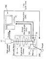
以下、本実施形態の背景差分抽出装置の動作について説明する。以下の説明の前提として、本実施形態の背景差分抽出装置が組み込まれるトラッキングシステムの全体的な構成例を図3により説明する。このトラッキングシステムは、コンピュータ100を備えており、このコンピュータ100(すなわちハードウエア及びソフトウエアの組み合わせ)により、極座標算出部2、記録部3、対象背景抽出部4、差分抽出部5及び背景更新部6の機能が実現されている。また、コンピュータ100の制御部(図示せず)から制御指令を駆動部12に送ることでパンミラー121及びチルトミラー122の傾斜角度(パン角度及びチルト角度)を制御して、追跡対象物200に視線を合わせる(つまり追跡する)ことができるようになっている。さらに、この装置では、パンミラー121及びチルトミラー122の実際の傾斜角度をセンサ(図示せず)により取得して、コンピュータ100に戻し、例えば極座標算出部2により利用できるようになっている。
以下、本実施形態の背景差分抽出装置の動作について説明する。以下の説明の前提として、本実施形態の背景差分抽出装置が組み込まれるトラッキングシステムの全体的な構成例を図3により説明する。このトラッキングシステムは、コンピュータ100を備えており、このコンピュータ100(すなわちハードウエア及びソフトウエアの組み合わせ)により、極座標算出部2、記録部3、対象背景抽出部4、差分抽出部5及び背景更新部6の機能が実現されている。また、コンピュータ100の制御部(図示せず)から制御指令を駆動部12に送ることでパンミラー121及びチルトミラー122の傾斜角度(パン角度及びチルト角度)を制御して、追跡対象物200に視線を合わせる(つまり追跡する)ことができるようになっている。さらに、この装置では、パンミラー121及びチルトミラー122の実際の傾斜角度をセンサ(図示せず)により取得して、コンピュータ100に戻し、例えば極座標算出部2により利用できるようになっている。
以下、図4のフローチャートを参照しながら、本例の背景差分抽出方法を説明する。
(図4のステップSA-1)
本実施形態の背景差分抽出方法では、まず、対象物を含まない画像である背景画像を登録する処理を行う。背景画像登録処理の具体例を、図5を参照して詳しく説明する。
本実施形態の背景差分抽出方法では、まず、対象物を含まない画像である背景画像を登録する処理を行う。背景画像登録処理の具体例を、図5を参照して詳しく説明する。
(図5のステップSB-1)
まず、カメラ11により、背景画像を取得する。ここで、本実施形態では、カメラ11で取得可能な全ての領域における背景の画像(本明細書では「全背景画像」と称する)を取得する。すなわち、本実施形態では、駆動部12によりカメラ11の視線方向を変更できるので、視線方向の最大可変範囲に対応して、カメラ11で取得可能な全背景画像を取得する。ただし、全背景画像を一度に取得する必要はなく、所定の画角で撮影された背景画像ごとに、以降の極座標算出処理や登録処理を行うこととしてもよい。もちろん、全背景画像を取得した後に、以降の処理を行うことも可能である。また、全背景画像は、以降の背景差分抽出処理に使用されると予想される角度範囲(あるいは視線方向範囲)で取得されればよいので、全ての視線方向範囲に対応した背景画像を取得することは必須ではない。取得された背景画像の情報(画素情報及び画像上の画素位置情報)は、座標変換部23に送られる。
まず、カメラ11により、背景画像を取得する。ここで、本実施形態では、カメラ11で取得可能な全ての領域における背景の画像(本明細書では「全背景画像」と称する)を取得する。すなわち、本実施形態では、駆動部12によりカメラ11の視線方向を変更できるので、視線方向の最大可変範囲に対応して、カメラ11で取得可能な全背景画像を取得する。ただし、全背景画像を一度に取得する必要はなく、所定の画角で撮影された背景画像ごとに、以降の極座標算出処理や登録処理を行うこととしてもよい。もちろん、全背景画像を取得した後に、以降の処理を行うことも可能である。また、全背景画像は、以降の背景差分抽出処理に使用されると予想される角度範囲(あるいは視線方向範囲)で取得されればよいので、全ての視線方向範囲に対応した背景画像を取得することは必須ではない。取得された背景画像の情報(画素情報及び画像上の画素位置情報)は、座標変換部23に送られる。
(図5のステップSB-2)
一方、パンミラー121及びチルトミラー122の実際の傾斜角度(背景画像取得時のもの)は、駆動部12から視線方向取得部21及び視点位置取得部22に送られる。視線方向取得部21及び視点位置取得部22では、パンミラー121及びチルトミラー122の傾斜角度の情報を用いて、視線方向及び視点位置を算出する。なお、この算出において、パンミラー121及びチルトミラー122の実際の傾斜角度に代えて、これらへの傾斜角度の指示値を用いることも可能である。ただし、実際の傾斜角度を用いることによりトラッキング精度の向上を期待できる。以下において、視線方向取得部21及び視点位置取得部22における、パンミラー121及びチルトミラー122の傾斜角度の情報を用いた、視線方向及び視点位置の算出方法を説明する。
一方、パンミラー121及びチルトミラー122の実際の傾斜角度(背景画像取得時のもの)は、駆動部12から視線方向取得部21及び視点位置取得部22に送られる。視線方向取得部21及び視点位置取得部22では、パンミラー121及びチルトミラー122の傾斜角度の情報を用いて、視線方向及び視点位置を算出する。なお、この算出において、パンミラー121及びチルトミラー122の実際の傾斜角度に代えて、これらへの傾斜角度の指示値を用いることも可能である。ただし、実際の傾斜角度を用いることによりトラッキング精度の向上を期待できる。以下において、視線方向取得部21及び視点位置取得部22における、パンミラー121及びチルトミラー122の傾斜角度の情報を用いた、視線方向及び視点位置の算出方法を説明する。
(視線方向及び視点位置の算出)
固定座標系(世界座標と呼ぶこともある)に対するカメラ11、パンミラー121及びチルトミラー122の位置関係を図6に示す。前記した通り、パンミラー121及びチルトミラー122によって、カメラ11の視線方向を制御できるようになっている。また、瞳転送部13により、カメラ11の瞳位置を光学的にこれらのミラーの中間に転送するようになっている。これにより充分な画角を保ちつつ、駆動部12の小型化が可能となり、しかも高速な視線方向制御が可能となっている。瞳転送部13によりパンミラー121とチルトミラー122との間に転送された瞳は、対象物から見れば、図6において符号pの位置(つまりパンミラー121により瞳の鏡像となる位置)に見える。この位置は、カメラ11の視点位置と光学的に等価なので、以下の説明では視点として扱う。また、視点を原点として対象物に向く視線方向をzc軸とするカメラ座標系を(xc,yc,zc)と定義する(図6参照)。カメラ座標(xc,yc,zc)と固定座標(X,Y,Z)との変換は、下記式(1)のように表現できる。
固定座標系(世界座標と呼ぶこともある)に対するカメラ11、パンミラー121及びチルトミラー122の位置関係を図6に示す。前記した通り、パンミラー121及びチルトミラー122によって、カメラ11の視線方向を制御できるようになっている。また、瞳転送部13により、カメラ11の瞳位置を光学的にこれらのミラーの中間に転送するようになっている。これにより充分な画角を保ちつつ、駆動部12の小型化が可能となり、しかも高速な視線方向制御が可能となっている。瞳転送部13によりパンミラー121とチルトミラー122との間に転送された瞳は、対象物から見れば、図6において符号pの位置(つまりパンミラー121により瞳の鏡像となる位置)に見える。この位置は、カメラ11の視点位置と光学的に等価なので、以下の説明では視点として扱う。また、視点を原点として対象物に向く視線方向をzc軸とするカメラ座標系を(xc,yc,zc)と定義する(図6参照)。カメラ座標(xc,yc,zc)と固定座標(X,Y,Z)との変換は、下記式(1)のように表現できる。

ここで、計算の便宜上、二つのミラー121及び122の中心間距離をlmとし、瞳転送部13によるカメラ11の瞳の転送先を、チルトミラー122からの光軸上距離がlm/2となる位置とする(図6参照)。さらに、カメラ11とパン・チルトミラー121・122とがなす平面(より具体的には、カメラ11の元々の視点位置と両ミラーの中心点との三点を通る平面)とカメラ座標系上のzc軸とが直交する場合のカメラ座標は、世界座標と一致することになる。
視線がパン・チルト方向にそれぞれθc,φcだけ回転したとき(このときのパン・チルトミラー回転量はそれぞれθc/2,φc/2)における、両座標系の間の変換は前記式(1)と同様の形で表される。ここでRはパンミラーおよびチルトミラーによる視線の回転行列RtRpを用いて
R=RtRp (2)
と書ける。
R=RtRp (2)
と書ける。
ここで、各回転行列RtRpは以下のように表せる。

また前記した視点位置pは、以下のように書ける。

したがって、視点位置取得部22では、この計算を用いて、パンミラー121及びチルトミラー122の傾斜角度の情報(すなわちカメラの視線方向θcとφc)から、視点位置を算出できる。つまり、前記したように、瞳転送部13で転送された瞳の位置(視点位置)は、パン角度あるいはチルト角度の変更に伴って変動する。なお、視線方向取得部21は、パン・チルトミラーの回転角を用いて、カメラ11の視線方向(つまりθcとφc)を簡単に取得できる。
(図5のステップSB-3)
ついで、座標変換部23は、カメラ11の視線方向及び視点位置の情報(つまりθcとφc)を用いて、背景画像における画素の位置情報を、固定座標系(X,Y,Z)における極座標情報に変換する。以下、この変換手順の一例を説明する。
ついで、座標変換部23は、カメラ11の視線方向及び視点位置の情報(つまりθcとφc)を用いて、背景画像における画素の位置情報を、固定座標系(X,Y,Z)における極座標情報に変換する。以下、この変換手順の一例を説明する。
(極座標情報の算出)
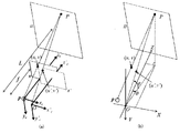
前提として、カメラ11の焦点距離をf、画像平面をπとおく。また図7(a)に示すように、視点移動における並進成分を0と仮定した場合の、下記のカメラ座標系(以下「仮想カメラ座標系」という)を考える。
前提として、カメラ11の焦点距離をf、画像平面をπとおく。また図7(a)に示すように、視点移動における並進成分を0と仮定した場合の、下記のカメラ座標系(以下「仮想カメラ座標系」という)を考える。

この仮想カメラ座標系に対応する画像平面(いわば仮想カメラ上の仮想画像)をπ'とする。背景上のある点をPとおき、点Pを通り平面πおよびπ'に平行な平面をΠとおく(図7(a)参照)。
(図8のステップSC-1~SC-2)
以下、極座標の算出手順を、図8のフローチャートを参照しながら説明する。点Pが平面π上に投影される点を(u,v)、平面π'上に投影される点を(u',v')とする。ただし(u,v)および(u',v')の原点はそれぞれzcおよびz'c上にとる。Lを視点pから平面Πまでの距離とすると、|z'c-zc|はLに対して充分に小さいと考えられるため、画像π上の画素位置(u,v)から、仮想画像π'上の画素位置(u',v')を、近似的に以下のように導くことができる。
以下、極座標の算出手順を、図8のフローチャートを参照しながら説明する。点Pが平面π上に投影される点を(u,v)、平面π'上に投影される点を(u',v')とする。ただし(u,v)および(u',v')の原点はそれぞれzcおよびz'c上にとる。Lを視点pから平面Πまでの距離とすると、|z'c-zc|はLに対して充分に小さいと考えられるため、画像π上の画素位置(u,v)から、仮想画像π'上の画素位置(u',v')を、近似的に以下のように導くことができる。

(図8のステップSC-3)
このように算出した点(u',v')を用いると、XYZ固定座標系における点Pの極座標表示角度(θ,φ)は以下のように表される(図7(b))。
このように算出した点(u',v')を用いると、XYZ固定座標系における点Pの極座標表示角度(θ,φ)は以下のように表される(図7(b))。

以上より、距離Lが既知ならば式(5)および(6)を用いて、任意視線で得たカメラ画像における画素位置(u,v)を極座標角度(θ,φ)で表せる。以下、Lが既知であれば問題ないが、仮に既知でなくとも所定条件の下では支障がない。以下、並進成分の取り扱いについて補足して説明する。
(並進成分の取り扱い)
式(5)の右辺第二項に示された並進成分は、距離Lが充分に大きい場合には、無視出来る程小さい。つまり、背景が充分遠くにある場合には視点移動は問題にならない。具体的には、距離Lが下記条件を満たすならば、並進に伴う画素のずれはサブピクセル単位に収まる。
式(5)の右辺第二項に示された並進成分は、距離Lが充分に大きい場合には、無視出来る程小さい。つまり、背景が充分遠くにある場合には視点移動は問題にならない。具体的には、距離Lが下記条件を満たすならば、並進に伴う画素のずれはサブピクセル単位に収まる。

ただしこの式においてw,hは画像の横/縦画素数、γwとγhはそれぞれ横/縦方向の画角を表す。
一方、背景までの距離が、並進を無視できない程に小さい場合は、距離Lを既知として計算するために弱透視投影(Weak perspective projection)(参考文献:J. Aloimonos: "Perspective approximations", Image and Vision Computing, vol. 8, no. 3, pp. 179.192 (1990).)の仮定を用いることができる。弱透視投影の下では、全ての物体は距離Lの平面上に一度正投影される。言い方を変えれば、全ての物体は距離L ̄の平面上にあると仮定される。この時、仮定による誤差がサブピクセル単位になるために実際の距離Lが満たすべき条件は以下のようになる。

以上により、背景画像の各画素について、極座標情報を取得することができる。前記の処理は、全ての背景画像について同様に行うことができるので、全背景画像についての極座標情報を取得することができる。
(図8のステップSC-4)
ついで、本実施形態では、量子化部24が、座標変換部23で得られた極座標情報を量子化する処理を行う。ここで、量子化部24は、カメラ11における視線方向が固定座標系における基準方向(本例ではZ軸方向)から外れるほど、量子化単位としての角度範囲を増やすように量子化を行う。以下、量子化処理の具体例を説明する。
ついで、本実施形態では、量子化部24が、座標変換部23で得られた極座標情報を量子化する処理を行う。ここで、量子化部24は、カメラ11における視線方向が固定座標系における基準方向(本例ではZ軸方向)から外れるほど、量子化単位としての角度範囲を増やすように量子化を行う。以下、量子化処理の具体例を説明する。
(量子化処理)
実際には、背景情報は連続的ではなく離散的な画素値として得られるため、極座標上に登録されるデータには密度的な偏りが生じ得る。つまり、極座標上において同じ角度幅であっても、パン角あるいはチルト角の大小によって、担うべき情報量(画素数)が違ってきてしまう。1画素に対応する(u,v)の単位変化量をΔuおよびΔvとすると、これらに相当する(θ,φ)の変化量は、式(6)より次のように求まる。
実際には、背景情報は連続的ではなく離散的な画素値として得られるため、極座標上に登録されるデータには密度的な偏りが生じ得る。つまり、極座標上において同じ角度幅であっても、パン角あるいはチルト角の大小によって、担うべき情報量(画素数)が違ってきてしまう。1画素に対応する(u,v)の単位変化量をΔuおよびΔvとすると、これらに相当する(θ,φ)の変化量は、式(6)より次のように求まる。

極座標上のデータの密度分布は、可能な限り均一であることが望ましい。不均一であると、角度範囲ごとに担う情報量が異なってしまう。また、不均一であるということは、ある角度範囲においては不必要に多い情報量を保存するということでもあるので、メモリの利用効率が悪くなる。そのため、ΔuおよびΔvを、例えば以下のように定義することが出来るであろう。

これらの定義に基づいて、背景情報登録のための量子化角度
θmn=mΔθ(φn),φn=nΔφ(m,nは整数)
を決定することができる。
θmn=mΔθ(φn),φn=nΔφ(m,nは整数)
を決定することができる。
ここで、m,nは、基準方向(前記の例では固定座標系でのZ方向)からのずれ量と考えることができる。したがって、量子化角度は、基準方向からの視線のずれが大きいほど広くなる。前記のようにして量子化した場合の量子化単位の概念図を図9に示す。チルト角が大きくなると、単位当たりのパン角が受け持つ画素量が多くなるので、量子化単位を一定幅で書けば、矩形の画像が「たる型」に変形することになる。なお、前記の式においてm,nは負の値をとることもできる。また、Δu,Δvの定義によっては、背景情報登録時には、特定の量子化角度範囲に属するデータがないという可能性があるが、その場合は、適宜にデータを補間することにより、空データの参照を防ぐことが好ましい。
(図5のステップSB-4)
ついで、記録部3は、背景画像における画素の色情報と、当該画素の極座標情報との対応関係を記録する。ここで、記録部3は、画素の極座標情報として、量子化部24で量子化された極座標情報を用いる。
ついで、記録部3は、背景画像における画素の色情報と、当該画素の極座標情報との対応関係を記録する。ここで、記録部3は、画素の極座標情報として、量子化部24で量子化された極座標情報を用いる。
(図4のステップSA-2)
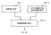
ついで、実画像情報を算出する。実画像情報算出の手順を、図10のフローチャートを参照しながら説明する。
ついで、実画像情報を算出する。実画像情報算出の手順を、図10のフローチャートを参照しながら説明する。
(図10のステップSD-1)
まず、撮像部1により、対象物を含む画像である実画像を取得する。画像の取得方法自体は背景画像の場合と同様である。ただし、対象物を視線が追跡する場合は、1回の実画像取得ごとに以下の差分抽出処理を行うことが望ましい。
まず、撮像部1により、対象物を含む画像である実画像を取得する。画像の取得方法自体は背景画像の場合と同様である。ただし、対象物を視線が追跡する場合は、1回の実画像取得ごとに以下の差分抽出処理を行うことが望ましい。
(図10のステップSD-2)
一方、視線方向取得部21及び視点位置取得部22により、カメラ11の視線方向及び視点位置を取得する。これについても、背景画像の場合と同様でよい。
一方、視線方向取得部21及び視点位置取得部22により、カメラ11の視線方向及び視点位置を取得する。これについても、背景画像の場合と同様でよい。
(図10のステップSD-3)
ついで、座標変換部23により、カメラ11の視線方向及び視点位置の情報を用いて、実画像における画素の位置情報を、固定座標系における極座標情報に変換する。この座標変換処理も、前記した背景画像と同様に行うことができる。得られた極座標情報は、対象背景抽出部4に送られる。
ついで、座標変換部23により、カメラ11の視線方向及び視点位置の情報を用いて、実画像における画素の位置情報を、固定座標系における極座標情報に変換する。この座標変換処理も、前記した背景画像と同様に行うことができる。得られた極座標情報は、対象背景抽出部4に送られる。
(図4のステップSA-3)
次に、対象背景抽出部4は、実画像における画素の極座標情報を用いて、実画像に対応する角度領域での背景画像を対象背景として特定する。さらに具体的には、対象背景抽出部4は、実画像の極座標情報(実際には量子化されている)に基づいて、実画像が撮影した領域に対応する領域での背景画像を特定することができる。したがって、対象背景抽出部4は、実画像に対応する範囲を特定する極座標情報を記録部3に送り、その極座標情報に対応する対象背景の画像(つまり画素情報)を指定あるいは取得することができる。
次に、対象背景抽出部4は、実画像における画素の極座標情報を用いて、実画像に対応する角度領域での背景画像を対象背景として特定する。さらに具体的には、対象背景抽出部4は、実画像の極座標情報(実際には量子化されている)に基づいて、実画像が撮影した領域に対応する領域での背景画像を特定することができる。したがって、対象背景抽出部4は、実画像に対応する範囲を特定する極座標情報を記録部3に送り、その極座標情報に対応する対象背景の画像(つまり画素情報)を指定あるいは取得することができる。
(図4のステップSA-4)
次に、差分抽出部5は、実画像と対象背景とを比較することによって、それらの間の差分を抽出する。実画像と対象背景とは、実空間(図7(a)における平面Πと言ってもよい)における同じ領域の画像となっているので、それらの画素どうしの情報(色情報)を比較することによって、背景差分を抽出することができる。
次に、差分抽出部5は、実画像と対象背景とを比較することによって、それらの間の差分を抽出する。実画像と対象背景とは、実空間(図7(a)における平面Πと言ってもよい)における同じ領域の画像となっているので、それらの画素どうしの情報(色情報)を比較することによって、背景差分を抽出することができる。
ここで、背景差分の抽出においては、画像平面上での画素位置を基準とする方法(つまり画像空間内で行う方法)と、極座標上での画素位置を基準とする方法(つまり極座標空間内で行う方法)とがある。画像平面上での画素位置を基準とする場合は、極座標と画像平面上の画素位置との対応関係(この対応関係は極座標算出時に算出されている)を使って、画素位置を基準として、同一位置の画素どうしを比較することができる。一方、極座標上での画素位置を基準とする場合は、同じ極座標に対応する画素どうしを比較すればよい。なお、前記した通り、本実施形態においては、極座標情報を量子化したので、量子化された極座標ごとの比較が行われる。また、画像空間内で抽出を行う場合も、極座標が量子化されているので、結果的には位置情報が量子化されていることになる。
なお、背景か対象物かを判定する場合、画素単位で比較するよりも、当該画素の周辺の画素情報を加味して判断することが妥当であると考えられる。これは、つぎの理由による:
・照明のフリッカやカメラのノイズによって画素値がある程度変動すると予想されること;
・実際の視線方向のブレ、量子化時の丸め誤差、あるいは各種の機械的誤差のために、全視野背景から抽出した背景画像と実際の背景との間には多少のずれが生じると予想されること。
・照明のフリッカやカメラのノイズによって画素値がある程度変動すると予想されること;
・実際の視線方向のブレ、量子化時の丸め誤差、あるいは各種の機械的誤差のために、全視野背景から抽出した背景画像と実際の背景との間には多少のずれが生じると予想されること。
そのため、例えば極座標を基準として判定する場合、対象の画素位置に対応する極座標(θmn,φn)を中心とする周辺、つまり
(θ(m+k)(n+l),φ(n+l))(ここで|k|,|l|<2~3程度)
に登録された画素値全てについて実画像と背景画像とを比較して、背景か否かを判断するのが妥当と考えられる。画像上の座標を基準とする場合は、これらの極座標に対応する画像座標を算出して、差分抽出を行うことができる。なお、本実施形態においては、前記した背景差分による対象抽出に加えて、画像特徴を利用した対象抽出を行うこともできる。つまり、背景差分による対象抽出と、画像特徴を利用した対象抽出のAND条件により、対象の位置を精度よく特定することが可能である。
(θ(m+k)(n+l),φ(n+l))(ここで|k|,|l|<2~3程度)
に登録された画素値全てについて実画像と背景画像とを比較して、背景か否かを判断するのが妥当と考えられる。画像上の座標を基準とする場合は、これらの極座標に対応する画像座標を算出して、差分抽出を行うことができる。なお、本実施形態においては、前記した背景差分による対象抽出に加えて、画像特徴を利用した対象抽出を行うこともできる。つまり、背景差分による対象抽出と、画像特徴を利用した対象抽出のAND条件により、対象の位置を精度よく特定することが可能である。
(図4のステップSA-5)
ついで、差分抽出部5は、得られた差分情報(つまり対象物の位置情報)を、図示しない制御部に送る。制御部では、カメラ11の視線方向が対象物の位置を向くように、駆動部12を制御する。これにより、対象物をカメラ11で追跡することができる。前記した各処理が十分高速であれば、移動する対象物をカメラ画像のほぼ中心に配置することが可能となる。
ついで、差分抽出部5は、得られた差分情報(つまり対象物の位置情報)を、図示しない制御部に送る。制御部では、カメラ11の視線方向が対象物の位置を向くように、駆動部12を制御する。これにより、対象物をカメラ11で追跡することができる。前記した各処理が十分高速であれば、移動する対象物をカメラ画像のほぼ中心に配置することが可能となる。
(図4のステップSA-6)
差分抽出部5で抽出された差分以外の部分は、背景を表す情報(つまり背景情報)として利用可能である。そこで、本実施形態の差分抽出部5は、背景情報を背景更新部6に送る。背景情報は、背景に相当する部分の位置情報(この例では量子化された極座標情報)と、その位置における画素の色情報とを含む。背景更新部6は、背景情報を用いて、記録部3における背景画素情報を極座標情報により特定して更新することができる。これにより、背景情報を最新のものに更新できるので、背景差分の抽出精度を向上させることができる。なお、背景情報の更新は、背景差分が抽出されるたびに行う必要はなく、所定時間間隔ごとに行うことも可能である。あるいは、背景差分抽出による背景情報の更新処理を省略することもでき、例えば、所定時間ごとに、全背景情報を再取得して更新してもよい。
差分抽出部5で抽出された差分以外の部分は、背景を表す情報(つまり背景情報)として利用可能である。そこで、本実施形態の差分抽出部5は、背景情報を背景更新部6に送る。背景情報は、背景に相当する部分の位置情報(この例では量子化された極座標情報)と、その位置における画素の色情報とを含む。背景更新部6は、背景情報を用いて、記録部3における背景画素情報を極座標情報により特定して更新することができる。これにより、背景情報を最新のものに更新できるので、背景差分の抽出精度を向上させることができる。なお、背景情報の更新は、背景差分が抽出されるたびに行う必要はなく、所定時間間隔ごとに行うことも可能である。あるいは、背景差分抽出による背景情報の更新処理を省略することもでき、例えば、所定時間ごとに、全背景情報を再取得して更新してもよい。
(図4のステップSA-7)
ついで、カメラ11により新しい実画像を取得した場合は、ステップSA-2に戻り、前記した処理を繰り返す。そうでなければ処理を終了する。
ついで、カメラ11により新しい実画像を取得した場合は、ステップSA-2に戻り、前記した処理を繰り返す。そうでなければ処理を終了する。
本実施形態によれば、視点が移動するカメラを用いた場合において、背景差分抽出を高速で、かつ精度よく行うことが可能となる。例えばリアルタイムでの球技の中継放送において、ボール自体を常に追跡する画像を提供することが可能となる。例えば、常にボールを中心においた動画(例えば、卓球において、あたかもボールの背後から常に周囲を見ているかのような動画)のように、新たな付加価値を持つ画像を提供できるという利点がある。また、本実施形態の装置は、医療やファクトリーオートメーションやロボットビジョンなど、各種の分野において応用可能であると考えられる。
(第2実施形態)
次に、本発明の第2実施形態に係る背景差分抽出装置を、主に図11を参照しながら説明する。この第2実施形態の説明においては、前記した第1実施形態の背景差分抽出装置と基本的に共通する構成要素については、同一の符号を付すことにより、説明の煩雑を避ける。
次に、本発明の第2実施形態に係る背景差分抽出装置を、主に図11を参照しながら説明する。この第2実施形態の説明においては、前記した第1実施形態の背景差分抽出装置と基本的に共通する構成要素については、同一の符号を付すことにより、説明の煩雑を避ける。
第2実施形態の装置は、ブラー生成部7を追加的に備えている点で、第1実施形態の装置と相違している。ブラー生成部7は、対象背景を、視線方向が移動する方向に沿って複数枚特定し、特定された複数枚の対象背景を合成することによって、ブラーを有する合成対象背景を生成する処理を行う機能要素である。また、第2実施形態の差分抽出部5は、実画像と合成対象背景とを比較することによって、差分を抽出する構成とされている。さらに、この第2実施形態では、背景更新部6を省略しており、逐次の背景更新は行わないものとされている。したがって、記録部3に記録されている背景画像は、初期に取得された全背景の画像(あるいはその後に再取得された全背景の画像)となっている。
モーションブラー(この明細書においては単に「ブラー」と称する)とは、被写体もしくはカメラ自体が露光中に動くことによって生じる画像のぶれである。追跡対象が常に画像内の固定位置に撮影されるように撮影すると、対象の移動速度によっては、露光時間を短くしても風景部分に大きなぶれ(すなわちブラー)を生じることがある。一方、記録部3に記録されている背景画素情報は、通常、静止状態を前提としているので、背景画像にはブラーは存在しない。したがって、このようなぶれを生じると、背景差分を正確に抽出することが一般的には難しくなるという問題がある。そこで、背景画像にも画像処理によりブラーを生じさせることが考えられる。しかしながら、従来から提案されているブラーカーネルを用いたブラー除去(参考文献:P. Hansen and J. N. D. Oleary: "Deblurring Images: Matrices, Spectra, and Filtering", SIAM Press (2006).)は多くの計算量を要するため、実時間システムへの組み込みには適さない。そこで本実施形態では、カメラ11の視線方向が既知という条件を利用して「ブラーを含んだ背景画像」を合成し、背景差分を行う。
以下、ブラー生成処理の具体例について詳しく説明する。
(ブラー生成処理)
カメラから得られる映像は、露光中に各受像素子に入射する光の総和として得られる。つまり、時刻tからΔt秒間の露光によって得られる画像I(t)は以下の式で表現できる。
カメラから得られる映像は、露光中に各受像素子に入射する光の総和として得られる。つまり、時刻tからΔt秒間の露光によって得られる画像I(t)は以下の式で表現できる。

ここでi(θc,φc)は、視線方向(θc,φc)における静止時の画像を表す。ただし、システムの実装においてはi(θc,φc)は連続的ではなく離散的に取得されるため、露光中のサンプリング回数をnとして、下記I^を推定値として得ることができる。

ここで(θc[k],φc[k])は、k回目のサンプリング時(時刻t+(k/n)Δt)における視線方向を表す。この処理は、「対象背景を、視線方向が移動する方向に沿って複数枚特定し、特定された複数枚の対象背景を合成することによって、ブラーを有する合成対象背景I^を生成する処理」に相当する。以上の説明から明らかなように、露光中の各時刻における視線方向を決定できれば、全視野背景に基づいて、モーションブラーを含んだ背景画像を合成することができる。
背景画像にモーションブラーを生成できれば、差分抽出の精度を向上させることが期待できる。
なお、前記のブラー生成処理において、ブラー生成のために合成する画像枚数は、基本的には、視線の移動速度によって決定することができる。すなわち、画像取得のサンプリング間隔とカメラの露光時間Δtとは通常一定であるが、一定の露光時間Δt内で取得された画像のうち、何枚を用いてブラー生成を行うかを、視線の移動速度によって決めることができる。例えば、視線移動速度が低いときは、Δt内での全取得画像を用いるのではなく、ある程度の画像を間引いて合成することが考えられる。このように、視線移動速度に応じて、ブラー生成に用いる画像枚数を変更することができる。
第2実施形態の装置における他の構成及び利点は、前記した第1実施形態と同様なので、これ以上詳しい説明は省略する。
なお、本発明の内容は、前記各実施形態に限定されるものではない。本発明は、特許請求の範囲に記載された範囲内において、具体的な構成に対して種々の変更を加えうるものである。
例えば、前記した各構成要素は、機能ブロックとして存在していればよく、独立したハードウエアとして存在しなくても良い。また、実装方法としては、ハードウエアを用いてもコンピュータソフトウエアを用いても良い。さらに、本発明における一つの機能要素が複数の機能要素の集合によって実現されても良く、本発明における複数の機能要素が一つの機能要素により実現されても良い。
また、機能要素は、物理的に離間した位置に配置されていてもよい。この場合、機能要素どうしがネットワークにより接続されていても良い。グリッドコンピューティング又はクラウドコンピューティングにより機能を実現し、あるいは機能要素を構成することも可能である。
さらに、前記した実施形態においては、いわゆるサッカードミラーを用いてカメラの視点を動かす例を説明したが、これに限らず、視点が可動なカメラであれば、本発明を適用することが可能であると考えられる。
Claims (10)
- 視線方向及び視点位置が移動可能なカメラで得られた画像を用いて背景差分を抽出するための装置であって、
撮像部と、極座標算出部と、記録部と、対象背景抽出部と、差分抽出部とを備えており、
前記撮像部は、カメラと、駆動部とを備えており、
前記カメラは、対象物を含まない画像である背景画像、あるいは、対象物を含む画像である実画像を取得できる構成となっており、
前記駆動部は、前記カメラの視線方向及び視点位置を変更できる構成となっており、
前記極座標算出部は、視線方向取得部と、視点位置取得部と、座標変換部とを備えており、
前記視線方向取得部は、前記カメラにおける視線方向を取得する構成となっており、
前記視点位置取得部は、前記カメラにおける視点位置を取得する構成となっており、
前記座標変換部は、取得された前記視線方向及び視点位置を用いて、前記背景画像あるいは前記実画像における画素の位置情報を、固定座標系における極座標情報に変換する構成となっており、
前記記録部は、前記背景画像における画素の色情報と、当該画素の極座標情報との対応関係を記録する構成となっており、
前記対象背景抽出部は、前記実画像における画素の極座標情報を用いて、前記実画像に対応する角度領域での前記背景画像を対象背景として特定する構成となっており、
前記差分抽出部は、前記実画像と前記対象背景とを比較することによって、それらの間の差分を抽出する構成となっている
背景差分抽出装置。 - 前記座標変換部における、前記極座標情報への変換は、
前記背景画像あるいは前記実画像における画素の位置情報を、視点が固定された仮想カメラにおける仮想画像上での、当該画素の位置情報である仮想位置情報に変換する処理と、
前記仮想位置情報を、前記固定座標系における極座標情報に変換する処理と
によって行われる構成となっている
請求項1に記載の背景差分抽出装置。 - さらに量子化部を備えており、
前記量子化部は、前記座標変換部で得られた前記極座標情報を量子化する構成とされており、
さらに、前記量子化部は、前記カメラにおける視線方向が前記固定座標系における基準方向からずれるほど、量子化単位としての角度範囲を増やす構成とされており、
前記記録部は、前記画素の極座標情報として、量子化された前記極座標情報を用いる構成とされている
請求項1又は2に記載の背景差分抽出装置。 - さらに、ブラー生成部を備えており、
前記ブラー生成部は、前記対象背景を、前記視線方向が移動する方向に沿って複数枚特定し、特定された複数枚の前記対象背景を合成することによって、ブラーを有する合成対象背景を生成する構成とされており、
前記差分抽出部は、前記実画像と前記合成対象背景とを比較することによって、前記差分を抽出する構成とされている
請求項1~3のいずれか1項に記載の背景差分抽出装置。 - 前記カメラの視線方向は、パン方向角度とチルト方向角度とによってあらわされている
請求項1~4のいずれか1項に記載の背景差分抽出装置。 - 前記駆動部は、前記カメラの視線方向をパン方向とチルト方向とに変化させる鏡面光学系を備えている
請求項1~5のいずれか1項に記載の背景差分抽出装置。 - さらに、背景更新部を備えており、
前記背景更新部は、前記実画像のうち、前記差分抽出部において前記差分とされなかった部分を新たな背景画像として特定して、前記記録部における前記背景画像における画素の色情報を更新する構成とされている
請求項1~6のいずれか1項に記載の背景差分抽出装置。 - 前記駆動部は、前記差分抽出部によって差分として抽出された部分に前記カメラの視線方向を向ける構成とされている
請求項1~7のいずれか1項に記載の背景差分抽出装置。 - 視線方向及び視点位置が移動可能なカメラで得られた画像を用いて背景差分を抽出するための方法であって、
前記カメラにより、対象物を含まない画像である背景画像を取得するステップと、
前記カメラの視線方向及び視点位置の情報を用いて、前記背景画像における画素の位置情報を、前記固定座標系における極座標情報に変換するステップと、
前記背景画像における画素の色情報と、当該画素の極座標情報との対応関係を記録部に記録するステップと、
前記カメラにより、対象物を含む画像である実画像を取得するステップと、
前記カメラの視線方向及び視点位置の情報を用いて、前記実画像における画素の位置情報を、固定座標系における極座標情報に変換するステップと、
前記実画像における画素の極座標情報を用いて、前記実画像に対応する角度領域での前記背景画像を対象背景として特定するステップと、
前記実画像と前記対象背景とを比較することによって、それらの間の差分を抽出するステップと
を備えることを特徴とする背景差分抽出方法。 - 視線方向及び視点位置が移動可能なカメラで得られた画像を用いて背景差分を抽出するためのコンピュータプログラムであって、
対象物を含まない画像である背景画像をカメラに取得させるステップと、
前記カメラの視線方向及び視点位置の情報を用いて、前記背景画像における画素の位置情報を、固定座標系における極座標情報に変換するステップと、
前記背景画像における画素の色情報と、当該画素の極座標情報との対応関係を記録部に記録するステップと、
対象物を含む画像である実画像を前記カメラに取得させるステップと、
前記カメラの視線方向及び視点位置の情報を用いて、前記実画像における画素の位置情報を、前記固定座標系における極座標情報に変換するステップと、
前記実画像における画素の極座標情報を用いて、前記実画像に対応する角度領域での前記背景画像を対象背景として特定するステップと、
前記実画像と前記対象背景とを比較することによって、それらの間の差分を抽出するステップと
をコンピュータに実行させるためのコンピュータプログラム。
Priority Applications (2)
| Application Number | Priority Date | Filing Date | Title |
|---|---|---|---|
| US14/890,150 US9924104B2 (en) | 2013-05-09 | 2014-04-28 | Background-differential extraction device and background-differential extraction method |
| CN201480025487.7A CN105210368B (zh) | 2013-05-09 | 2014-04-28 | 背景差分提取装置以及背景差分提取方法 |
Applications Claiming Priority (2)
| Application Number | Priority Date | Filing Date | Title |
|---|---|---|---|
| JP2013099408A JP6090786B2 (ja) | 2013-05-09 | 2013-05-09 | 背景差分抽出装置及び背景差分抽出方法 |
| JP2013-099408 | 2013-05-09 |
Publications (1)
| Publication Number | Publication Date |
|---|---|
| WO2014181726A1 true WO2014181726A1 (ja) | 2014-11-13 |
Family
ID=51867207
Family Applications (1)
| Application Number | Title | Priority Date | Filing Date |
|---|---|---|---|
| PCT/JP2014/061826 Ceased WO2014181726A1 (ja) | 2013-05-09 | 2014-04-28 | 背景差分抽出装置及び背景差分抽出方法 |
Country Status (4)
| Country | Link |
|---|---|
| US (1) | US9924104B2 (ja) |
| JP (1) | JP6090786B2 (ja) |
| CN (1) | CN105210368B (ja) |
| WO (1) | WO2014181726A1 (ja) |
Cited By (3)
| Publication number | Priority date | Publication date | Assignee | Title |
|---|---|---|---|---|
| US9924104B2 (en) | 2013-05-09 | 2018-03-20 | The University Of Tokyo | Background-differential extraction device and background-differential extraction method |
| JP2018088065A (ja) * | 2016-11-28 | 2018-06-07 | 株式会社Nttファシリティーズ | 情報可視化システム、情報可視化方法、及びプログラム |
| CN114519684A (zh) * | 2021-11-29 | 2022-05-20 | 盛视科技股份有限公司 | 一种基于图像差分的引体向上计数方法 |
Families Citing this family (15)
| Publication number | Priority date | Publication date | Assignee | Title |
|---|---|---|---|---|
| US10802620B2 (en) * | 2015-03-17 | 2020-10-13 | Sony Corporation | Information processing apparatus and information processing method |
| JPWO2017073045A1 (ja) * | 2015-10-28 | 2018-08-02 | 京セラ株式会社 | 撮像装置、撮像システム、対象者監視システム、および撮像装置の制御方法 |
| JP6489649B2 (ja) * | 2015-11-16 | 2019-03-27 | 株式会社 日立産業制御ソリューションズ | モーションブラー補償装置、撮像システム、および、モーションブラー補償方法 |
| CN106570832A (zh) * | 2016-10-31 | 2017-04-19 | 北京尚水信息技术股份有限公司 | 一种基于最小值背景差分的piv图像处理方法 |
| CN108540782B (zh) * | 2017-03-03 | 2020-09-22 | 株式会社理光 | 获取差分图像的方法和装置 |
| KR102549503B1 (ko) * | 2017-12-20 | 2023-06-30 | 삼성전자주식회사 | 저전력 상태에서 이미지들의 출력 타이밍을 동기화하기 위한 디스플레이 구동 회로 |
| CN108171706B (zh) * | 2018-01-22 | 2021-08-17 | 井冈山大学 | 一种计算机图像处理方法 |
| JP2019152980A (ja) * | 2018-03-01 | 2019-09-12 | キヤノン株式会社 | 画像処理装置、画像処理方法、及びプログラム |
| JP6452875B1 (ja) * | 2018-03-29 | 2019-01-16 | 株式会社日立製作所 | 移動体撮像システム、及び、移動体撮像方法 |
| US12444070B2 (en) | 2020-02-28 | 2025-10-14 | Nec Corporation | Measuring method, measuring apparatus, and measuring system |
| KR102558294B1 (ko) * | 2020-12-31 | 2023-07-24 | 한국과학기술연구원 | 임의 시점 영상 생성 기술을 이용한 다이나믹 영상 촬영 장치 및 방법 |
| CN113110542B (zh) * | 2021-04-16 | 2022-07-15 | 东北大学 | 一种基于单轴云台的四旋翼无人机目标追踪系统 |
| CN113296546B (zh) * | 2021-04-22 | 2023-01-06 | 杭州晟冠科技有限公司 | 一种轮船联动跟踪定位误差的补偿方法 |
| CN113627323B (zh) * | 2021-08-09 | 2024-05-07 | 上海擎朗智能科技有限公司 | 一种图像处理方法、机器人及介质 |
| JP2023122677A (ja) * | 2022-02-24 | 2023-09-05 | 東レエンジニアリング株式会社 | ウエーハ検査装置 |
Citations (3)
| Publication number | Priority date | Publication date | Assignee | Title |
|---|---|---|---|---|
| JPH1021407A (ja) * | 1996-06-28 | 1998-01-23 | Osaka Kagaku Gijutsu Center | 動き検出装置 |
| JP2009236569A (ja) * | 2008-03-26 | 2009-10-15 | Zynas Corp | 接地点推定装置、接地点推定方法、動線表示システムおよびサーバ |
| JP2010244207A (ja) * | 2009-04-02 | 2010-10-28 | Univ Of Tokyo | 移動物体追跡装置、移動物体追跡方法および移動物体追跡プログラム |
Family Cites Families (9)
| Publication number | Priority date | Publication date | Assignee | Title |
|---|---|---|---|---|
| JP2003141562A (ja) * | 2001-10-29 | 2003-05-16 | Sony Corp | 非平面画像の画像処理装置及び画像処理方法、記憶媒体、並びにコンピュータ・プログラム |
| US9094615B2 (en) * | 2004-04-16 | 2015-07-28 | Intheplay, Inc. | Automatic event videoing, tracking and content generation |
| TWI353778B (en) * | 2007-12-21 | 2011-12-01 | Ind Tech Res Inst | Moving object detection apparatus and method |
| CN100583126C (zh) | 2008-01-14 | 2010-01-20 | 浙江大学 | 基于快速图像配准的视角变化条件下视频前景提取方法 |
| US8405720B2 (en) * | 2008-08-08 | 2013-03-26 | Objectvideo, Inc. | Automatic calibration of PTZ camera system |
| CN102034240A (zh) * | 2010-12-23 | 2011-04-27 | 北京邮电大学 | 一种静态前景检测和跟踪方法 |
| CN102025981B (zh) * | 2010-12-23 | 2013-12-04 | 北京邮电大学 | 一种监控视频中的前景检测的方法 |
| CN103077520B (zh) * | 2013-01-04 | 2016-02-24 | 浙江大学 | 一种针对移动摄像机的背景减除方法 |
| JP6090786B2 (ja) | 2013-05-09 | 2017-03-08 | 国立大学法人 東京大学 | 背景差分抽出装置及び背景差分抽出方法 |
-
2013
- 2013-05-09 JP JP2013099408A patent/JP6090786B2/ja active Active
-
2014
- 2014-04-28 CN CN201480025487.7A patent/CN105210368B/zh not_active Expired - Fee Related
- 2014-04-28 US US14/890,150 patent/US9924104B2/en active Active
- 2014-04-28 WO PCT/JP2014/061826 patent/WO2014181726A1/ja not_active Ceased
Patent Citations (3)
| Publication number | Priority date | Publication date | Assignee | Title |
|---|---|---|---|---|
| JPH1021407A (ja) * | 1996-06-28 | 1998-01-23 | Osaka Kagaku Gijutsu Center | 動き検出装置 |
| JP2009236569A (ja) * | 2008-03-26 | 2009-10-15 | Zynas Corp | 接地点推定装置、接地点推定方法、動線表示システムおよびサーバ |
| JP2010244207A (ja) * | 2009-04-02 | 2010-10-28 | Univ Of Tokyo | 移動物体追跡装置、移動物体追跡方法および移動物体追跡プログラム |
Non-Patent Citations (1)
| Title |
|---|
| KEIKO YOKOYAMA ET AL.: "Kosoku Shisen Seigyo System o Mochiita Buttai Tsuiseki no Tameno Haikei Jokyo Algorithm", THE 13TH SICE SYSTEM INTEGRATION DIVISION ANNUAL CONFERENCE ( SI 2012), KOEN RONBUNSHU, THE SOCIETY OF INSTRUMENT AND CONTROL ENGINEERS, 18 December 2012 (2012-12-18), pages 2237 - 2240 * |
Cited By (3)
| Publication number | Priority date | Publication date | Assignee | Title |
|---|---|---|---|---|
| US9924104B2 (en) | 2013-05-09 | 2018-03-20 | The University Of Tokyo | Background-differential extraction device and background-differential extraction method |
| JP2018088065A (ja) * | 2016-11-28 | 2018-06-07 | 株式会社Nttファシリティーズ | 情報可視化システム、情報可視化方法、及びプログラム |
| CN114519684A (zh) * | 2021-11-29 | 2022-05-20 | 盛视科技股份有限公司 | 一种基于图像差分的引体向上计数方法 |
Also Published As
| Publication number | Publication date |
|---|---|
| US20160088231A1 (en) | 2016-03-24 |
| CN105210368A (zh) | 2015-12-30 |
| JP6090786B2 (ja) | 2017-03-08 |
| JP2014219874A (ja) | 2014-11-20 |
| CN105210368B (zh) | 2018-10-26 |
| US9924104B2 (en) | 2018-03-20 |
Similar Documents
| Publication | Publication Date | Title |
|---|---|---|
| JP6090786B2 (ja) | 背景差分抽出装置及び背景差分抽出方法 | |
| CN111147741B (zh) | 基于对焦处理的防抖方法和装置、电子设备、存储介质 | |
| JP6768156B2 (ja) | 仮想的に拡張された視覚的同時位置特定及びマッピングのシステム及び方法 | |
| EP4071713B1 (en) | Parameter calibration method and apapratus | |
| CN108363946B (zh) | 基于无人机的人脸跟踪系统及方法 | |
| US8848035B2 (en) | Device for generating three dimensional surface models of moving objects | |
| JP2020506487A (ja) | シーンから深度情報を取得するための装置および方法 | |
| WO2017020150A1 (zh) | 一种图像处理方法、装置及摄像机 | |
| CN101140661A (zh) | 一种以动态投影为背景的实时目标识别方法 | |
| JP2012222743A (ja) | 撮像装置 | |
| CN110544273B (zh) | 运动捕捉方法、装置以及系统 | |
| KR20200103374A (ko) | 2차원 이미지를 이용한 3차원 모델링 방법 | |
| CN112640419A (zh) | 跟随方法、可移动平台、设备和存储介质 | |
| CN111712857A (zh) | 图像处理方法、装置、云台和存储介质 | |
| CN110544278B (zh) | 刚体运动捕捉方法及装置、agv位姿捕捉系统 | |
| CN114241127A (zh) | 全景图像生成方法、装置、电子设备和介质 | |
| US20250076974A1 (en) | Gaze-adaptive image reprojection | |
| CN110060295B (zh) | 目标定位方法及装置、控制装置、跟随设备及存储介质 | |
| WO2021149509A1 (ja) | 撮像装置、撮像方法、及び、プログラム | |
| CN115278049B (zh) | 拍摄方法及其装置 | |
| US12205328B2 (en) | System for tracking camera and control method thereof | |
| CN112308972A (zh) | 一种大规模电缆隧道环境模型重构方法 | |
| JP7164873B2 (ja) | 画像処理装置及びプログラム | |
| CN116634256B (zh) | 前置楔形棱镜的事件相机 | |
| Zhang et al. | FoveaCam++: Systems-Level Advances for Long Range Multi-Object High-Resolution Tracking |
Legal Events
| Date | Code | Title | Description |
|---|---|---|---|
| 121 | Ep: the epo has been informed by wipo that ep was designated in this application |
Ref document number: 14794401 Country of ref document: EP Kind code of ref document: A1 |
|
| NENP | Non-entry into the national phase |
Ref country code: DE |
|
| WWE | Wipo information: entry into national phase |
Ref document number: 14890150 Country of ref document: US |
|
| 122 | Ep: pct application non-entry in european phase |
Ref document number: 14794401 Country of ref document: EP Kind code of ref document: A1 |