WO2014181802A1 - 据置型の情報コード読取装置 - Google Patents
据置型の情報コード読取装置 Download PDFInfo
- Publication number
- WO2014181802A1 WO2014181802A1 PCT/JP2014/062267 JP2014062267W WO2014181802A1 WO 2014181802 A1 WO2014181802 A1 WO 2014181802A1 JP 2014062267 W JP2014062267 W JP 2014062267W WO 2014181802 A1 WO2014181802 A1 WO 2014181802A1
- Authority
- WO
- WIPO (PCT)
- Prior art keywords
- visual field
- field range
- reading
- information code
- wall portion
- Prior art date
- Legal status (The legal status is an assumption and is not a legal conclusion. Google has not performed a legal analysis and makes no representation as to the accuracy of the status listed.)
- Ceased
Links
Images



Classifications
-
- G—PHYSICS
- G06—COMPUTING OR CALCULATING; COUNTING
- G06K—GRAPHICAL DATA READING; PRESENTATION OF DATA; RECORD CARRIERS; HANDLING RECORD CARRIERS
- G06K7/00—Methods or arrangements for sensing record carriers, e.g. for reading patterns
- G06K7/10—Methods or arrangements for sensing record carriers, e.g. for reading patterns by electromagnetic radiation, e.g. optical sensing; by corpuscular radiation
- G06K7/10544—Methods or arrangements for sensing record carriers, e.g. for reading patterns by electromagnetic radiation, e.g. optical sensing; by corpuscular radiation by scanning of the records by radiation in the optical part of the electromagnetic spectrum
- G06K7/10712—Fixed beam scanning
- G06K7/10722—Photodetector array or CCD scanning
-
- G—PHYSICS
- G06—COMPUTING OR CALCULATING; COUNTING
- G06K—GRAPHICAL DATA READING; PRESENTATION OF DATA; RECORD CARRIERS; HANDLING RECORD CARRIERS
- G06K7/00—Methods or arrangements for sensing record carriers, e.g. for reading patterns
- G06K7/10—Methods or arrangements for sensing record carriers, e.g. for reading patterns by electromagnetic radiation, e.g. optical sensing; by corpuscular radiation
- G06K7/10544—Methods or arrangements for sensing record carriers, e.g. for reading patterns by electromagnetic radiation, e.g. optical sensing; by corpuscular radiation by scanning of the records by radiation in the optical part of the electromagnetic spectrum
- G06K7/10821—Methods or arrangements for sensing record carriers, e.g. for reading patterns by electromagnetic radiation, e.g. optical sensing; by corpuscular radiation by scanning of the records by radiation in the optical part of the electromagnetic spectrum further details of bar or optical code scanning devices
- G06K7/10831—Arrangement of optical elements, e.g. lenses, mirrors, prisms
Definitions
- the present invention relates to a reading device that reads an information code, and more particularly to a stationary information code reading device.
- a stationary information code reader generally includes a case in which a reading port is formed, and various components such as an imaging unit are accommodated in the case. This case (that is, the apparatus main body) is used by being placed on the placement surface. In use, the information code is imaged through the reading port, and the information code is decoded by a known decoding method based on the captured image.
- the user touches the reading object with respect to the reading device placed on the placement surface, and is attached to the reading object.
- a general method is to make the reader recognize the information code. In other words, it is common not to bring the reading device closer to the reading object as in the portable type, but to read the reading object closer to the reading device, so the user does not care much about the alignment. It is desirable that both be read well.
- the user brings the reading object into contact with the reading port, in the reading apparatus, even when the reading object is close to or in contact with the reading port, the entire information code attached thereto Must be imaged well.
- a reflection part that reflects light entering from the reading port is provided, and reflected light from the information code is reflected by the reflection part and reflected by the reflection part.
- a configuration in which light is imaged on a light receiving sensor by an imaging lens is also assumed.
- the path of the visual field range that extends from the imaging unit to the outside of the case is set to be bent in the case. That is, even if the thickness of the case is not so large, it is easy to ensure a large distance from the optical system to the reading port (distance of the path in the visual field range), and thus it is easy to reduce the thickness of the case.
- the distance from the optical system to the reading port (the distance of the path of the visual field range) is ensured using the reflective portion in this way, the visual field range that is bent by the reflective portion (the visual field range that continues from the reflective portion to the outside of the case)
- the visual field range that is bent by the reflective portion (the visual field range that continues from the reflective portion to the outside of the case)
- a part of the image forming part enters the. If a part of the image forming unit enters the field of view in this way, a part of the image forming unit that has entered the image is picked up by the image pickup unit, and that part cannot be used as an image code image pickup region. .
- the present invention has been made to solve the above-described problems, and can be used to reduce the thickness of the entire apparatus, and can easily secure a wide area where an information code can be imaged in the vicinity of the reading port.
- An object is to provide a code reader.
- An imaging unit configured to guide reflected light to the light receiving region, and to form an image of the information code on the light receiving region when the information code is arranged in the field of view.
- a first visual field range located between the imaging unit and the reflective unit, and following the first visual field range and from the reflective unit toward the reading port
- a second visual field range is defined, and the lower end of the reflection region of the reflection unit is positioned at least at the lower end of the first visual field range, and the imaging unit is located outside the second visual field range. Is arranged.
- the reflection unit that reflects light entering from the outside of the case through the reading port is provided, and the imaging unit is provided to guide the light reflected by the reflection unit to the light receiving region.
- the 1st visual field range comprised between the said image formation part and a reflection part, and the 1st constituted from the reflection part to the upper side so that the said 1st visual field range may be followed
- Two viewing fields are defined.
- the reflection part is interposed in the case, and the path of the visual field range extending from the imaging part to the outside of the case (that is, the path for guiding the light entering from the reading port to the imaging part) is bent in the case.
- the case thickness can be reduced by reducing the thickness of the case.
- the lower end of the reflection area of the reflection portion is positioned at least at the lower end of the first visual field range. For this reason, it is possible to prevent a portion outside the reflection region from being reflected on the lower end side of the first visual field range, and it is possible to efficiently arrange the reflection portion appropriately close to the imaging portion.
- the imaging unit is outside the second visual field range that is folded back from the first visual field range. For this reason, a part of the imaging unit is not reflected in the imaging unit, and the reduction of the visual field range caused by the reflection of the imaging unit can be prevented.
- the reflection area of the reflection portion continues from the lower end to the upper end of the first visual field range.
- the reflective area is arranged so as to cover the lower end to the upper end of the first visual field range, it is possible to prevent the upper and lower sides of the reflective area from being reflected, and the visual field resulting from such a reflection. The reduction of the range can be suppressed more reliably.
- a bottom wall portion provided on a placement surface side on which the stationary information code reader is placed and a reading side wall portion in which the reading port is formed are provided to face each other. desirable. And when the opposing direction of the said bottom wall part and the said reading side wall part is made into the up-down direction, it is desirable for the optical axis used as the center of the said 2nd visual field range to be the said up-down direction. If the optical axis of the second visual field range is aligned in the vertical direction in this way, when the user turns the information code horizontally, it becomes easier to capture the information code by suppressing the inclination of the information code, and it is difficult to capture the distorted code image. Become.
- a bottom wall portion provided on a placement surface side on which the stationary information code reader is placed and a reading side wall portion in which the reading port is formed are provided to face each other. desirable.
- the opposing direction of the bottom wall portion and the reading side wall portion is the vertical direction
- the lower end portion of the imaging portion and the lower end portion of the reflecting portion are substantially in the same position in the vertical direction. Is desirable. According to this configuration, since one of the image forming unit and the reflecting unit does not protrude too much below the other, it is easy to efficiently arrange the image forming unit and the reflecting unit at a position closer to the lower side in the case.
- both boundaries of the second visual field range are It is desirable to have a configuration that passes through the inner periphery. With this configuration, the reading port does not go too far into the visual field range, and a wider visual field range can be secured. In particular, in the vicinity of the reading port, if the information code is arranged so as to be within the reading port, the information code is surely within the visual field range, and it becomes easy to reliably image the entire information code.
- a bottom wall portion provided on the placement surface side on which the stationary information code reader is placed in the case and a reading side wall portion in which the reading port is formed are provided to face each other, and the bottom wall
- the optical axis that is the center of the first viewing range is inclined with respect to the horizontal direction It may be set downward.
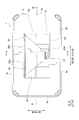
- FIG. 1 is a plan view schematically showing a stationary information code reader according to the first embodiment.
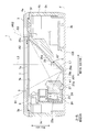
- 2 is a schematic cross-sectional view schematically showing an AA cross section of the stationary information code reader of FIG. 3 is a schematic cross-sectional view schematically showing a BB cross section of the stationary information code reading device of FIG.
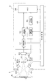
- FIG. 4 is a block diagram schematically illustrating an electrical configuration of the stationary information code reader of FIG.
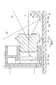
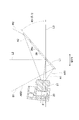
- FIG. 5 is an enlarged cross-sectional view showing a partially enlarged cross section of FIG.
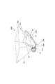
- FIG. 6 is a perspective view for three-dimensionally explaining the reflecting surface of the reflecting portion, the first visual field range, and the boundary (edge) of the second visual field range.
- FIG. 1 is a plan view schematically showing a stationary information code reader according to the first embodiment.
- 2 is a schematic cross-sectional view schematically showing an AA cross section of the stationary information code reader of FIG.
- 3 is a schematic cross-sectional view schematically showing a BB cross section of the stationary information
- FIG. 7 is an enlarged cross-sectional view showing a partially enlarged cross section of FIG.
- FIG. 8 is a schematic cross-sectional view showing Modification 1 of the first embodiment.
- FIG. 9 is a schematic cross-sectional view showing a second modification of the first embodiment.
- a stationary information code reading device 1 (hereinafter also simply referred to as a reading device 1) shown in FIG. 1 is configured as a stationary device that is placed on this placement surface with the upper surface of a desk or shelf as a placement surface. It has a function as an information code reader for reading an information code such as a one-dimensional code such as a barcode or a two-dimensional code such as a QR code (registered trademark).
- the reading device 1 includes a case 3 made of a resin material such as ABS resin.
- the case 3 includes an upper case 4a and a lower case 4b, and is configured as a box as a whole.
- the box-shaped case 3 has a substantially rectangular shape having a longitudinal direction and a short direction.
- the longitudinal direction is referred to as the width direction (or the left-right direction)
- the short direction is referred to as the front-rear direction.
- the case 3 is a stationary type
- the height direction orthogonal to the width direction and the front-rear direction is referred to as the up-down direction (see FIGS. 1 and 2).
- the case 3 accommodates various components such as a reflection section 29, an imaging section 27, and an imaging section 23, which will be described later.
- the upper surface portion (reading side wall portion 3a) of the case 3 has a rectangular shape (a plan view as shown in FIG. 1) with a configuration that penetrates the reading side wall portion 3a in the thickness direction (vertical direction). (Rectangular) reading port 5 is formed.
- the optical system configured by the reflection unit 29, the imaging unit 27, and the imaging unit 23 functions to image an information code outside the case through the reading port 5.
- the case 3 configured in a box shape has a bottom wall portion 3b provided on the placement surface side (placement surface F side) when the stationary information code reader 1 is placed, and a reading port 5.
- the formed reading side wall 3a is provided to face the reading side wall 3a.
- the bottom wall portion 3b is disposed so as to be supported by the mounting surface F, and the reading side wall portion 3a facing the bottom wall portion 3b is configured as an exposed wall portion on the side where the information code C is held. .
- the facing direction of the bottom wall portion 3b and the reading side wall portion 3a coincides with the vertical direction.
- the side where the reading port 5 is formed (the side of the reading side wall 3a) is the upper side, and the opposite side (the side of the bottom wall 3b) is the lower side.
- the direction of the plane perpendicular to the vertical direction is also the horizontal direction.
- a plate 7 is arranged on the upper surface side of the case 3 so as to close the reading port 5.
- the plate 7 is configured as a flat plate having a predetermined thickness, and is configured by a light-transmitting member (for example, transparent acrylic resin or transparent glass) that can transmit light from the outside of the case 3. Yes.
- the plate 7 functions as a dust-proof plate and is arranged in a configuration covering almost the entire opening area of the reading port 5 when viewed in plan as shown in FIG. 1 and closes the reading port 5. Since the plate 7 closes the reading port 5 in this way, foreign matter (dust, dust, etc.) from outside the case is difficult to enter the case 3.
- the reading apparatus 1 mainly includes an optical system such as an illumination light source 21, an imaging unit 27, and an imaging unit 33, and a microcomputer such as a memory 35 and a control circuit 40 (hereinafter referred to as “microcomputer”). And a power supply system such as a power supply unit and a power switch (not shown).
- an optical system such as an illumination light source 21, an imaging unit 27, and an imaging unit 33
- a microcomputer such as a memory 35 and a control circuit 40 (hereinafter referred to as “microcomputer”).
- a power supply system such as a power supply unit and a power switch (not shown).
- the optical system is divided into a light projecting optical system and a light receiving optical system.
- the illumination light source 21 constituting the light projecting optical system functions as a light source capable of irradiating illumination lights C1 and C2, and is composed of, for example, a red LED.
- a plurality of illumination light sources 21 are provided around the plate 7, and FIGS. 3 and 4 show an example in which two illumination light sources 21a and 21b are provided on the left and right.
- FIG. 4 conceptually shows a state in which the illumination lights C1 and C2 are irradiated toward the reading object R on which the information code C is displayed by the two illumination light sources 21a and 21b.
- the light receiving optical system includes an imaging unit 23, an imaging unit 27, a reflection unit 29 (FIG. 1, FIG. 2, etc.), and the like.
- the imaging unit 23 is configured by a light receiving sensor (area sensor) in which solid-state imaging devices such as a CCD element and a CMOS element are two-dimensionally arranged, and receives light from outside the case on the imaging unit 27 side. A possible light receiving surface 23a is arranged.
- the imaging unit 23 is configured to be able to receive the reflected light Lr (see FIG. 4) that is irradiated and reflected on the information code C or the reading object R.
- the imaging unit 23 is mounted on the substrate 24 so that the light reflected by the reflecting unit 29 can receive incident light that passes through the imaging unit 27 and enters the light receiving surface 23a.
- a region where light can be detected on the light receiving surface 23a (a region where the solid-state imaging device is disposed) is set as a “predetermined light receiving region”.
- the range of the area is conceptually indicated by reference numeral D1. That is, the light incident on the range D1 on the light receiving surface 23a is detected by the imaging unit 23.
- the range of the light receiving area in the imaging unit 23 is, for example, a predetermined range in the vertical direction centered on the optical axis L1 on the light receiving surface 23a, and a predetermined range in the horizontal direction (width direction) centered on the optical axis L1. ing.
- the light receiving surface 23a is disposed substantially orthogonal to the front-rear direction.
- the imaging unit 27 is configured by a known imaging lens and functions as an imaging optical system.
- the incident light incident from the outside via the plate 7 (specifically, the incident light is reflected by the reflection unit 29).
- the reflected light is condensed and functions to form an image on the light receiving surface 23a of the imaging unit 23.
- the information code C can be imaged while illuminating light C1 and C2 emitted from the illumination light source 21 against the information code C.
- the reflected light Lr from the information code C is collected, and an image of the information code C is formed on the light receiving surface 23a of the imaging unit 23.
- a wide-angle lens having a short focal length and a wide angle of view can be suitably used.
- the microcomputer system includes an amplification circuit 31, an A / D conversion circuit 34, a memory 35, an address generation circuit 36, a synchronization signal generation circuit 38, a control circuit 40, and the like.
- information captured by the optical system described above The image signal of the code C is configured to be processed.
- the image data when the information code C is imaged by the imaging unit 23 can be stored in the memory 35, and the control circuit 40 analyzes the image data of the information code C, The data recorded in the information code C is decrypted by a known decryption method.
- various electric circuit components including the above-described control circuit 40 are mounted inside the reader 1 at, for example, a portion indicated by reference numeral CB in FIG.
- the reading apparatus 1 may be provided with an operation unit such as a push button. In this configuration, when the user operates the operation unit, the operation unit responds to the operation. The signal is input to the control circuit. Also, a known communication interface may be provided. With this configuration, information can be transmitted from the reading device 1 to an external device (not shown), and the reading device 1 can receive information from the external device. Become. Further, a display unit such as a lamp or a display device may be provided.
- the information code C to be read includes, for example, a QR code (registered trademark), and may be another two-dimensional code such as a data matrix code or a maxi code as long as it is a known code. Alternatively, a known one-dimensional code such as a barcode may be used.
- the method for forming the information code C to be read is not particularly limited, and various methods such as printing, direct marking, and image display are assumed. Also, the materials and applications of reading objects are various, and various materials such as metal materials, resin materials, and papers are targeted, and even mobile terminals (portable information processing devices such as mobile phones and smartphones) can be used. Good.
- the reflection unit 29, the imaging unit 27, and the imaging unit 23 are accommodated in the case 3.
- An illumination light source 21 is provided in a region outside the plate 7.
- the case 3, the reflection unit 29, the imaging unit 27, the imaging unit 23, and the illumination light source 21 will be described in more detail.
- a plate-like reading side wall 3a is provided as an upper surface (upper wall) of the case 3.
- the reading side wall portion 3a constitutes substantially the entire upper case 4a configured in a plate shape, and is configured in a certain thickness range as a whole.
- the reading opening 5 having a rectangular shape in plan view is formed in a rectangular shape as a through-hole in a configuration that penetrates the central portion in the longitudinal direction and the central portion in the short direction of the reading side wall portion 3a when viewed in plan. ing.
- the reading port 5 is formed in such a size and position that the reflection area (reflection area) of the reflection section 29 can be entirely accommodated in the opening area when viewed in plan as shown in FIG. That is, in the width direction, the width direction one end part and the other end part of the reflection part 29 are arranged between the width direction one end part 5a and the width direction other end part 5b. The one end part and the other end part of the reflection part 29 are arranged between the one end part 5c in the front-rear direction and the other end part 5d in the front-rear direction.
- edge part of the width direction one end part 5a and the width direction other end part 5b of the reading opening 5 has extended linearly in the front-back direction, and the front-rear direction one end part 5c and the other end part in the front-rear direction of the reading opening 5 5d extends linearly in the width direction (left-right direction).
- the bottom wall portion 3 b of the case 3 is configured in a plate shape as the lower surface portion of the case 3, and when the reading device 1 is placed on the placement surface F, the bottom wall portion 3 b is formed.
- the lower surface side of the portion 3b is supported by the placement surface F.
- the bottom wall portion 3b has a configuration in which the thickness direction is the vertical direction, and the outer surface (lower surface) is configured as a substantially flat surface. And it functions as the bottom of case 3 comprised in box shape.
- the accommodation space in the case 3 (the space in which the reflection part 29, the imaging part 27, the imaging part 23, etc. are accommodated).
- a side wall portion 3c is provided so as to surround the periphery.
- This side wall part 3c is provided with a pair of side wall arrange
- the reading side wall portion 3a (upper surface portion) is arranged so as to partially close the upper side of the annularly arranged side wall portion 3c (peripheral wall portion), and the bottom is constituted so as to close the entire lower side of the side wall portion 3c.
- Wall part 3b lower surface part is arranged.
- a light-transmitting plate 7 that closes the reading port 5 is arranged in a configuration that is assembled to the case 3 configured as described above.
- a recess 6 is formed between the reading side wall 3 a and the bottom wall 3 b at a position below the reading port 5.
- the opening formed in the upper end portion of the recess 6 is the same size as the opening of the reading port 5 or slightly larger than the opening of the reading port 5, and is configured to be recessed downward on the lower side of the reading port 5.
- 6 is formed in a box shape.
- the reflecting portion 29 and the image forming portion 27 are arranged so as to be assembled inside the concave portion 6.
- the plate 7 is disposed in contact with the upper portion of the recess 6 so as to close the opening at the upper end of the recess 6. That is, the plate 7 is arranged so as to cover the upper side of the reflecting portion 29 and the image forming portion 27 accommodated in the concave portion 6, and when viewed in plan as shown in FIG. The reflection part 29 and the imaging part 27 are visually recognized. As shown in FIGS. 2 and 3, the plate 7 is disposed so as to close the reading port 5 formed in the reading side wall portion 3a from below. In this configuration, the plate 7 closes the lower side of the reading port 5 and closes the reading port 5, but as shown in FIG. There is a gap, and the entire circumference of the reading port 5 is not completely in close contact with the plate 7.
- the plate 7 is interposed between the reading port 5 formed in the upper surface portion of the case 3 and the opening portion of the concave portion 6 formed in the case 3.
- the plate 7 blocks communication between the region and the opening region of the recess 6.
- the plate 7 is configured as a transparent and flat plate material, and is arranged substantially horizontally so that the direction perpendicular to the plate surfaces (the upper surface 7a and the lower surface 7b) is the vertical direction. .
- the reflection unit 29 is configured as a mirror, for example, and is accommodated in the case 3 and functions to reflect light entering from the outside of the case 3 through the reading port 5.
- the reflecting portion 29 is arranged such that the reflecting surface 29a is obliquely upward and faces one side in the front-rear direction, and reflects light that has entered through the reading port 5 from the upper side of the case 3 to one side in the front-rear direction. It is configured. More specifically, the reflection surface 29a is configured to be flat, and the reflection surface 29a is arranged so as to be orthogonal to a virtual plane parallel to the vertical direction and the front-rear direction. For example, light that enters parallel to the vertical direction Are arranged to reflect horizontally.
- the upper end portion 29c of the reflecting portion 29 is disposed at a position close to the plate 7 in the vertical direction (a position close to the opening at the upper end of the recessed portion 6), and the lower end portion 29d of the reflecting portion 29 is located on the bottom wall portion 3b. Located close to the top surface.
- the reflection part 29 becomes a structure which becomes wide as it becomes upper so that the width
- region) of the reflective surface 29a becomes a structure which becomes wide as it becomes upper.
- the imaging unit 27 is configured by an imaging lens that functions as a wide-angle lens as described above, and is disposed at a position away from the plate 7 as shown in FIGS.
- the imaging unit 27 determines a field of view range that can be imaged by the imaging unit 23 inside and outside the case 3, and when the information code C is arranged in the field of view range set outside the case 3, the information code C This function functions to form an image on the light receiving area of the imaging unit 23.
- the image forming unit 27 is configured to guide the light that has entered from the outside of the case 3 through the reading port 5 and reflected by the reflecting unit 29 to the light receiving region of the imaging unit 23, as shown in FIG.
- a first visual field range AR1 configured between the imaging unit 27 and the reflective unit 29 as a visual field range, and a second configured on the upper side from the reflective unit 29 so as to follow the first visual field range AR1.
- a visual field range AR2 is defined. That is, the light from the visual field range is condensed toward the light receiving region of the imaging unit 23 so that the first visual field range AR1 and the second visual field range AR2 are used as the imaging area.
- the first visual field range AR1 is a visual field range that is condensed by the imaging unit 27 and directly captured by the imaging unit 23, and the second visual field range AR2 is an image captured by the reflecting unit 29. It is a field of view range to be imaged.
- the first visual field range AR ⁇ b> 1 is a three-dimensional visual field range that is imaged by the imaging unit 23 in the space between the imaging unit 27 and the reflection unit 29.
- the opening at the tip is set so as to gradually widen as it approaches the reflecting portion 29.
- the optical axis L1 that is the center of the first visual field range AR1 is in the horizontal direction (specifically, the front-rear direction), and the angle formed with the reflection surface 29a is 45 ° (see FIG. 2). ).
- the reading device 1 is cut with a plane passing through the optical axis L1 and parallel to the vertical direction as a cut surface, the first field-of-view range AR1 is expanded most vertically on the cut surface. Yes.
- the lower limit boundary (edge) A1 of the first visual field range AR1 becomes a lower position (lower position) as it approaches the reflecting portion 29.
- the upper limit boundary (edge) A2 of the first visual field range AR1 is configured to become a higher position (upper position) as it approaches the reflecting portion 29.
- the position at which the lower boundary A1 of AR1 reaches the reflecting surface 29a of the reflecting portion 29 (the position where the boundary A1 and the reflecting surface 29a intersect) is the lower end position of the first visual field range AR1. Further, the position at which the upper limit boundary A2 of the first visual field range AR1 reaches the reflection surface 29a of the reflection section 29 (the position where the boundary A2 and the reflection surface 29a intersect) is the upper end position of the first visual field range AR1.
- the lower end of the reflection area of the reflection section 29 (area of the reflection surface 29 a) is positioned at least at the lower end of the first visual field range AR ⁇ b> 1. It continues from the lower end to the upper end of one visual field range AR1. If there is a margin in the thickness of the case 3 in the vertical direction, the lower end of the reflection area of the reflecting portion 29 is positioned below the lower end of the first visual field range AR1 in accordance with the allowance. It may be.
- the reflecting portion 29 has the reflecting surface 29a arranged so as to cover the entire vertical region of the first visual field range AR1 on the cut surface as shown in FIG.
- the upper end portion 29c of the reflection region (the region of the reflection surface 29a) is positioned above the upper end position of the first visual field range AR1, and the reflection region (the region of the reflection surface 29a) is located.
- the lower end part 29b is located below the lower end position of the first visual field range AR1. More specifically, it is arranged so that the entire reflection surface 29a is reflected in the entire light receiving area of the imaging unit 23.
- the imaging part 23 can image the whole 2nd visual field range AR2, without imaging other parts (parts other than the reflective surface 29a) adjacent to the edge of the reflective surface 29a.
- the second visual field range AR2 is a three-dimensional visual field range that is continuous with the first visual field range AR1 and is folded back by the reflecting portion 29.
- An object or the like existing in the second visual field range AR ⁇ b> 2 is reflected and reflected on the reflection unit 29 and is imaged by the imaging unit 23.
- the visual field outside the second visual field range AR2 is not captured by the imaging unit 23.
- the reflection surface 29a is inclined at an angle of 45 degrees with respect to the horizontal direction.
- the imaging unit 27 is disposed on one side in the front-rear direction with respect to the reflection unit 29, and the optical axis L1 of the first visual field range AR1 extends in the front-rear direction. Accordingly, the optical axis L2 serving as the center of the second visual field range AR2 extends in the vertical direction.
- the second visual field range AR2 in which the first visual field range AR1 is folded back by the reflecting portion 29 is set so that the range becomes wider as it goes upward, as shown in FIG. In the cross section (the cross section passing through the optical axes L1 and L2), the second visual field range AR2 is widened forward and backward as it goes upward.
- the second visual field range AR2 is set so that the range becomes wider in the front-rear direction as it goes upward with the optical axis L2 as the center, and similarly, the range extends to the left and right as it goes upward with the optical axis L2 as the center.
- the second visual field range AR2 is set so as to be wide.
- the imaging unit 27 is disposed at a position outside the second visual field range AR2. That is, the imaging unit 27 is disposed at a position that is deviated to one side in the front-rear direction from the boundary (edge) B1 on one side in the front-rear direction of the second visual field range AR2.
- the lens portion of the imaging unit 27 is disposed at a position higher than the lower end portion 29 b of the reflection area of the reflection portion 29 and is disposed at a position lower than the upper end portion 29 c. In such a vertical position, one end of the imaging unit 27 in the front-rear direction (end on the reflection unit 29 side) is disposed between the other end 5d in the front-rear direction of the reading port 5 and the optical axis L2. .
- the lower end 27d of the imaging unit 27 and the lower end 29d of the reflecting unit 29 are both close to the upper surface of the bottom wall 3b, and are substantially in the same position in the vertical direction. It has become.
- the lower end portion 27d of the imaging portion 27 and the lower end portion 29d of the reflecting portion 29 are both slightly separated from the upper surface of the bottom wall portion 3b, but these lower end portions 27d and 29d are located at the bottom. You may make it arrange
- the second visual field range AR2 Both the boundaries (edges) B1 and B2 pass through the position of the inner peripheral portion 5f of the reading port 5 or a position close to the inner peripheral portion 5f.
- the boundary B1 on one side in the front-rear direction and the boundary B2 on the other side in the front-rear direction of the second visual field range AR2 both pass slightly inside the inner peripheral portion 5f of the reading port 5.
- both of these boundaries B1 and B2 may pass through the inner peripheral portion 5f.
- the illumination light source 21 is arranged outside a closed area (area in the recess 6) closed by the plate 7 and is configured to irradiate illumination light toward the outside of the case 3 through the reading port 5. .
- illumination light sources 21a and 21b are arranged on both sides in the width direction with the reading port 5 interposed therebetween. Both of the illumination light sources 21a and 21b are arranged at positions deviating from the position of the reading port 5 in the horizontal direction.
- the illumination light sources 21 a and 21 b are arranged outside the opening area of the reading port 5 when viewed in plan as shown in FIG. 1 and covered with the peripheral edge of the opening of the reading port 5.
- the illumination light sources 21a and 21b are arranged around the opening 6a formed at the upper end of the recess 6 (a position outside the opening of the recess 6 when viewed in plan). It is outside the plate 7 that closes the opening 6a.
- These illumination light sources 21a and 21b are arranged at a position higher than the plate 7 in the vertical direction, and have a positional relationship that does not overlap with the plate 7 in the vertical direction.
- a wall portion 51 (a wall portion whose wall faces upward) faces the reading side wall portion 3a with a gap so as to surround the opening 6a formed at the upper end of the recess 6. It is provided in an annular shape.
- a stepped portion 57 having a step shape whose upper surface is lower than the upper surface 51 a of the wall portion 51 is formed on the inner edge portion of the wall portion 51, and the peripheral portion of the plate 7 (specifically, on the upper surface of the stepped portion 57. The vicinity of the outer edge of the lower surface 7b of the plate 7 is supported. The vertical position of the upper surface 7a of the plate 7 is aligned with the vertical position of the upper surface 51a of the surrounding wall 51.
- the direction orthogonal to the outer surface (upper surface 7a) of the plate 7 is the vertical direction
- the inner side of the case 3 is the lower side
- the outer side of the case 3 is the upper side.
- the illumination light source 21 is configured to irradiate illumination light toward at least an upper position of the plate 7.
- a stepped portion 58 having a step shape whose upper surface is lower than the upper surface 51 a of the wall portion 51 is formed in a concave shape outside the wall portion 51 (side away from the plate 7).
- the substrate is arranged in a configuration supported by the substrate.
- the illumination light source 21 is arrange
- the illumination light source 21 is configured to irradiate illumination light in a lateral direction (horizontal direction) orthogonal to the vertical direction or an oblique lateral direction inclined with respect to the lateral direction, and the illumination light source 21a disposed on one side in the left-right direction.
- the illumination light is emitted toward the other side in the left-right direction.
- illumination light is irradiated from the illumination light source 21b arranged on the other side in the left-right direction toward one side in the left-right direction.
- the illumination surface 21c (light emitting surface) of the illumination light source 21a arranged on one side in the left-right direction is arranged to face the other side in the left-right direction.
- the wall 51 provided between the illumination light source 21a and the plate 7 on the irradiation side of the illumination light source 21a is configured such that the upper surface 51a is configured as a flat horizontal plane and the position is illuminated in the vertical direction.
- the illumination light emitted from the illumination light source 21a toward the plate side is aligned with the lower end position of the light source 21a, and the lower limit of the irradiation range is substantially the same as the position of the upper surface 51a of the wall 51 (that is, the position of the upper surface 7a of the plate 7). It has become. Further, the illumination light C1 irradiated from the illumination light source 21a spreads upward as it approaches the plate 7, and spreads to some extent in the vicinity of the center of the plate 7.
- the cover part 53 is provided by the structure which covers the upper side of the illumination light source 21.
- the outer side (peripheral part) of the opening area constituted by the reading port 5 in the reading side wall part 3 a (upper surface part) is configured as a cover part 53, and the cover part 53 and the wall part 51.
- the illumination light source 21 irradiates illumination light along a horizontal direction so that the path
- the cover portion 53 is configured such that the lower surface 54 at a position facing the wall portion 51 is a horizontal plane, and is closer to the reading port 5 than the lower surface 54 (the reading port 5 than the position 55b).
- the lower surface 55 of the side is inclined so as to become an upper position as it approaches the end portion 55a on the reading port side, and the light that is irradiated from the illumination light source 21 and gradually spreads upward is further moved up and down. It is easy to spread.
- a reflection unit 29 that reflects light entering from the outside of the case through the reading port 5 is provided, and the imaging unit 27 guides the light reflected by the reflection unit 29 to the light receiving region of the imaging unit 23. Is provided. Then, as the visual field range by the image forming unit 27, the first visual field range AR1 located between the image forming unit 27 and the reflective unit 29, and the first visual field range AR1 and the upper side from the reflective unit 29. A second visual field range AR2 is set so as to be bent. In this way, the reflection unit 29 is arranged inside the case, and the path of the visual field range extending from the imaging unit 27 to the outside of the case 3 (that is, the path for guiding the light entering from the reading port 5 to the imaging unit 27).
- the reflection region of the reflection portion 29 is located at least at the lower end of the first visual field range AR1. For this reason, it is possible to prevent a portion deviating from the reflection region on the lower end side of the first visual field range AR1 from being reflected on the image pickup unit 23, and to make the reflection unit 29 appropriately close to the image forming unit 27 and efficiently save space. Can be arranged.
- the imaging unit 27 is outside the second visual field range AR2 that is folded back from the first visual field range AR1. For this reason, a part of the physical form of the imaging unit 27 does not appear in the image captured by the imaging unit 23. Accordingly, it is possible to prevent the reduction of the visual field range caused by the reflection of the imaging unit 27.
- the surface formed by the reflection region of the reflection portion 29 continues from the lower end to the upper end of the first visual field range AR1.
- the reflection area is arranged so as to cover the lower end to the upper end of the first visual field range AR1, it is possible to prevent the upper side and the lower side of the reflection area from being reflected. It is possible to more reliably suppress the reduction of the visual field range.
- the case 3 has a bottom wall portion 3b supported by the placement surface F when the reading device 1 is placed on the placement surface F, and a reading side wall portion 3a in which the reading port 5 is formed. Is provided. And when the opposing direction of the bottom wall part 3b and the reading side wall part 3a is made into the up-down direction, the optical axis L2 used as the center of 2nd visual field range AR2 is the up-down direction. When the optical axis L2 of the second visual field range AR2 is aligned in the vertical direction in this way, when the user turns the information code C horizontally, the information code C can be easily controlled by suppressing the inclination of the information code C, and the distorted code image Becomes difficult to be imaged.
- the lower end portion of the imaging portion 27 and the lower end portion of the reflection portion 29 are substantially in the same position in the vertical direction.
- one of the image forming portion 27 and the reflecting portion 29 does not protrude too much below the other, so the image forming portion 27 and the reflecting portion 29 are aligned at a position closer to the lower side (closer to the bottom wall portion 3b) in the case. It becomes easy to arrange efficiently.
- both boundaries B1 and B2 of the second visual field range AR2 are
- the reading opening 5 has a configuration in the vicinity of the inner peripheral portion 5f or through the inner peripheral portion 5f. In this configuration, the reading port 5 does not enter the visual field range too much, and a wider visual field range can be secured. In particular, in the vicinity of the reading port 5, if the information code is arranged so as to be within the reading port, the information code is surely within the visual field range, and it becomes easy to reliably image the entire information code.
- the optical axis L1 that is the center of the first visual field range AR1 is in the horizontal direction, but the present invention is not limited to such an example.
- the optical axis L1 that is the center of the first visual field range AR1 may be set downwardly inclined with respect to the horizontal direction.
- the configuration of FIG. 8 is the same as that of the first embodiment except for the arrangement of the imaging unit 23, the imaging unit 27, and the reflection unit 29.
- the configuration of the case 3 the configuration of the reading port 5, the configuration of the illumination light source 21, the relationship between the reading port 5 and the second visual field range AR2, and the like are the same as those in the first embodiment.
- the wall portion 3b and the reading side wall portion 3a are provided to face each other, the facing direction of the bottom wall portion 3b and the reading side wall portion 3a is the vertical direction, and the plane direction orthogonal to the vertical direction is the horizontal direction. ing.
- the lower end of the reflection region of the reflection unit 29 is located at least at the lower end of the first visual field range AR1, and the imaging unit 27 is arranged at a position outside the second visual field range AR2.
- the optical axis L1 of the first visual field range AR1 is inclined by ⁇ with respect to the horizontal direction
- the reflecting surface 29a of the reflecting portion 29 is inclined by 45-2 / ⁇ with respect to the horizontal direction.
- the optical axis L2 of the second visual field range AR2 is in the vertical direction.
- the upper surface 51a of the wall portion 51 provided between the illumination light source 21 and the plate 7 is a horizontal plane, but may be changed as shown in FIG. Also in the example of FIG. 9, a wall portion 51 is provided between the illumination light source 21 and the plate 7 so as to limit irradiation of illumination light emitted from the illumination light source 21 to the lower side.
- the wall surface (upper surface 51a) of the wall portion 51 becomes an upper position as it approaches the plate 7 side from the illumination light source 21 side, and the upper end position (the upper end position of the end portion on the plate side) of the wall surface (upper surface 51a) is the plate. 7 is located above the outer surface (upper surface 7a). 9 can be the same as the first embodiment or the modification of the first embodiment (FIG.
- the illumination light emitted from the illumination light source 21 (particularly near the lower limit boundary of the illumination light) is guided obliquely upward, the illumination light is difficult to enter the plate 7 side. Accordingly, it is possible to effectively suppress the illumination light entering the plate 7 from being imaged as disturbance light or causing the user to feel dazzled by the illumination light reflected by the plate 7.
- illumination light sources are arranged on both sides in the width direction across the reading port 5
- illumination light sources may be arranged on both sides in the front-rear direction across the reading port 5.
- the illumination light source may be provided only on one side in the width direction with respect to the reading port 5, or may be provided only on one side in the front-rear direction with respect to the reading port 5.
Landscapes
- Physics & Mathematics (AREA)
- Electromagnetism (AREA)
- Engineering & Computer Science (AREA)
- Health & Medical Sciences (AREA)
- General Health & Medical Sciences (AREA)
- Toxicology (AREA)
- Artificial Intelligence (AREA)
- Computer Vision & Pattern Recognition (AREA)
- General Physics & Mathematics (AREA)
- Theoretical Computer Science (AREA)
- Facsimile Scanning Arrangements (AREA)
- Image Input (AREA)
Priority Applications (3)
| Application Number | Priority Date | Filing Date | Title |
|---|---|---|---|
| US14/890,051 US9886611B2 (en) | 2013-05-07 | 2014-05-07 | Stationary-type information code reading apparatus |
| CN201480025905.2A CN105210082B (zh) | 2013-05-07 | 2014-05-07 | 固定型信息码读取装置 |
| EP14795254.3A EP2996064B8 (de) | 2013-05-07 | 2014-05-07 | Stationäre informationscodelesevorrichtung |
Applications Claiming Priority (2)
| Application Number | Priority Date | Filing Date | Title |
|---|---|---|---|
| JP2013097771A JP6225470B2 (ja) | 2013-05-07 | 2013-05-07 | 据置型情報コード読取装置 |
| JP2013-097771 | 2013-05-07 |
Publications (1)
| Publication Number | Publication Date |
|---|---|
| WO2014181802A1 true WO2014181802A1 (ja) | 2014-11-13 |
Family
ID=51867280
Family Applications (1)
| Application Number | Title | Priority Date | Filing Date |
|---|---|---|---|
| PCT/JP2014/062267 Ceased WO2014181802A1 (ja) | 2013-05-07 | 2014-05-07 | 据置型の情報コード読取装置 |
Country Status (5)
| Country | Link |
|---|---|
| US (1) | US9886611B2 (de) |
| EP (1) | EP2996064B8 (de) |
| JP (1) | JP6225470B2 (de) |
| CN (1) | CN105210082B (de) |
| WO (1) | WO2014181802A1 (de) |
Families Citing this family (13)
| Publication number | Priority date | Publication date | Assignee | Title |
|---|---|---|---|---|
| JP6458528B2 (ja) * | 2014-02-21 | 2019-01-30 | 株式会社デンソーウェーブ | 据置型情報コード読取装置 |
| JP6458546B2 (ja) * | 2015-02-24 | 2019-01-30 | 株式会社デンソーウェーブ | 据置型情報コード読取装置 |
| JP5967325B1 (ja) * | 2016-02-04 | 2016-08-10 | 株式会社デンソーウェーブ | 据置型情報コード読取装置 |
| US9798911B1 (en) * | 2016-04-08 | 2017-10-24 | Symbol Technologies, Llc | Imaging module and reader for, and method of, reading a target by image capture through a window in direct, sealed contact with the module |
| FR3061581B1 (fr) * | 2016-12-29 | 2019-05-24 | Revenue Collection Systems France Sas | Lecteur de code a barres |
| US11010573B2 (en) | 2017-07-03 | 2021-05-18 | Denso Wave Incorporated | Optical information reader |
| CN109388994B (zh) * | 2018-09-29 | 2022-10-21 | 贵州省烟草公司贵阳市公司 | 烟草激光码取像装置及设备 |
| CN109388995A (zh) * | 2018-09-29 | 2019-02-26 | 贵州省烟草公司贵阳市公司 | 烟草激光码识别系统及其便携式烟草激光码取像设备 |
| CN109740400B (zh) * | 2019-01-31 | 2022-04-19 | 福州符号信息科技有限公司 | 一种条码识读设备 |
| CN109815768B (zh) * | 2019-01-31 | 2023-02-21 | 福州符号信息科技有限公司 | 一种条码识读设备 |
| TWI805931B (zh) * | 2020-06-23 | 2023-06-21 | 方碼科技有限公司 | 物件之符碼的讀取方法及其讀取設備 |
| KR102813751B1 (ko) * | 2024-02-14 | 2025-05-28 | (주)하나기술 | 이차전지 셀 바코드 리딩장치 |
| KR102996254B1 (ko) * | 2024-12-31 | 2026-07-27 | 주식회사 엑스페릭스 | 스캐너 |
Citations (6)
| Publication number | Priority date | Publication date | Assignee | Title |
|---|---|---|---|---|
| JPH05505269A (ja) * | 1990-12-27 | 1993-08-05 | イーストマン コダック カンパニー | 深フィールド型バーコードスキャナ |
| JPH08123891A (ja) | 1994-10-27 | 1996-05-17 | Fujitsu Ltd | 光学読取装置 |
| JPH0954810A (ja) * | 1995-08-17 | 1997-02-25 | Asahi Optical Co Ltd | データシンボル読み取り装置 |
| US20090145968A1 (en) * | 2007-08-22 | 2009-06-11 | Olympus Corporation | Bar code reader |
| EP2312919A1 (de) * | 2009-10-08 | 2011-04-20 | Sick Ag | Optoelektronischer Sensor |
| JP2011141862A (ja) * | 2009-12-11 | 2011-07-21 | Toshiba Tec Corp | スキャナ |
Family Cites Families (16)
| Publication number | Priority date | Publication date | Assignee | Title |
|---|---|---|---|---|
| US6631842B1 (en) * | 2000-06-07 | 2003-10-14 | Metrologic Instruments, Inc. | Method of and system for producing images of objects using planar laser illumination beams and image detection arrays |
| US6655597B1 (en) * | 2000-06-27 | 2003-12-02 | Symbol Technologies, Inc. | Portable instrument for electro-optically reading indicia and for projecting a bit-mapped color image |
| US7028899B2 (en) * | 1999-06-07 | 2006-04-18 | Metrologic Instruments, Inc. | Method of speckle-noise pattern reduction and apparatus therefore based on reducing the temporal-coherence of the planar laser illumination beam before it illuminates the target object by applying temporal phase modulation techniques during the transmission of the plib towards the target |
| US7832643B2 (en) * | 1998-03-24 | 2010-11-16 | Metrologic Instruments, Inc. | Hand-supported planar laser illumination and imaging (PLIIM) based systems with laser despeckling mechanisms integrated therein |
| US7395971B2 (en) * | 2000-11-24 | 2008-07-08 | Metrologic Instruments, Inc. | Method of and system for profile equalization employing visible laser diode (VLD) displacement |
| US7568628B2 (en) * | 2005-03-11 | 2009-08-04 | Hand Held Products, Inc. | Bar code reading device with global electronic shutter control |
| US20090108066A1 (en) * | 2006-06-14 | 2009-04-30 | Riotec Co., Ltd. | Optical system for barcode scanner |
| US8488210B2 (en) * | 2006-06-20 | 2013-07-16 | Datalogic ADC, Inc. | Imaging scanner with multiple image fields |
| US7445154B2 (en) * | 2006-07-31 | 2008-11-04 | Symbol Technologies, Inc. | Imaging reader with folded image capture path and direct illumination path |
| US20080067250A1 (en) * | 2006-09-19 | 2008-03-20 | Igor Vinogradov | Imaging reader and method with optically modified field of view |
| US7950581B2 (en) * | 2006-12-01 | 2011-05-31 | Intermec Ip Corp. | System and method of acquiring a machine-readable symbol |
| US7775431B2 (en) * | 2007-01-17 | 2010-08-17 | Metrologic Instruments, Inc. | Method of and apparatus for shipping, tracking and delivering a shipment of packages employing the capture of shipping document images and recognition-processing thereof initiated from the point of shipment pickup and completed while the shipment is being transported to its first scanning point to facilitate early customs clearance processing and shorten the delivery time of packages to point of destination |
| US20100051695A1 (en) * | 2008-09-02 | 2010-03-04 | Rafael Yepez | Multiple aperture imaging barcode reader |
| US8919651B2 (en) * | 2010-07-23 | 2014-12-30 | Datalogic ADC, Inc. | Data reader having compact arrangement |
| CN103140861B (zh) * | 2010-09-28 | 2017-12-08 | 数据逻辑Adc公司 | 用于数据读取器的照明装置 |
| US8622299B2 (en) * | 2011-11-30 | 2014-01-07 | Ncr Corporation | Apparatus, method and system for determining the source of an optical code presentated to an optical code scanner |
-
2013
- 2013-05-07 JP JP2013097771A patent/JP6225470B2/ja active Active
-
2014
- 2014-05-07 WO PCT/JP2014/062267 patent/WO2014181802A1/ja not_active Ceased
- 2014-05-07 US US14/890,051 patent/US9886611B2/en active Active
- 2014-05-07 CN CN201480025905.2A patent/CN105210082B/zh active Active
- 2014-05-07 EP EP14795254.3A patent/EP2996064B8/de active Active
Patent Citations (6)
| Publication number | Priority date | Publication date | Assignee | Title |
|---|---|---|---|---|
| JPH05505269A (ja) * | 1990-12-27 | 1993-08-05 | イーストマン コダック カンパニー | 深フィールド型バーコードスキャナ |
| JPH08123891A (ja) | 1994-10-27 | 1996-05-17 | Fujitsu Ltd | 光学読取装置 |
| JPH0954810A (ja) * | 1995-08-17 | 1997-02-25 | Asahi Optical Co Ltd | データシンボル読み取り装置 |
| US20090145968A1 (en) * | 2007-08-22 | 2009-06-11 | Olympus Corporation | Bar code reader |
| EP2312919A1 (de) * | 2009-10-08 | 2011-04-20 | Sick Ag | Optoelektronischer Sensor |
| JP2011141862A (ja) * | 2009-12-11 | 2011-07-21 | Toshiba Tec Corp | スキャナ |
Also Published As
| Publication number | Publication date |
|---|---|
| US9886611B2 (en) | 2018-02-06 |
| EP2996064A1 (de) | 2016-03-16 |
| JP6225470B2 (ja) | 2017-11-08 |
| EP2996064B8 (de) | 2019-08-07 |
| EP2996064A4 (de) | 2017-02-22 |
| CN105210082A (zh) | 2015-12-30 |
| JP2014219796A (ja) | 2014-11-20 |
| US20160125213A1 (en) | 2016-05-05 |
| CN105210082B (zh) | 2018-05-08 |
| EP2996064B1 (de) | 2019-07-03 |
Similar Documents
| Publication | Publication Date | Title |
|---|---|---|
| JP6225470B2 (ja) | 据置型情報コード読取装置 | |
| JP6131700B2 (ja) | 据置型情報コード読取装置 | |
| JP6870709B2 (ja) | 情報読取装置 | |
| JP5920550B1 (ja) | 据置型情報コード読取装置 | |
| JP6512244B2 (ja) | 据置型情報コード読取装置 | |
| WO2020085331A1 (ja) | 情報コード読取装置 | |
| JP7067001B2 (ja) | 光学的情報読取装置 | |
| TWI690855B (zh) | 光學資訊讀取裝置 | |
| JP6458548B2 (ja) | 据置型情報コード読取装置 | |
| JP5968963B2 (ja) | 光学情報読み取り装置 | |
| JP5967325B1 (ja) | 据置型情報コード読取装置 | |
| JP2010231437A (ja) | コードシンボル読取装置 | |
| JP6458546B2 (ja) | 据置型情報コード読取装置 | |
| JP7425281B2 (ja) | 情報コード読取装置 | |
| CN104345419A (zh) | 光学组件及使用该光学组件的影像撷取器 | |
| JP6930252B2 (ja) | 光学的情報読取装置 | |
| JP4273649B2 (ja) | 情報コード読取装置 | |
| JP3785990B2 (ja) | 光学式情報読取装置 | |
| JP4973236B2 (ja) | 光学情報読取装置 | |
| JP2013200644A (ja) | 光学的情報読取装置 |
Legal Events
| Date | Code | Title | Description |
|---|---|---|---|
| 121 | Ep: the epo has been informed by wipo that ep was designated in this application |
Ref document number: 14795254 Country of ref document: EP Kind code of ref document: A1 |
|
| NENP | Non-entry into the national phase |
Ref country code: DE |
|
| WWE | Wipo information: entry into national phase |
Ref document number: 14890051 Country of ref document: US |
|
| WWE | Wipo information: entry into national phase |
Ref document number: 2014795254 Country of ref document: EP |