WO2014183914A1 - Dispositif d'usinage de finition d'une pièce au moyen d'une bande - Google Patents
Dispositif d'usinage de finition d'une pièce au moyen d'une bande Download PDFInfo
- Publication number
- WO2014183914A1 WO2014183914A1 PCT/EP2014/056396 EP2014056396W WO2014183914A1 WO 2014183914 A1 WO2014183914 A1 WO 2014183914A1 EP 2014056396 W EP2014056396 W EP 2014056396W WO 2014183914 A1 WO2014183914 A1 WO 2014183914A1
- Authority
- WO
- WIPO (PCT)
- Prior art keywords
- workpiece
- pressing
- force
- intermediate element
- finishing
- Prior art date
- Legal status (The legal status is an assumption and is not a legal conclusion. Google has not performed a legal analysis and makes no representation as to the accuracy of the status listed.)
- Ceased
Links
Images



Classifications
-
- B—PERFORMING OPERATIONS; TRANSPORTING
- B24—GRINDING; POLISHING
- B24B—MACHINES, DEVICES, OR PROCESSES FOR GRINDING OR POLISHING; DRESSING OR CONDITIONING OF ABRADING SURFACES; FEEDING OF GRINDING, POLISHING, OR LAPPING AGENTS
- B24B21/00—Machines or devices using grinding or polishing belts; Accessories therefor
-
- B—PERFORMING OPERATIONS; TRANSPORTING
- B24—GRINDING; POLISHING
- B24B—MACHINES, DEVICES, OR PROCESSES FOR GRINDING OR POLISHING; DRESSING OR CONDITIONING OF ABRADING SURFACES; FEEDING OF GRINDING, POLISHING, OR LAPPING AGENTS
- B24B35/00—Machines or devices designed for superfinishing surfaces on work, i.e. by means of abrading blocks reciprocating with high frequency
Definitions
- the invention relates to a device for belt-finishing of a workpiece, with a holding device for holding at least one pressing element, and with a finishing belt, which is pressed at the level of the pressure element by means of the pressing element against a finish to be machined workpiece surface.
- Finish finishing of a workpiece is a method of surface machining a workpiece, also referred to as "superfinishing” or “microfinishing”.
- an abrasive finishing tool such as a finishing stone or a finishing belt, pressed onto the workpiece surface to be machined.
- the workpiece surface to be machined rotates. This rotation of the workpiece surface to be machined is superimposed on an oscillating movement, in which the finishing tool and the workpiece surface to be machined move relative to each other in directions parallel to the axis of rotation.
- a further band finishing device is known.
- a pressing belt is provided, which supports a finishing tape on the back.
- the pressure belt is fastened to two bearings arranged at a distance from one another such that the pressure belt wraps around the workpiece along a partial circumference.
- the present invention has the object to improve a device of the type mentioned so that independently of the initial geometry of a workpiece surface to be machined high pressure forces can be provided.
- a flexurally elastic intermediate element is provided, which is arranged between a pressing portion of the pressure element and the finishing tape.
- a force exerted on the holding means is thus not transmitted directly from the pressing portion of the pressing member to the back of a finishing tape, but with the interposition of the intermediate element.
- This has a force receiving surface, which is acted upon by the pressing portion of the pressing member and a force transmission surface, which transmits a force to the back of the finishing tape.
- the finishing belt has an abrasive front side, which then removes material when it contacts a workpiece.
- the device according to the invention enables a good contact of the finishing strip to the shape of the workpiece and a uniform distribution of the pressing force.
- the force receiving surface and the force transmission surface are formed by mutually remote sides of a leaf-shaped portion of the intermediate element.
- a leaf-shaped section is understood to mean an intermediate element which has substantially parallel force-receiving surfaces and force-transmitting surfaces, which are spaced apart by a maximum of 2 mm, in particular a maximum of 1 mm.
- Such a sheet-shaped section has the advantage that the intermediate element beyond a line contact allows a flat contact with the back of the finishing tape.
- the intermediate element is preferably made of a metallic material, in particular of spring steel. As a result, high pressure forces can be transferred to a finishing belt.
- the force receiving surface and / or the force transmission surface of the intermediate element has or have a friction-increasing surface structure (for example a roughening with a surface roughness of at least 0.05 mm) and / or a friction-increasing coating (in particular a diamond layer, preferably applied by electroplating) ,
- a friction-increasing surface structure for example a roughening with a surface roughness of at least 0.05 mm
- a friction-increasing coating in particular a diamond layer, preferably applied by electroplating
- the intermediate element is preferably made of a harder material than the pressing portion of a pressing element cooperating with the force receiving surface of the intermediate element. In this way, higher pressure forces can be provided by means of the intermediate element than by a comparatively soft pressing portion of the pressure element. As a result, the processing times can be shortened. At the same time, however, the intermediate element can be acted upon geometrically flexible with a pressing force. Thus, inaccuracies of an initial geometry of a workpiece to be machined can be compensated within short processing times.
- the pressing portion of a pressing element or an entire pressing element is preferably made of a plastic material, in particular of an elastomer.
- a pressing portion or such a pressing element allows a geometrically flexible abutment of a pressing surface of the pressing element against the force receiving surface of the intermediate element.
- a pressing element is preferably movable relative to the holding device about an axis which runs parallel to the force transmission surface and parallel to a direction tangential with respect to the finish to be machined workpiece surface. This type of storage allows tilting of the pressing element, so that the pressing elements can align themselves with the workpiece geometry and so that axis errors of the bearing seats of the workpiece can be compensated.
- the force transmission surfaces are essentially flat in an undeformed initial state and have a curvature that is equivalent to the workpiece surface when a pressure force is transmitted.
- the intermediate element is fixed, for example, to the holding device, so that it can be retrofitted or removed, for example, for certain applications again.
- the intermediate element encases a pressure element, which has the advantage that the pressure element and the intermediate element can be provided as a structural unit.
- two pressure elements distributed over a partial circumference of the workpiece surface are held on the holding device, the intermediate element or a plurality of intermediate elements transmitting or transmitting mutually offset pressing forces to one another in the circumferential direction of the workpiece surface.
- the different pressing elements associated force transmission surfaces of the intermediate element or a plurality of intermediate elements are aligned to each other substantially V-shaped.
- Two mutually adjacent force transmission surfaces viewed in the circumferential direction of the workpiece, can span between them an angle of approximately 50 ° to approximately 130 °, preferably of approximately 70 ° to approximately 110 °, in particular of approximately 80 ° to approximately 100 ° , As a result, different workpieces can be machined, the diameter of which deviates greatly from one another, for example by up to 10 mm or even by up to 20 mm or even by more than 20 mm.
- a particularly high degree of flexibility with regard to the diameter range of the workpieces to be machined results when the mutually adjacent force transmission surfaces are substantially planar, at least in an undeformed initial state.
- a further improved conditioning of the finishing strip on a workpiece results when the holding device is mounted pivotably on a carrier about a pivot axis extending parallel to a workpiece axis.
- spring units are provided for aligning the holding device in a center-pivoting position. In this way, a preferred position of the holding device can be defined relative to the carrier.
- two holding devices are provided, each with two pressing elements, wherein the total of four pressing elements are arranged distributed over the circumference of the workpiece surface.
- pressing forces can be transmitted to a workpiece via a finishing belt from four different radial directions.
- two mutually oppositely arranged pressing elements with mutually opposing pressure forces act on the workpiece, so that it is stored stable despite rotation and superimposed oscillation within the two holding devices.
- Figure 1 is a side view of a first embodiment of a device for finishing machining a workpiece.
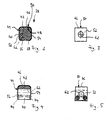
- FIG. 2 shows a side view of a part of the device according to FIG. 1 with an assembly of pressure element and intermediate element
- FIG. 3 shows a side view of the assembly according to FIG. 2 from a viewing direction rotated by 90 °;
- FIG. 4 shows a side view of a further embodiment of an assembly of pressure element and intermediate element
- FIG. 5 shows a side view of the assembly according to FIG. 4 from a viewing direction rotated by 90 °;
- FIG. 6 shows a side view of a further embodiment of a device for finishing machining of a workpiece
- Fig. 7 is a sectional view of the device according to Fig. 6;
- FIG. 8 shows a side view of an embodiment of a finishing device when machining a workpiece with a smaller diameter
- Fig. 9 is a side view corresponding to FIG. 8 when machining a workpiece with a larger diameter.
- An embodiment of a device is used for the processing of a workpiece 12, for example a crankshaft, in a bandfinishing manner.
- the workpiece 12 has a workpiece axis 14 and a workpiece surface 16 to be finish-machined.
- a finishing belt 18 is provided, which abuts along a partial circumference of the workpiece surface 16 at this.
- the workpiece surface 16 is, for example, the bearing seat of a crankshaft.
- a rotary drive moves the workpiece 12 into a rotational movement about the workpiece axis 14.
- An oscillating drive moves the workpiece 12 in parallel to the workpiece axis 14 oscillating in opposite directions.
- the finishing belt 18 produces a cross-cut structure characteristic of the finish-end machining by abrasive abutment of the front side of the finish belt on the workpiece surface 16.
- the device 10 further comprises a carrier 20 for connection to a pressure tong 22 shown in sections in FIGS. 8 and 9.
- the carrier 20 has a pivot bearing 24 for supporting a holding device 26 about a pivot axis 28.
- the holding device 26 is held on the carrier 20 in a pivoting means position, by means of spring units 30 and 32, which are arranged on both sides of the pivot bearing 24 and act as a function of a pivoting direction of the holding device 26 each as a compression spring.
- the holding device 26 has a cup-shaped holding part 34 with receptacles 36 arranged at an angle to one another for receiving an assembly 38 shown individually in FIG.
- the assembly 38 comprises an approximately cuboidal or cube-shaped pressure element 40, for example, with a pressing portion 42 pointing in the direction of the finishing belt 18 when arranged in the receptacle 36.
- the assembly 38 further includes an intermediate member 44 having a blade-shaped portion 46 which cooperates with the pressing portion 42 of the pressing member 40.
- the leaf-shaped section 46 has a force-receiving surface 48 facing the pressing section 42 and a force-transmitting surface 50 facing the rear side of the finishing strip 18.
- the leaf-shaped section 46 is preferably made of a hardened spring steel and preferably has a material thickness of not more than 1 mm, in particular not more than 0.5 mm.
- the intermediate element 44 has, starting from the leaf-shaped portion 46 extending, lateral portions 52 and 54, which surround the pressure element 40 together with the leaf-shaped portion 46.
- undercut sections 56 and 58 extending from the lateral sections 52, 54 may be provided.
- the assemblies 38 are immovably received in the receptacles 36 of the holding device 26. But it is also possible that the assemblies 38 are mounted relative to the holding device 26 about axes 60 movable.
- the axes 60 are perpendicular to the workpiece axis 14 and parallel to a plane in which the force transmission surface 50 of the intermediate member 44 extends. Thus, the assemblies 38 may tilt about the axes 60 and align with the geometry of the workpiece 12. A compensation of axis errors of bearing seats of the workpiece 12 is possible.
- the pressing elements and optionally also the intermediate element 44 have an opening 62 extending parallel to the axis 60, which serve to pass through a bearing pin 64 (shown for example in FIG. 7).
- the holding device 26 also serves for the attachment of tape guide elements 66 and 68 with rounded tape guide surfaces, such as a tape insertion surface 70 and a belt discharge surface 72nd
- fastening elements for example screws 74 (see FIG.
- the finishing belt 18 is pressed against the workpiece surface 16 of the workpiece 12 by means of the assemblies 38.
- a pressing force provided by means of a gun arm 22 is transmitted via the carrier 20 and the holding device 26 to the assemblies 38.
- the pressing member 40 transmits a pressing force by means of the pressing portion 42 on the force receiving surface 48 of the sheet-shaped portion 46 of the intermediate member 44. This in turn transmits the pressing force by means of the force transmission surface 50 on a back of the finishing tape 18, which then with an abrasive front side with the workpiece surface 16 of the Workpiece 12 cooperates.
- the assemblies 38 generate pressing forces acting in the radial direction, that is to say pressing forces which are directed in the direction of the workpiece axes 14 of the workpiece 12.
- the pressing element 40 of the assembly 38 is made, for example, of a plastic material, preferably of an elastomer.
- a suitable plastic is polyester-urethane rubber, which is also known under the trade name "Vulkollan" of Bayer AG, Leverkusen, Germany. It is possible that the entire pressure element 40 is made of a softer material than the intermediate element 44, as shown for example in Figures 1 to 3. But it is also possible that only one pressing portion 42 of the pressing member 40 is made of a softer material than the leaf-shaped portion 46 of the intermediate member 44 (see Figure 4).
- a pressing section 142 is provided, which has a free space 144 facing the force receiving surface 48 of the intermediate element 44.
- the clearance 144 is seen laterally bounded in the course of the finishing belt 18 by elevated portions 146 and allows a flexurally elastic deflection of the intermediate member 44 in the space 144 inside.
- the leaf-shaped portion 46 of the intermediate member 44 extends in an undeformed initial state in a straight plane.
- the leaf-shaped section 46 flexes elastically so that the leaf-shaped section 46 and thus also the force transmission surface 50 curve according to the curvature of the workpiece surface 16. In this way, the contact area between the sheet-shaped section 46 and the finishing belt 18 and thus between the finishing belt 18 and the workpiece surface 16 can be increased.
- an intermediate element 44 is assigned to a pressure element 40 in each case. It is also possible that an intermediate element 44 is provided which is associated with a plurality of pressing elements 40, preferably exactly two pressing elements 40. This will be described below with reference to an embodiment shown in FIGS. 6 and 7.
- An intermediate element 44 which is assigned to a plurality of pressing elements 40, has a number of leaf-shaped sections 46 corresponding to the number of pressing elements 40, for example a first leaf-shaped section 46a and a second leaf-shaped section 46b provided separately therefrom (see FIG.
- the sections 46a and 46b are connected to each other by means of a connecting section 76, which is spaced apart from a workpiece surface 16 to be machined.
- the connecting portion 76 is connected to the holding device 26 by means of a connecting element 78.
- the sections 46a and 46b each have on their side facing away from the connecting portion 76 side end portions 80 and 82, respectively.
- the end-side sections 80 and 82 are likewise arranged at a distance from the workpiece surface 16 to be machined and preferably themselves fixed to the holding device 26, for example by means of the bearing pins 64, which also serve to provide the above-described tilted mounting of the pressing elements 40 relative to the holding device 26.
- the leaf-shaped sections 46a and 46b extend with their respective force transmission surfaces 50 in each case in straight planes. These planes are oriented at an angle of 90 ° +/- 20 °, in particular of 90 ° +/- 10 °, relative to each other. This angular arrangement of the straight planes allows machining of workpieces 12 with different diameters. This is illustrated in FIG. 6 on the basis of a smaller workpiece 12 (I) and on the basis of a larger workpiece 12 (II).
- two of the devices 10 described above are preferably used, which are each connected to a gun arm 22 (see Figures 8 and 9).
- a common finishing belt 18, which is supplied from a finishing belt supply 84 of a first device 10a and via a deflection 86 to a second device 10b and finally to a finishing belt collector 88.
- the pliers arms 22 are pivotally mounted in a conventional manner.
- the forceps arms 22 at the height of the workpiece 12 (I) have a smaller distance relative to one another than when machining a comparatively larger workpiece 12 (II), compare FIGS. 8 and 9.
Landscapes
- Engineering & Computer Science (AREA)
- Mechanical Engineering (AREA)
- Finish Polishing, Edge Sharpening, And Grinding By Specific Grinding Devices (AREA)
Abstract
Priority Applications (3)
| Application Number | Priority Date | Filing Date | Title |
|---|---|---|---|
| BR112015028594-5A BR112015028594B1 (pt) | 2013-05-14 | 2014-03-31 | Dispositivo para a usinagem de acabamento de uma peqa |
| CN201480024936.6A CN105163905B (zh) | 2013-05-14 | 2014-03-31 | 用于带式精加工工件的装置 |
| US14/890,947 US10058971B2 (en) | 2013-05-14 | 2014-03-31 | Device for band finishing a workpiece |
Applications Claiming Priority (2)
| Application Number | Priority Date | Filing Date | Title |
|---|---|---|---|
| EP13167681.9A EP2803445B1 (fr) | 2013-05-14 | 2013-05-14 | Dispositif pour l'usinage de finition à la bande d'une pièce |
| EP13167681.9 | 2013-05-14 |
Publications (1)
| Publication Number | Publication Date |
|---|---|
| WO2014183914A1 true WO2014183914A1 (fr) | 2014-11-20 |
Family
ID=48444145
Family Applications (1)
| Application Number | Title | Priority Date | Filing Date |
|---|---|---|---|
| PCT/EP2014/056396 Ceased WO2014183914A1 (fr) | 2013-05-14 | 2014-03-31 | Dispositif d'usinage de finition d'une pièce au moyen d'une bande |
Country Status (5)
| Country | Link |
|---|---|
| US (1) | US10058971B2 (fr) |
| EP (1) | EP2803445B1 (fr) |
| CN (1) | CN105163905B (fr) |
| BR (1) | BR112015028594B1 (fr) |
| WO (1) | WO2014183914A1 (fr) |
Families Citing this family (2)
| Publication number | Priority date | Publication date | Assignee | Title |
|---|---|---|---|---|
| DE102015216357A1 (de) | 2015-08-27 | 2017-03-02 | Supfina Grieshaber Gmbh & Co. Kg | Umfangsflächenbearbeitungseinheit, Werkzeugmaschine und Verfahren zum Betrieb |
| CN107443217A (zh) * | 2017-08-07 | 2017-12-08 | 周强造 | 一种内衣背扣打磨装置 |
Citations (5)
| Publication number | Priority date | Publication date | Assignee | Title |
|---|---|---|---|---|
| EP0161748A2 (fr) | 1984-05-07 | 1985-11-21 | Industrial Metal Products Corporation | Appareil et procédé pour le microfinissage de surfaces |
| DE4419366A1 (de) | 1994-06-03 | 1995-12-07 | Otmar Fahrion | Finishmaschine |
| DE10332605A1 (de) * | 2003-07-17 | 2005-02-17 | Ibz Gmbh | Anpressvorrichtung für eine Oberflächenbearbeitungsvorrichtung |
| DE202010006480U1 (de) | 2010-04-30 | 2010-08-05 | Nagel Maschinen- Und Werkzeugfabrik Gmbh | Andrückeinrichtung zum Andrücken von Schneidmittel, Trägerkassette für eine solche Andrückeinrichtung sowie Vorrichtung mit einer solchen Andrückeinrichtung |
| EP2212058B1 (fr) | 2007-10-16 | 2011-07-13 | Nagel Maschinen- und Werkzeugfabrik GmbH | Dispositif de pression d'éléments coupants, dispositif et procédé de finition de surfaces périphériques de parties cylindriques de pièces d'usinage |
Family Cites Families (4)
| Publication number | Priority date | Publication date | Assignee | Title |
|---|---|---|---|---|
| DE2320345A1 (de) * | 1973-04-21 | 1974-11-07 | Karl Heesemann | Bandschleifmaschine |
| DE19622116C2 (de) | 1995-07-22 | 2000-08-03 | Federal Mogul Burscheid Gmbh | Kurzhub-Bandhonen von Kolbenringlaufflächen |
| US20020086627A1 (en) * | 2001-01-03 | 2002-07-04 | Andrews William L. | Flex plate attachment for use with belt sanders |
| CN102781625B (zh) | 2011-02-24 | 2015-08-12 | 日本精工株式会社 | 内外轮兼用超精加工盘 |
-
2013
- 2013-05-14 EP EP13167681.9A patent/EP2803445B1/fr active Active
-
2014
- 2014-03-31 CN CN201480024936.6A patent/CN105163905B/zh active Active
- 2014-03-31 BR BR112015028594-5A patent/BR112015028594B1/pt active IP Right Grant
- 2014-03-31 US US14/890,947 patent/US10058971B2/en active Active
- 2014-03-31 WO PCT/EP2014/056396 patent/WO2014183914A1/fr not_active Ceased
Patent Citations (5)
| Publication number | Priority date | Publication date | Assignee | Title |
|---|---|---|---|---|
| EP0161748A2 (fr) | 1984-05-07 | 1985-11-21 | Industrial Metal Products Corporation | Appareil et procédé pour le microfinissage de surfaces |
| DE4419366A1 (de) | 1994-06-03 | 1995-12-07 | Otmar Fahrion | Finishmaschine |
| DE10332605A1 (de) * | 2003-07-17 | 2005-02-17 | Ibz Gmbh | Anpressvorrichtung für eine Oberflächenbearbeitungsvorrichtung |
| EP2212058B1 (fr) | 2007-10-16 | 2011-07-13 | Nagel Maschinen- und Werkzeugfabrik GmbH | Dispositif de pression d'éléments coupants, dispositif et procédé de finition de surfaces périphériques de parties cylindriques de pièces d'usinage |
| DE202010006480U1 (de) | 2010-04-30 | 2010-08-05 | Nagel Maschinen- Und Werkzeugfabrik Gmbh | Andrückeinrichtung zum Andrücken von Schneidmittel, Trägerkassette für eine solche Andrückeinrichtung sowie Vorrichtung mit einer solchen Andrückeinrichtung |
Also Published As
| Publication number | Publication date |
|---|---|
| EP2803445B1 (fr) | 2015-07-08 |
| US10058971B2 (en) | 2018-08-28 |
| CN105163905B (zh) | 2016-08-24 |
| BR112015028594A2 (pt) | 2017-07-25 |
| EP2803445A1 (fr) | 2014-11-19 |
| BR112015028594B1 (pt) | 2020-11-24 |
| CN105163905A (zh) | 2015-12-16 |
| US20160101496A1 (en) | 2016-04-14 |
Similar Documents
| Publication | Publication Date | Title |
|---|---|---|
| EP3206837B1 (fr) | Disque à polir pour un outil destiné au traitement précis de surfaces optiques actives en particulier sur des verres de lunettes | |
| EP1990133B1 (fr) | Agrégat de ponçage comme outil pour un dispositif de traitement | |
| EP3459679B1 (fr) | Dispositif de production d'un finissage non défini sur une surface d'une pièce à usiner métallique dans un processus en continu | |
| DE102014222848B4 (de) | Finishvorrichtung | |
| DE102019005084A1 (de) | Polierwerkzeug sowie Vorrichtung zum Polieren eines Werkstücks | |
| EP1554068A1 (fr) | Dispositif d'arrachage | |
| WO2015104372A1 (fr) | Dispositif de compression | |
| EP2803445B1 (fr) | Dispositif pour l'usinage de finition à la bande d'une pièce | |
| WO2007031145A1 (fr) | Tourelle d'outil | |
| EP1878534A1 (fr) | Dispositif pour orienter une broche porte-outil comprenant une charnière | |
| DE102014208319B4 (de) | Bandfinishvorrichtung und Verfahren zum Betrieb einer Bandfinishvorrichtung | |
| EP3423233A1 (fr) | Outil de brunissage | |
| DE102015115313B4 (de) | Schleifwerkzeug und dessen Verwendung zur computergesteuerten Nachbearbeitung gefräster Freiformflächen | |
| DE102019129756A1 (de) | Steuervorrichtung für eine Arbeitsmaschine | |
| DE102017201120B3 (de) | Andrückeinrichtung für Finishband und Bandfinishvorrichtung | |
| EP3969224B1 (fr) | Ponceuse orbitale pourvue d'un dispositif de freinage | |
| DE102014200445A1 (de) | Andrückeinrichtung | |
| EP2399706B1 (fr) | Dispositif de finissage pour le finissage de surfaces de pièces usinées | |
| DE102014102282B4 (de) | Finishwerkzeugträger und Finisheinheit | |
| DE102019103677A1 (de) | Finishvorrichtung und Verfahren zur Finishbearbeitung eines Werkstücks | |
| DE102016205658B3 (de) | Schneidwerkzeug mit einem an einem trägerkörper durch eine spannpratze lösbar befestigtem schneidkörper | |
| EP3524386B1 (fr) | Dispositif de soutien d'une pièce à usiner | |
| EP3020506B1 (fr) | Unité de machine-outil destinée à l'alignement d'un outil ou d'une pièce à usiner | |
| DE202015101725U1 (de) | Oszillationswerkzeug und Werkzeugmaschine zum Bearbeiten eines Werkstücks | |
| DE4329781C2 (de) | Steinhalter für wenigstens einen Honstein |
Legal Events
| Date | Code | Title | Description |
|---|---|---|---|
| WWE | Wipo information: entry into national phase |
Ref document number: 201480024936.6 Country of ref document: CN |
|
| 121 | Ep: the epo has been informed by wipo that ep was designated in this application |
Ref document number: 14713850 Country of ref document: EP Kind code of ref document: A1 |
|
| WWE | Wipo information: entry into national phase |
Ref document number: 14890947 Country of ref document: US |
|
| NENP | Non-entry into the national phase |
Ref country code: DE |
|
| REG | Reference to national code |
Ref country code: BR Ref legal event code: B01A Ref document number: 112015028594 Country of ref document: BR |
|
| 122 | Ep: pct application non-entry in european phase |
Ref document number: 14713850 Country of ref document: EP Kind code of ref document: A1 |
|
| ENP | Entry into the national phase |
Ref document number: 112015028594 Country of ref document: BR Kind code of ref document: A2 Effective date: 20151113 |