WO2014184883A1 - Système de climatisation - Google Patents
Système de climatisation Download PDFInfo
- Publication number
- WO2014184883A1 WO2014184883A1 PCT/JP2013/063466 JP2013063466W WO2014184883A1 WO 2014184883 A1 WO2014184883 A1 WO 2014184883A1 JP 2013063466 W JP2013063466 W JP 2013063466W WO 2014184883 A1 WO2014184883 A1 WO 2014184883A1
- Authority
- WO
- WIPO (PCT)
- Prior art keywords
- temperature
- value
- indoor
- evaporation temperature
- heat exchanger
- Prior art date
- Legal status (The legal status is an assumption and is not a legal conclusion. Google has not performed a legal analysis and makes no representation as to the accuracy of the status listed.)
- Ceased
Links
Images






Classifications
-
- F—MECHANICAL ENGINEERING; LIGHTING; HEATING; WEAPONS; BLASTING
- F24—HEATING; RANGES; VENTILATING
- F24F—AIR-CONDITIONING; AIR-HUMIDIFICATION; VENTILATION; USE OF AIR CURRENTS FOR SCREENING
- F24F3/00—Air-conditioning systems in which conditioned primary air is supplied from one or more central stations to distributing units in the rooms or spaces where it may receive secondary treatment; Apparatus specially designed for such systems
- F24F3/06—Air-conditioning systems in which conditioned primary air is supplied from one or more central stations to distributing units in the rooms or spaces where it may receive secondary treatment; Apparatus specially designed for such systems characterised by the arrangements for the supply of heat-exchange fluid for the subsequent treatment of primary air in the room units
-
- F—MECHANICAL ENGINEERING; LIGHTING; HEATING; WEAPONS; BLASTING
- F24—HEATING; RANGES; VENTILATING
- F24F—AIR-CONDITIONING; AIR-HUMIDIFICATION; VENTILATION; USE OF AIR CURRENTS FOR SCREENING
- F24F1/00—Room units for air-conditioning, e.g. separate or self-contained units or units receiving primary air from a central station
- F24F1/0003—Room units for air-conditioning, e.g. separate or self-contained units or units receiving primary air from a central station characterised by a split arrangement, wherein parts of the air-conditioning system, e.g. evaporator and condenser, are in separately located units
-
- F—MECHANICAL ENGINEERING; LIGHTING; HEATING; WEAPONS; BLASTING
- F24—HEATING; RANGES; VENTILATING
- F24F—AIR-CONDITIONING; AIR-HUMIDIFICATION; VENTILATION; USE OF AIR CURRENTS FOR SCREENING
- F24F1/00—Room units for air-conditioning, e.g. separate or self-contained units or units receiving primary air from a central station
- F24F1/0007—Indoor units, e.g. fan coil units
- F24F1/0035—Indoor units, e.g. fan coil units characterised by introduction of outside air to the room
-
- F—MECHANICAL ENGINEERING; LIGHTING; HEATING; WEAPONS; BLASTING
- F24—HEATING; RANGES; VENTILATING
- F24F—AIR-CONDITIONING; AIR-HUMIDIFICATION; VENTILATION; USE OF AIR CURRENTS FOR SCREENING
- F24F11/00—Control or safety arrangements
- F24F11/0001—Control or safety arrangements for ventilation
-
- F—MECHANICAL ENGINEERING; LIGHTING; HEATING; WEAPONS; BLASTING
- F24—HEATING; RANGES; VENTILATING
- F24F—AIR-CONDITIONING; AIR-HUMIDIFICATION; VENTILATION; USE OF AIR CURRENTS FOR SCREENING
- F24F11/00—Control or safety arrangements
- F24F11/0008—Control or safety arrangements for air-humidification
-
- F—MECHANICAL ENGINEERING; LIGHTING; HEATING; WEAPONS; BLASTING
- F24—HEATING; RANGES; VENTILATING
- F24F—AIR-CONDITIONING; AIR-HUMIDIFICATION; VENTILATION; USE OF AIR CURRENTS FOR SCREENING
- F24F11/00—Control or safety arrangements
- F24F11/89—Arrangement or mounting of control or safety devices
-
- F—MECHANICAL ENGINEERING; LIGHTING; HEATING; WEAPONS; BLASTING
- F24—HEATING; RANGES; VENTILATING
- F24F—AIR-CONDITIONING; AIR-HUMIDIFICATION; VENTILATION; USE OF AIR CURRENTS FOR SCREENING
- F24F12/00—Use of energy recovery systems in air conditioning, ventilation or screening
- F24F12/001—Use of energy recovery systems in air conditioning, ventilation or screening with heat-exchange between supplied and exhausted air
- F24F12/006—Use of energy recovery systems in air conditioning, ventilation or screening with heat-exchange between supplied and exhausted air using an air-to-air heat exchanger
-
- F—MECHANICAL ENGINEERING; LIGHTING; HEATING; WEAPONS; BLASTING
- F24—HEATING; RANGES; VENTILATING
- F24F—AIR-CONDITIONING; AIR-HUMIDIFICATION; VENTILATION; USE OF AIR CURRENTS FOR SCREENING
- F24F3/00—Air-conditioning systems in which conditioned primary air is supplied from one or more central stations to distributing units in the rooms or spaces where it may receive secondary treatment; Apparatus specially designed for such systems
- F24F3/06—Air-conditioning systems in which conditioned primary air is supplied from one or more central stations to distributing units in the rooms or spaces where it may receive secondary treatment; Apparatus specially designed for such systems characterised by the arrangements for the supply of heat-exchange fluid for the subsequent treatment of primary air in the room units
- F24F3/065—Air-conditioning systems in which conditioned primary air is supplied from one or more central stations to distributing units in the rooms or spaces where it may receive secondary treatment; Apparatus specially designed for such systems characterised by the arrangements for the supply of heat-exchange fluid for the subsequent treatment of primary air in the room units with a plurality of evaporators or condensers
-
- F—MECHANICAL ENGINEERING; LIGHTING; HEATING; WEAPONS; BLASTING
- F24—HEATING; RANGES; VENTILATING
- F24F—AIR-CONDITIONING; AIR-HUMIDIFICATION; VENTILATION; USE OF AIR CURRENTS FOR SCREENING
- F24F3/00—Air-conditioning systems in which conditioned primary air is supplied from one or more central stations to distributing units in the rooms or spaces where it may receive secondary treatment; Apparatus specially designed for such systems
- F24F3/12—Air-conditioning systems in which conditioned primary air is supplied from one or more central stations to distributing units in the rooms or spaces where it may receive secondary treatment; Apparatus specially designed for such systems characterised by the treatment of the air otherwise than by heating and cooling
- F24F3/14—Air-conditioning systems in which conditioned primary air is supplied from one or more central stations to distributing units in the rooms or spaces where it may receive secondary treatment; Apparatus specially designed for such systems characterised by the treatment of the air otherwise than by heating and cooling by humidification; by dehumidification
-
- F—MECHANICAL ENGINEERING; LIGHTING; HEATING; WEAPONS; BLASTING
- F24—HEATING; RANGES; VENTILATING
- F24F—AIR-CONDITIONING; AIR-HUMIDIFICATION; VENTILATION; USE OF AIR CURRENTS FOR SCREENING
- F24F7/00—Ventilation
- F24F7/04—Ventilation with ducting systems, e.g. by double walls; with natural circulation
- F24F7/06—Ventilation with ducting systems, e.g. by double walls; with natural circulation with forced air circulation, e.g. by fan positioning of a ventilator in or against a conduit
- F24F7/08—Ventilation with ducting systems, e.g. by double walls; with natural circulation with forced air circulation, e.g. by fan positioning of a ventilator in or against a conduit with separate ducts for supplied and exhausted air with provisions for reversal of the input and output systems
-
- Y—GENERAL TAGGING OF NEW TECHNOLOGICAL DEVELOPMENTS; GENERAL TAGGING OF CROSS-SECTIONAL TECHNOLOGIES SPANNING OVER SEVERAL SECTIONS OF THE IPC; TECHNICAL SUBJECTS COVERED BY FORMER USPC CROSS-REFERENCE ART COLLECTIONS [XRACs] AND DIGESTS
- Y02—TECHNOLOGIES OR APPLICATIONS FOR MITIGATION OR ADAPTATION AGAINST CLIMATE CHANGE
- Y02B—CLIMATE CHANGE MITIGATION TECHNOLOGIES RELATED TO BUILDINGS, e.g. HOUSING, HOUSE APPLIANCES OR RELATED END-USER APPLICATIONS
- Y02B30/00—Energy efficient heating, ventilation or air conditioning [HVAC]
- Y02B30/56—Heat recovery units
Definitions
- the present invention relates to an air conditioning harmony system including an air conditioner and a ventilator.
- the ventilator performs an operation of replacing indoor air with fresh outdoor air, and when cooling, when the enthalpy of air introduced from the outside air is high It becomes a cooling load (outside air load).
- Other heat loads include an indoor load generated indoors and a housing load entering from a building wall.
- the latent heat load has been processed with the refrigerant evaporation temperature of the indoor heat exchanger of the air conditioner kept constant at a low temperature.
- the operation in which the evaporation temperature is kept constant at a low temperature and the latent heat load is processed there is a problem that the operation efficiency is lowered.
- the operation efficiency is improved, but there is a problem that the amount of latent heat treatment is insufficient, the indoor humidity is increased, and the comfort is lowered.
- the ventilator and the air conditioner that perform outside air processing are controlled independently, and the evaporation temperature of the indoor heat exchanger of the air conditioner is controlled to be equal to or higher than the dew point temperature of the indoor air to mainly process the sensible heat load.
- a latent sensible and separated air conditioning system that sets an evaporation temperature that secures a necessary dehumidification amount with a ventilator that performs outside air processing and mainly processes a latent heat load (for example, Patent Document 1).
- the sensible heat is controlled by controlling the refrigeration cycle in each of the air conditioner and the ventilator and adjusting the evaporation temperature of each evaporator.
- the load and latent heat load are shared, the evaporating temperature of the ventilator is set based on the required dehumidification amount, and the evaporating temperature of the indoor heat exchanger of the air conditioner is set above the dew point temperature. It was a single setting method. For this reason, there has been a problem that it is impossible to set an appropriate evaporating temperature in consideration of the outside air temperature humidity condition, the indoor temperature humidity condition, and the like in the respective evaporators of the air conditioner and the ventilator.
- the present invention has been made in order to solve the conventional method for setting an appropriate evaporation temperature of an evaporator, and considers outdoor air load, and comfort due to insufficient amount of latent heat treatment (insufficient dehumidification). It aims at providing the air conditioning system which implement
- An air conditioning system has a refrigerant system composed of an outdoor unit in which refrigerant circulates, an indoor unit, and a ventilator, and the refrigerant system includes a compressor, an outdoor heat exchanger, a first expansion valve, It has an indoor heat exchanger, a second expansion valve, and a ventilator cooler, and the indoor unit has the first expansion valve and the indoor heat exchanger, and circulates indoor air while adjusting the temperature.
- the ventilator has the second expansion valve and the ventilator cooler, and is configured to exchange indoor air and outdoor air, and to cool and dehumidify the outdoor air with the ventilator cooler,
- the outdoor unit, the indoor unit, and the ventilator are connected by a refrigerant pipe and have means for detecting the temperature and humidity of outdoor air, and the indoor heat exchanger and the ventilator are cooled according to the outdoor air temperature and humidity.
- the maximum and minimum evaporating temperature setpoints The evaporating temperature set values of the indoor heat exchanger and the ventilator cooler are set between the maximum evaporating temperature set value and the minimum evaporating temperature set value, and the indoor heat exchanger and the ventilator cooling
- the evaporation temperature of the vessel is controlled so as to become the evaporation temperature set value.
- the evaporating temperature set values of the indoor heat exchanger and the ventilator cooler are set in a range between the maximum evaporating temperature set value and the minimum evaporating temperature set value that are changed based on the outside air temperature and humidity conditions. Therefore, it is possible to set the evaporating temperature setting value with a predetermined control width assuming the sensible heat load and the latent heat load from the outside air temperature and humidity conditions. Therefore, it becomes easy to follow load fluctuations, realize latent heat treatment and sensible heat treatment at an appropriate evaporation temperature, and ensure energy saving while maintaining comfort.
- FIG. 1 It is a schematic diagram of an air-conditioning system in the present invention. It is a refrigerant circuit figure at the time of air_conditionaing
- FIG. 1 is a schematic diagram of an air conditioning system according to the first embodiment.
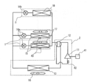
- the air conditioning system 100 one or a plurality of indoor units 1 and one or a plurality of ventilators 3 are connected by an outdoor unit 2 and a refrigerant pipe 104.
- the indoor unit 1, the outdoor unit 2, and the ventilator 3 are connected to the centralized controller 102 through the transmission line 103.
- the centralized controller 102 is provided with target temperature / humidity setting means 44 (not shown).
- FIG. 2 is a refrigerant circuit diagram of the air-conditioning system according to Embodiment 1.
- the refrigerant system circuit includes a compressor 11, a four-way valve 12, an outdoor heat exchanger 13, a first expansion valve 14a, an indoor heat exchanger 15, a second expansion valve 14b, and a ventilator cooler 18.
- the indoor unit 1 includes a first expansion valve 14a, an indoor heat exchanger 15, and an indoor heat exchanger blower 17, and one or more indoor units 1 are installed.
- the ventilator 3 includes a second expansion valve 14b and a ventilator cooler 18, and one or a plurality of ventilators 3 are installed.
- FIG. 3 is a schematic configuration diagram of the ventilation device 3 of the air-conditioning system according to the first embodiment.
- the outdoor air (OA) after the total heat exchange is supplied to the room as supply air (SA), and the indoor air (RA) after the total heat exchange is exhausted to the outside as exhaust air (EA).
- SA supply air
- EA exhaust air
- FIG. 4 is a refrigerant circuit diagram of the air-conditioning system according to Embodiment 1. As shown in FIG. 4, compressor frequency adjusting means 41 and evaporation temperature detecting means 42 are provided, and each indoor unit 1 is provided with suction temperature and humidity detecting means 43.
- FIG. 5 is a diagram showing the evaporating temperature set value Te of the indoor heat exchanger 15 or the ventilator cooler 18 of the ventilator 3 in the first embodiment.
- the vertical axis represents the evaporation temperature set value Te of the indoor heat exchanger 15 or the ventilator cooler 18 of the ventilator 3, and the horizontal axis represents the target temperature / humidity setting means from the indoor temperature Ta detected by the suction temperature / humidity detection means 43.
- ⁇ T which is a temperature difference obtained by subtracting the indoor target temperature Ta_tgt set in 44.
- Te_max represents the maximum evaporation temperature that is the maximum value of the evaporation temperature set value Te
- Te_min represents the minimum evaporation temperature that is the minimum value of the evaporation temperature set value Te.
- the evaporation temperature of the indoor heat exchanger 15 or the ventilator cooler 18 is determined between the maximum evaporation temperature Te_max and the minimum evaporation temperature Te_min according to ⁇ T which is a temperature difference obtained by subtracting the indoor target temperature Ta_tgt from the indoor temperature Ta. It is adjusted by changing the operating frequency of the compressor 11 by the compressor frequency adjusting means 41 and adjusting the opening degree of the expansion valve 14 so that the evaporation temperature set value Te is obtained.
- FIG. 6 shows a setting range of the evaporation temperature set value Te for one indoor unit system and three ventilator systems in the first embodiment.
- the maximum evaporation temperature Te_max and the minimum evaporation temperature Te_min of the indoor heat exchanger 15 of the indoor unit system 1 and the ventilator cooler 18 of the ventilation system 3 are ET_max.
- the maximum evaporating temperature Te_max and the minimum evaporating temperature Te_min have two patterns of values of Hi level with a high evaporating temperature and Lo level with a low evaporating temperature in the indoor heat exchanger 15 and the ventilator cooler 18, respectively.
- the maximum evaporation temperature when the indoor heat exchanger 15 is at a high evaporation level Hi level is ETi_hi_max
- the minimum evaporation temperature is ETi_hi_min
- the maximum evaporation temperature when the evaporation temperature is low Lo is ETi_lo_max
- the minimum evaporation temperature is ETi_lo_min.
- the maximum evaporation temperature when the ventilator cooler 18 is at a high evaporation level Hi level is ETv_hi_max
- the minimum evaporation temperature is ETv_hi_min
- the maximum evaporation temperature when the evaporation temperature is low Lo level is ETv_lo_max
- the minimum evaporation temperature is ETv_lo_min.
- ETi_hi_max 14 ° C.
- ETv_hi_max 12 ° C.
- ETi_hi_min 9 ° C.
- ETv_hi_min 7 ° C.
- ETi_lo_max 9 ° C.
- ETv_lo_max 7 ° C.
- ETi_lo_min 2 ° C.
- ETv_lo_min 0 ° C.
- the sensible heat load and the latent heat load can be more appropriately processed by setting the maximum evaporation temperature ET_max and the minimum evaporation temperature ET_min of the indoor heat exchanger 15 and the ventilator cooler 18 to optimum values, respectively. It becomes possible.
- the switching between the Hi level and the Lo level of the evaporation temperature is determined by the outside air temperature and humidity conditions so that one indoor unit system is a sensible heat treatment main body, and three ventilation devices are a sensible heat treatment + latent heat treatment.
- the detection value of the OA temperature / humidity detection means 31 of the ventilator 3 is used as the outside air temperature humidity.
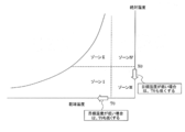
- FIG. 7 is an air diagram in which the conditions of the outside air sucked into the ventilation device 3 are divided into four zones with the dry bulb temperature T0 and the absolute humidity X0 as boundaries.
- the detected value of the OA temperature / humidity detecting means 31 of the ventilator 3 is in zone I, the outside air is at a low temperature / low humidity, and therefore, a low sensible heat / low latent heat load condition is satisfied.
- Zone II since the outside air is low temperature / high humidity, it is a low sensible heat / high latent heat load condition.
- Zone III since the outside air is high temperature / low humidity, it becomes a high sensible heat / low latent heat load condition.
- zone IV since the outside air is high temperature / high humidity, it becomes a high sensible heat / high latent heat load condition.
- the evaporation temperature set value Te is determined as shown in FIG. 5 according to ⁇ T which is a temperature difference.
- ⁇ T is the temperature difference between the indoor temperature Ta and the indoor target temperature Ta_tgt.
- a temperature set value Te is determined.
- the evaporation temperature level in FIG. 6 needs to be the Lo level.
- the latent heat load is low, dehumidification does not become insufficient even if the evaporation temperature of the ventilator cooler 18 that processes the latent heat load is increased, but it is a high sensible heat load.
- the evaporation temperature of the indoor heat exchanger 15 mainly composed of sensible heat is raised, insufficient cooling occurs. That is, the evaporation temperature level in FIG. 6 needs to be the Lo level.
- the sensible heat load is high. Therefore, if the evaporation temperature of the indoor heat exchanger 15 is increased, the cooling becomes insufficient, and the high latent heat load results. Insufficient dehumidification occurs when the evaporation temperature of the vessel 18 is raised. That is, the evaporation temperature level in FIG. 6 needs to be the Lo level.
- the evaporation temperature set value Te is determined as shown in FIG. 5 according to ⁇ T which is a temperature difference obtained by subtracting.
- the evaporation temperature set value Te is determined as shown in FIG.
- Te ET_max when ⁇ T is 0
- Te ET_min when ⁇ T is T1
- the evaporation temperature set value Te is determined to be proportional to ⁇ T between ET_max and ET_min. Is done. From the above, the evaporation temperature levels Hi and Lo are determined by being divided into zones I to IV as shown in FIG. 8 according to the outside air conditions.
- the dry bulb temperature T0 and the absolute humidity X0 which are the threshold values for each zone, are determined as follows.
- T0 and X0 are the maximum outside air temperature and the maximum outside air absolute humidity at which the sensible heat load and the latent heat load can be processed when the operation evaporation temperature is the Hi level minimum evaporation temperature ET_min. That is, if the outside air temperature is T0 and the outside air absolute humidity is X0 or less, it is set as the threshold value of the outside air condition that can process the sensible heat load and the latent heat load at the Hi level minimum evaporating temperature and reach the target indoor temperature and humidity.
- T0 and X0 may be calculated using values assumed for each property.
- T0 and X0 can be determined according to the capacity ratio between the indoor heat exchanger 15 of the connected indoor unit 1 and the ventilator cooler 18 of the ventilator 3. As shown in FIG. 9, the higher the capacity ratio of the ventilator cooler 18 than the indoor heat exchanger 15 is, the higher the ability to handle the sensible heat load and the latent heat load than when the capacity ratio is low. It can be set to a value. In this way, T0 and X0 may be determined according to the capacity ratio between the indoor heat exchanger 15 and the ventilator cooler 18.
- the air volume of the ventilator 3 when the air volume of the ventilator 3 is increased, by setting the values of T0 and X0 high, the evaporation temperature region where the evaporation temperature level is the Hi level is increased, and the energy saving effect is enhanced.
- the air volume of the ventilator 3 decreases, by setting the values of T0 and X0 low, it becomes possible to avoid insufficient cooling and insufficient dehumidification.
- the dry bulb temperature T0 and the absolute humidity X0 which are the threshold values of each zone may be changed as shown in FIG. 10 according to the set values of the target temperature and humidity setting means 44.
- the indoor target temperature / humidity changes, the sensible heat load and the latent heat load change even under the same outside air conditions, so that T0 and X0 change.
- the indoor target temperature Ta_tgt is lowered, the sensible heat load is increased, so that T0 is also lowered.
- the indoor target absolute humidity Xa_tgt is lowered, the latent heat load is increased, so that X0 is also lowered.
- control for switching the evaporation temperature level from the Hi level to the Lo level may be performed using the detected value of the indoor temperature and humidity.
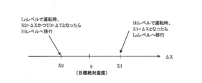
- the difference ⁇ T obtained by subtracting the indoor target temperature Ta_tgt set by the target temperature / humidity setting means 44 from the indoor temperature Ta detected by the suction temperature / humidity detection means 43 as shown in FIG.
- the indoor target absolute humidity Xa_tgt set by the target temperature / humidity setting means 44 is subtracted from the indoor absolute humidity Xa detected by the suction temperature / humidity detection means 43.
- the difference ⁇ T obtained by subtracting the indoor target temperature Ta_tgt from the indoor temperature Ta is smaller than T3 (negative value), and FIG.
- the difference ⁇ X obtained by subtracting the indoor target temperature Ta_tgt from the indoor temperature Ta is smaller than a predetermined value X2 (0> X2), the sensible heat load and the latent heat load are excessively processed. It is determined that the evaporation temperature can be set high, and the evaporation temperature level is shifted from the Lo level to the Hi level. When the compressor is thermo-off during the Lo level operation, it may be shifted to the Hi level.
- the detection values of the RA temperature / humidity detection means 32 provided in the ventilation device 3 may be used.
- FIG. 13 shows an evaporation temperature control flow chart using the difference ⁇ T obtained by subtracting the indoor target temperature Ta_tgt from the room temperature Ta and the difference ⁇ X obtained by subtracting the indoor target absolute humidity Xa_tgt from the indoor absolute humidity Xa as control parameters.
- the temperature / humidity of the outside air is detected by the OA temperature / humidity detecting means 31 in S-1.
- S-2 determination of zone I to zone IV in FIG. 7 is performed according to the detected outside air temperature humidity.
- the evaporation temperature level (Hi level or Lo level) of the indoor heat exchanger 15 of the indoor unit 1 system and the ventilator cooler 18 of the 3 ventilation systems is determined based on FIG.
- a difference ⁇ T is calculated by subtracting the indoor target temperature Ta_tgt from the indoor temperature Ta
- a difference ⁇ X is calculated by subtracting the indoor target absolute humidity Xa_tgt from the indoor absolute humidity Xa.
- the evaporation temperature set value Te is determined based on FIG.
- the difference ⁇ T obtained by subtracting the indoor target temperature Ta_tgt from the indoor temperature Ta is T3 or more and T2 or less in FIG. 11, and the difference ⁇ X obtained by subtracting the indoor target absolute humidity Xa_tgt from the indoor absolute humidity Xa is shown in FIG.
- step S-7 it is determined whether ⁇ T is smaller than T3 and ⁇ X is smaller than X2, and if the condition is not satisfied, the process proceeds to S-8, and if the condition is satisfied, the process proceeds to S-9. If the process proceeds to S-8, it is determined whether ⁇ T is greater than T2 or ⁇ X is greater than X1, and if the condition is not satisfied, the process proceeds to S-13, and the end of operation is determined as described above. To do. If the condition is satisfied in S-8, the process proceeds to S-10, where it is determined whether the evaporation temperature of the indoor heat exchanger 15 is Hi level. If the condition is satisfied, the temperature or humidity reaches the indoor target temperature and humidity. In step S-12, the evaporating temperature level of the indoor heat exchanger 15 is changed to the Lo level. When the condition is not satisfied in S-10 and after proceeding to S-12, the process proceeds to S-13, and the end of operation is determined as described above.
- the process proceeds from S-7 to S-9, it is determined whether the evaporation temperature of the indoor heat exchanger 15 is at the Lo level. If the condition is satisfied, the process proceeds to S-11 and the evaporation temperature of the indoor heat exchanger 15 is determined. Change the level to Hi level. If the condition is not satisfied in S-9, the process proceeds to S-13, and the end of operation is determined as described above.
- the sensible heat load and the latent heat load are assumed from the outside air temperature humidity, and after determining the optimum evaporating temperature of the indoor heat exchanger 15 and the ventilator cooler 18 in the feedforward, the indoor temperature humidity Since the optimum evaporating temperature of the indoor heat exchanger 15 is corrected by feedback control using, the time required to find the optimum evaporating temperature is short, it is possible to follow load fluctuations, and the energy saving effect is enhanced.
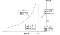
- Embodiment 2 the air diagram is divided into four zones with the dry air temperature T0 and the absolute humidity X0 as boundaries as shown in FIGS. 7 and 8, and in the same zone, the indoor heat exchanger 15 and the ventilation device are divided.
- the evaporation temperature level of the cooler 18 is set to a common Hi level or Lo level, in this embodiment, the evaporation temperature levels of the indoor heat exchanger 15 and the ventilator cooler 18 are set as shown in FIG. To do.
- Other components and evaporation temperature control are the same as those in the first embodiment.
- the evaporation temperature level in FIG. 6 can be set to the Hi level for both the indoor heat exchanger 15 and the ventilator cooler 18.
- the evaporating temperature level in FIG. 6 needs to be the Hi level for the indoor heat exchanger 15 and the Lo level for the ventilator cooler 18.
- the load is low. Therefore, even if the evaporation temperature of the ventilator cooler 18 that processes the latent heat load is increased, the dehumidification does not become insufficient, but the high sensible heat load.
- the evaporation temperature of the indoor heat exchanger 15 mainly composed of sensible heat is raised, insufficient cooling occurs. That is, the evaporation temperature level in FIG. 6 needs to be set to Lo level in the indoor heat exchanger 15, and the ventilator cooler 18 can be set to Hi level.
- the sensible heat load is high. Therefore, if the evaporation temperature of the indoor heat exchanger 15 is increased, the cooling becomes insufficient and the latent heat load is processed. Insufficient dehumidification occurs when the evaporation temperature of 18 is increased. That is, the evaporation temperature level in FIG. 6 needs to set both the indoor heat exchanger 15 and the ventilator cooler 18 to the Lo level.
- the sensible heat load and the latent heat load are more appropriately set by individually setting the evaporation temperature levels of the indoor heat exchanger 15 and the ventilator cooler 18 to the Hi level and the Lo level. Can be processed.
- the ET_max and ET_min are determined with the evaporation temperature level being the Hi level and the Lo level.
- a fixed value may be set such as fixed.
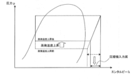
- the control according to Embodiments 1 and 2 makes it possible to achieve an optimal evaporation temperature according to the load. That is, the evaporating temperature set value Te can be increased while reliably processing the sensible heat load and the latent heat load, and as shown in FIG. 15, the compressor input is reduced and energy is saved. Moreover, since excessive processing of the sensible heat load and the latent heat load can be suppressed, the load is reduced and the energy saving effect is increased.
- the load is determined by detecting the outside air temperature and humidity, when it is determined that the load is low, it is possible to operate at a high evaporation temperature even at the start of operation. Energy saving effect at the time of cooling (during pull-down) can also be obtained.
- the evaporation temperature level is divided into a Hi level and a Lo level, but it may be divided into three or more.
- the target loss startsing / stopping loss
- the target SH superheat degree
Landscapes
- Engineering & Computer Science (AREA)
- Chemical & Material Sciences (AREA)
- Combustion & Propulsion (AREA)
- Mechanical Engineering (AREA)
- General Engineering & Computer Science (AREA)
- Air Conditioning Control Device (AREA)
- Central Air Conditioning (AREA)
Abstract
Priority Applications (5)
| Application Number | Priority Date | Filing Date | Title |
|---|---|---|---|
| PCT/JP2013/063466 WO2014184883A1 (fr) | 2013-05-14 | 2013-05-14 | Système de climatisation |
| GB201519232A GB2529329B (en) | 2013-05-14 | 2013-05-14 | Air conditioning system |
| JP2015516805A JP5996107B2 (ja) | 2013-05-14 | 2013-05-14 | 空気調和システム |
| US14/888,715 US9874360B2 (en) | 2013-05-14 | 2013-05-14 | Air-conditioning system |
| CN201420142256.1U CN203823945U (zh) | 2013-05-14 | 2014-03-27 | 空气调节系统 |
Applications Claiming Priority (1)
| Application Number | Priority Date | Filing Date | Title |
|---|---|---|---|
| PCT/JP2013/063466 WO2014184883A1 (fr) | 2013-05-14 | 2013-05-14 | Système de climatisation |
Publications (1)
| Publication Number | Publication Date |
|---|---|
| WO2014184883A1 true WO2014184883A1 (fr) | 2014-11-20 |
Family
ID=51479435
Family Applications (1)
| Application Number | Title | Priority Date | Filing Date |
|---|---|---|---|
| PCT/JP2013/063466 Ceased WO2014184883A1 (fr) | 2013-05-14 | 2013-05-14 | Système de climatisation |
Country Status (5)
| Country | Link |
|---|---|
| US (1) | US9874360B2 (fr) |
| JP (1) | JP5996107B2 (fr) |
| CN (1) | CN203823945U (fr) |
| GB (1) | GB2529329B (fr) |
| WO (1) | WO2014184883A1 (fr) |
Cited By (8)
| Publication number | Priority date | Publication date | Assignee | Title |
|---|---|---|---|---|
| CN104776519A (zh) * | 2015-05-04 | 2015-07-15 | 吉首大学 | 一种应用于候车室的温湿度调节装置 |
| JP2018021683A (ja) * | 2016-08-01 | 2018-02-08 | 株式会社竹中工務店 | 空調システム |
| JP2018194253A (ja) * | 2017-05-19 | 2018-12-06 | ダイキン工業株式会社 | 空調システム |
| JP2018194252A (ja) * | 2017-05-19 | 2018-12-06 | ダイキン工業株式会社 | 空調システム |
| EP3370005A4 (fr) * | 2015-10-26 | 2019-06-05 | Mitsubishi Electric Corporation | Système de climatisation |
| CN113028616A (zh) * | 2021-03-11 | 2021-06-25 | 广东智博士系统集成控制有限公司 | 具有冷暖、热水和新风除湿的两联供水力变频控制系统 |
| CN115682381A (zh) * | 2021-07-23 | 2023-02-03 | 芜湖美智空调设备有限公司 | 无风感控制方法、装置、空调器及存储介质 |
| JP7678690B2 (ja) | 2021-03-29 | 2025-05-16 | ダイキン工業株式会社 | 空調システム、空調システムの制御方法、および、空調システムの制御プログラム |
Families Citing this family (15)
| Publication number | Priority date | Publication date | Assignee | Title |
|---|---|---|---|---|
| US20170198934A1 (en) * | 2016-01-08 | 2017-07-13 | General Electric Company | Air Conditioner Units with Improved Make-Up Air System |
| CN105509161B (zh) * | 2016-01-27 | 2019-09-06 | 能节(北京)科技发展有限公司 | 一种空气源双工况分体空调器及运行方法 |
| US10927493B2 (en) * | 2016-04-07 | 2021-02-23 | Shibaura Electronics Co., Ltd. | Dryer and absolute humidity difference sensor |
| WO2018092357A1 (fr) * | 2016-11-16 | 2018-05-24 | 三菱電機株式会社 | Appareil de commande de climatisation et procédé de commande de climatisation |
| DE112017007594T5 (de) | 2017-06-01 | 2020-03-12 | Mitsubishi Electric Corporation | Klimatisierungssystem |
| CN108131751B (zh) * | 2018-02-07 | 2023-04-25 | 乐易泰(宁波)热能设备有限公司 | 一种除湿热泵系统 |
| JP7054308B2 (ja) * | 2018-10-10 | 2022-04-13 | エスペック株式会社 | 環境試験装置及び空気調和装置 |
| US11879658B2 (en) * | 2019-01-10 | 2024-01-23 | Mitsubishi Electric Corporation | Air-conditioning ventilation system |
| EP4215829A4 (fr) * | 2020-09-16 | 2023-11-01 | Mitsubishi Electric Corporation | Dispositif de commande, système de ventilation, dispositif de climatiseur, procédé de commande de ventilation, et programme |
| KR20220040220A (ko) * | 2020-09-23 | 2022-03-30 | 엘지전자 주식회사 | 냉난방환기 멀티 공기조화기 |
| JP7100915B1 (ja) * | 2021-04-06 | 2022-07-14 | 株式会社麹町エンジニアリング | ファンコイルユニットの制御方法及び伝熱量算出方法 |
| CN114017902B (zh) * | 2021-10-27 | 2022-11-11 | 珠海格力电器股份有限公司 | 一种设备的控制方法、装置、设备及存储介质 |
| CA3260856A1 (fr) * | 2022-06-29 | 2024-01-04 | Alarm .Com Incorporated | Commande d'humidité de propriété automatisée |
| ES3010007A1 (es) * | 2025-02-20 | 2025-03-31 | Melius Integral S L U | Sistema de climatizacion y/o refrigeracion |
| CN121594427A (zh) * | 2026-01-29 | 2026-03-03 | 中铁建设集团有限公司 | 一种基于ec风机的温湿一体控制风机盘管设备及控制方法 |
Citations (5)
| Publication number | Priority date | Publication date | Assignee | Title |
|---|---|---|---|---|
| JP2005049059A (ja) * | 2003-07-31 | 2005-02-24 | Daikin Ind Ltd | 空気調和システム |
| JP2010071587A (ja) * | 2008-09-19 | 2010-04-02 | East Japan Railway Co | 空調システム |
| JP2010107152A (ja) * | 2008-10-31 | 2010-05-13 | Mitsubishi Electric Corp | 冷凍空調装置 |
| JP2010249485A (ja) * | 2009-03-24 | 2010-11-04 | Mitsubishi Electric Corp | 空気調和装置及び空気調和システム |
| JP2013072590A (ja) * | 2011-09-27 | 2013-04-22 | Mitsubishi Electric Corp | 空気調和システム |
Family Cites Families (6)
| Publication number | Priority date | Publication date | Assignee | Title |
|---|---|---|---|---|
| US5257736A (en) * | 1992-08-06 | 1993-11-02 | Donald Roy | Self-regulating air ventilation apparatus |
| US20080003940A1 (en) * | 1998-11-09 | 2008-01-03 | Building Performance Equipment, Inc. | Ventilator system and method |
| JP4513380B2 (ja) | 2004-03-31 | 2010-07-28 | ダイキン工業株式会社 | 空気調和システム |
| JP2010065977A (ja) | 2008-09-12 | 2010-03-25 | Daikin Ind Ltd | 空調システム |
| JP5822931B2 (ja) * | 2011-07-27 | 2015-11-25 | 三菱電機株式会社 | 調湿装置、空気調和システム及び調湿装置の制御方法 |
| JP6072221B2 (ja) * | 2013-03-05 | 2017-02-01 | 三菱電機株式会社 | 空気調和システム |
-
2013
- 2013-05-14 WO PCT/JP2013/063466 patent/WO2014184883A1/fr not_active Ceased
- 2013-05-14 GB GB201519232A patent/GB2529329B/en not_active Expired - Fee Related
- 2013-05-14 US US14/888,715 patent/US9874360B2/en not_active Expired - Fee Related
- 2013-05-14 JP JP2015516805A patent/JP5996107B2/ja not_active Expired - Fee Related
-
2014
- 2014-03-27 CN CN201420142256.1U patent/CN203823945U/zh not_active Expired - Lifetime
Patent Citations (5)
| Publication number | Priority date | Publication date | Assignee | Title |
|---|---|---|---|---|
| JP2005049059A (ja) * | 2003-07-31 | 2005-02-24 | Daikin Ind Ltd | 空気調和システム |
| JP2010071587A (ja) * | 2008-09-19 | 2010-04-02 | East Japan Railway Co | 空調システム |
| JP2010107152A (ja) * | 2008-10-31 | 2010-05-13 | Mitsubishi Electric Corp | 冷凍空調装置 |
| JP2010249485A (ja) * | 2009-03-24 | 2010-11-04 | Mitsubishi Electric Corp | 空気調和装置及び空気調和システム |
| JP2013072590A (ja) * | 2011-09-27 | 2013-04-22 | Mitsubishi Electric Corp | 空気調和システム |
Cited By (8)
| Publication number | Priority date | Publication date | Assignee | Title |
|---|---|---|---|---|
| CN104776519A (zh) * | 2015-05-04 | 2015-07-15 | 吉首大学 | 一种应用于候车室的温湿度调节装置 |
| EP3370005A4 (fr) * | 2015-10-26 | 2019-06-05 | Mitsubishi Electric Corporation | Système de climatisation |
| JP2018021683A (ja) * | 2016-08-01 | 2018-02-08 | 株式会社竹中工務店 | 空調システム |
| JP2018194253A (ja) * | 2017-05-19 | 2018-12-06 | ダイキン工業株式会社 | 空調システム |
| JP2018194252A (ja) * | 2017-05-19 | 2018-12-06 | ダイキン工業株式会社 | 空調システム |
| CN113028616A (zh) * | 2021-03-11 | 2021-06-25 | 广东智博士系统集成控制有限公司 | 具有冷暖、热水和新风除湿的两联供水力变频控制系统 |
| JP7678690B2 (ja) | 2021-03-29 | 2025-05-16 | ダイキン工業株式会社 | 空調システム、空調システムの制御方法、および、空調システムの制御プログラム |
| CN115682381A (zh) * | 2021-07-23 | 2023-02-03 | 芜湖美智空调设备有限公司 | 无风感控制方法、装置、空调器及存储介质 |
Also Published As
| Publication number | Publication date |
|---|---|
| US9874360B2 (en) | 2018-01-23 |
| GB2529329A (en) | 2016-02-17 |
| GB2529329B (en) | 2020-01-01 |
| JPWO2014184883A1 (ja) | 2017-02-23 |
| CN203823945U (zh) | 2014-09-10 |
| GB201519232D0 (en) | 2015-12-16 |
| JP5996107B2 (ja) | 2016-09-21 |
| US20160084511A1 (en) | 2016-03-24 |
Similar Documents
| Publication | Publication Date | Title |
|---|---|---|
| JP5996107B2 (ja) | 空気調和システム | |
| JP6072221B2 (ja) | 空気調和システム | |
| JP5328951B2 (ja) | 空気調和システム | |
| JP5487857B2 (ja) | 空調システム | |
| JP2013139921A (ja) | 温度および湿度の調整を行う空調システム | |
| JP5984964B2 (ja) | 空気調和システム | |
| JP5336133B2 (ja) | 空調システム | |
| JP6250148B2 (ja) | 空気調和システム | |
| JP6784533B2 (ja) | 空調システム | |
| JP4274326B2 (ja) | 空気調和システムの除湿制御方法 | |
| JP6938950B2 (ja) | 空気調和システム | |
| JP6213781B2 (ja) | 外調機の制御方法 | |
| JP2014129912A (ja) | 直膨コイルを使用した空気調和機 | |
| JP6239100B2 (ja) | 空気調和システム | |
| JP2016095102A (ja) | 外調機の制御装置 | |
| JP2018009753A (ja) | 空調システム | |
| JP7209485B2 (ja) | 空気調和システム | |
| JP2020020488A (ja) | 空気調和装置 | |
| WO2018211612A1 (fr) | Dispositif de climatisation | |
| JP2015218986A (ja) | 空気調和機 | |
| TH2101000757A (th) | อุปกรณ์ปรับอากาศ, อุปกรณ์ควบคุม, วิธีการปรับอากาศ และโปรแกรม |
Legal Events
| Date | Code | Title | Description |
|---|---|---|---|
| 121 | Ep: the epo has been informed by wipo that ep was designated in this application |
Ref document number: 13884727 Country of ref document: EP Kind code of ref document: A1 |
|
| ENP | Entry into the national phase |
Ref document number: 2015516805 Country of ref document: JP Kind code of ref document: A |
|
| ENP | Entry into the national phase |
Ref document number: 1519232 Country of ref document: GB Kind code of ref document: A Free format text: PCT FILING DATE = 20130514 |
|
| WWE | Wipo information: entry into national phase |
Ref document number: 1519232.1 Country of ref document: GB |
|
| WWE | Wipo information: entry into national phase |
Ref document number: 14888715 Country of ref document: US |
|
| NENP | Non-entry into the national phase |
Ref country code: DE |
|
| 122 | Ep: pct application non-entry in european phase |
Ref document number: 13884727 Country of ref document: EP Kind code of ref document: A1 |