WO2014185009A1 - オフセット推定装置、方法、およびプログラム - Google Patents
オフセット推定装置、方法、およびプログラム Download PDFInfo
- Publication number
- WO2014185009A1 WO2014185009A1 PCT/JP2014/002208 JP2014002208W WO2014185009A1 WO 2014185009 A1 WO2014185009 A1 WO 2014185009A1 JP 2014002208 W JP2014002208 W JP 2014002208W WO 2014185009 A1 WO2014185009 A1 WO 2014185009A1
- Authority
- WO
- WIPO (PCT)
- Prior art keywords
- offset
- angular velocity
- offset estimation
- velocity sensor
- estimation
- Prior art date
- Legal status (The legal status is an assumption and is not a legal conclusion. Google has not performed a legal analysis and makes no representation as to the accuracy of the status listed.)
- Ceased
Links
Images






Classifications
-
- G—PHYSICS
- G01—MEASURING; TESTING
- G01P—MEASURING LINEAR OR ANGULAR SPEED, ACCELERATION, DECELERATION, OR SHOCK; INDICATING PRESENCE, ABSENCE, OR DIRECTION, OF MOVEMENT
- G01P21/00—Testing or calibrating of apparatus or devices covered by the preceding groups
-
- G—PHYSICS
- G01—MEASURING; TESTING
- G01C—MEASURING DISTANCES, LEVELS OR BEARINGS; SURVEYING; NAVIGATION; GYROSCOPIC INSTRUMENTS; PHOTOGRAMMETRY OR VIDEOGRAMMETRY
- G01C25/00—Manufacturing, calibrating, cleaning, or repairing instruments or devices referred to in the other groups of this subclass
- G01C25/005—Manufacturing, calibrating, cleaning, or repairing instruments or devices referred to in the other groups of this subclass initial alignment, calibration or starting-up of inertial devices
-
- G—PHYSICS
- G01—MEASURING; TESTING
- G01P—MEASURING LINEAR OR ANGULAR SPEED, ACCELERATION, DECELERATION, OR SHOCK; INDICATING PRESENCE, ABSENCE, OR DIRECTION, OF MOVEMENT
- G01P3/00—Measuring linear or angular speed; Measuring differences of linear or angular speeds
-
- H—ELECTRICITY
- H04—ELECTRIC COMMUNICATION TECHNIQUE
- H04M—TELEPHONIC COMMUNICATION
- H04M1/00—Substation equipment, e.g. for use by subscribers
- H04M1/72—Mobile telephones; Cordless telephones, i.e. devices for establishing wireless links to base stations without route selection
- H04M1/724—User interfaces specially adapted for cordless or mobile telephones
- H04M1/72448—User interfaces specially adapted for cordless or mobile telephones with means for adapting the functionality of the device according to specific conditions
- H04M1/72454—User interfaces specially adapted for cordless or mobile telephones with means for adapting the functionality of the device according to specific conditions according to context-related or environment-related conditions
-
- H—ELECTRICITY
- H04—ELECTRIC COMMUNICATION TECHNIQUE
- H04W—WIRELESS COMMUNICATION NETWORKS
- H04W4/00—Services specially adapted for wireless communication networks; Facilities therefor
- H04W4/02—Services making use of location information
- H04W4/025—Services making use of location information using location based information parameters
- H04W4/027—Services making use of location information using location based information parameters using movement velocity, acceleration information
Definitions
- the present invention relates to an offset estimation apparatus, method, and program.
- an angle sensor that grasps the displacement amount (angle) of a rotating system or an angular velocity sensor that grasps a displacement speed (angular velocity) measures the offset of the output signal of the sensor while the rotation of the rotating system is stopped, and the measured offset (See, for example, Patent Documents 1 and 2).
- Patent Document 1 JP-A-9-152338
- Patent Document 2 JP-A-2004-212382
- the offset of the angular velocity sensor is measured after the portable device device is stationary.
- the waiting time until the portable device stops is long, and the offset measurement is prolonged.
- the offset measurement becomes longer, making it difficult to measure and correct the offset periodically, and the measurement accuracy of the angular velocity sensor is reduced.
- an acquisition unit that acquires an output signal from an angular velocity sensor mounted on a portable device, a holding state determination unit that determines a holding state of the portable device, and a determination result of the holding state determination unit
- an offset estimation device, method, and program comprising an offset estimation unit that estimates an offset of an output signal of an angular velocity sensor are provided.
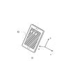
- An example of the portable apparatus 10 which concerns on this embodiment is shown.
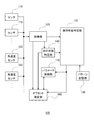
- the structural example of the offset estimation apparatus 100 which concerns on this embodiment is shown.
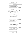
- movement flow of the offset estimation apparatus 100 which concerns on this embodiment is shown.
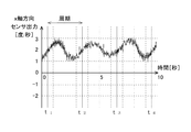
- the 1st example of the output signal of the angular velocity sensor 112 corresponding to the x-axis direction of the portable apparatus 10 which concerns on this embodiment is shown.
- the 1st example of the output signal of the angular velocity sensor 112 corresponding to the y-axis direction of the portable apparatus 10 which concerns on this embodiment is shown.
- the 1st example of the output signal of the angular velocity sensor 112 corresponding to the z-axis direction of the portable apparatus 10 which concerns on this embodiment is shown.
- the 2nd example of the output signal of the angular velocity sensor 112 corresponding to the x-axis direction of the portable apparatus 10 which concerns on this embodiment is shown.
- the 2nd example of the output signal of the angular velocity sensor 112 corresponding to the y-axis direction of the portable apparatus 10 which concerns on this embodiment is shown.
- the 2nd example of the output signal of the angular velocity sensor 112 corresponding to the z-axis direction of the portable apparatus 10 which concerns on this embodiment is shown.
- segmented the specific time interval 410 which concerns on this embodiment into the some area 420 is shown.
- An example is shown in which the offset estimation unit 160 according to the present embodiment determines that a plurality of sections 420 are suitable for offset.
- the offset estimation part 160 which concerns on this embodiment shows an example which judges that the some area 420 is not suitable for an offset.
- An example of a hardware configuration of a computer 1900 functioning as the offset estimation apparatus 100 according to the present embodiment is shown.
- FIG. 1 shows an example of a portable device 10 according to the present embodiment.
- the mobile device 10 includes a plurality of sensors, and detects the movement, the holding state, the position, and the like of the mobile device 10. Further, as an example, the portable device 10 executes calibration or self-diagnosis of each sensor to improve detection sensitivity.
- the portable device 10 includes, for example, a communication function for connecting to an external device and the Internet, a data processing function for executing a program, and the like.
- the mobile device 10 is, for example, a smartphone, a mobile phone, a tablet PC (Personal Computer), a mobile GPS device, or a small PC.
- the mobile device 10 includes a display unit 12.
- the display unit 12 displays, for example, a screen for operating an Internet web page, e-mail, map, document / music / moving image / image data, and the like according to a user instruction.
- the display unit 12 is, for example, a touch panel display to which a user instruction is input, and the user instruction is input to an operation screen of software such as a browser by a touch input from the user.
- the mobile device 10 may receive a user instruction by gesture input.
- the mobile device 10 may be input with a user instruction by an input device such as a keyboard, a mouse, and / or a joystick.
- a plane parallel to the display surface of the display unit 12 is an xy plane and a direction perpendicular to the display surface is a z-axis.
- the display unit 12 has a vertically long rectangular shape. Of the two pairs of opposing sides of the rectangle, the direction along the shorter side (horizontal direction) is the x axis, and the direction along the longer side (vertical direction) is the y axis.
- the direction of swinging the arm and the user's traveling direction are substantially parallel to the xy plane, and the horizontal direction and the z axis Are substantially parallel.
- Such a portable device 10 includes an angular velocity sensor and includes an offset estimation device that estimates an offset of the angular velocity sensor.
- the mobile device 10 includes three angular velocity sensors each having the x-axis, the y-axis, and the z-axis orthogonal to each other in the rotation axis direction.
- the offset estimation device estimates offsets of a plurality of angular velocity sensors, respectively, according to a state where the user holds the mobile device 10.
- the ambient temperature of the angular velocity sensor may change depending on the body temperature of the user.
- the ambient temperature of the angular velocity sensor may change by causing the mobile device 10 to execute a processing operation that places a load on the CPU such as moving image reproduction.
- the offset value may change according to such a change in environment such as temperature. Therefore, the offset estimation apparatus of this embodiment estimates the offset periodically or at a predetermined time or the like, and prevents a decrease in the accuracy of the angular velocity sensor due to a change in the offset over time.
- FIG. 2 shows a configuration example of the offset estimation apparatus 100 according to the present embodiment.
- the offset estimation apparatus 100 determines the holding state of the portable device 10 based on the output of the sensor built in the portable device 10 held by the user, and is built in the portable device 10 according to the determination result of the holding state. Estimate the offset of the angular velocity sensor.
- the offset estimation apparatus 100 includes an acquisition unit 120 that acquires an output signal from a sensor, a holding state determination unit 130, a walking state determination unit 140, a pattern storage unit 150, an offset estimation unit 160, and a parameter control unit 170. Is provided.
- the sensor 110 is mounted on the mobile device 10.
- the sensor 110 includes an angular velocity sensor 112.
- the sensor 110 may include an acceleration sensor and / or a geomagnetic sensor.
- the sensor 110 outputs detection results such as acceleration, angular velocity, and geomagnetism.
- a plurality of angular velocity sensors 112 are mounted according to a plurality of rotation axes of the mobile device 10.
- the angular velocity sensor 112 is, for example, one of an optical gyro sensor that uses the Sagnac effect, a vibration gyro sensor that uses Coriolis force, a fluid gyro sensor, and a mechanical gyro sensor that uses the conservation law of angular momentum, or It is a combination.
- the angular velocity sensor 112 may be a device formed by a MEMS (Micro Electro Mechanical System) technology.
- the acquisition unit 120 is connected to the plurality of sensors 110 and acquires output signals from the sensors 110.
- the acquisition unit 120 acquires an output signal from the sensor 110 according to a holding state such as movement and stationary of the mobile device 10.
- the acquisition unit acquires output signals from a plurality of angular velocity sensors corresponding to a plurality of rotation axes of the mobile device.
- the acquisition unit 120 acquires an output signal corresponding to the movement of the mobile device 10 accompanying the user's walk from the sensor 110.
- the acquisition unit 120 transmits the acquired output signal to the holding state determination unit 130, the walking state determination unit 140, and the offset estimation unit 160.
- the holding state determination unit 130 is connected to the acquisition unit 120 and determines the holding state of the mobile device 10. For example, the holding state determination unit 130 determines the holding state of the mobile device 10 based on the change pattern of the output signal from the sensor 110. In this case, the holding state determination unit 130 determines the holding state of the mobile device 10 by comparing the change pattern of the output signal associated with the user's walking stored in advance with the output signal from the sensor 110.
- the walking state determination unit 140 is connected to the acquisition unit 120 and determines the walking state of the holder of the mobile device 10 according to the output signal of the sensor 110 received from the acquisition unit 120. As an example, the walking state determination unit 140 determines whether or not the user is in a walking state.
- the walking state determination unit 140 is connected to the holding state determination unit 130 and transmits the determination result to the holding state determination unit 130 and the offset estimation unit 160.
- the pattern storage unit 150 stores information indicating the characteristics of the pattern of the output signal for each of the plurality of holding states of the mobile device 10. For example, the pattern storage unit 150 stores a reference feature amount based on an output signal pattern sampled in advance for each of the plurality of holding states. Instead of this or in addition to this, the pattern storage unit 150 may store the pattern of the output signal. Instead of or in addition to this, the pattern storage unit 150 may record the result of analyzing the characteristics of the pattern of the output signal.
- the offset estimation unit 160 is connected to the acquisition unit 120 and the holding state determination unit 130, and estimates the offset of the output signal of the angular velocity sensor 112 according to the output signal of the angular velocity sensor 112 and the determination result of the holding state determination unit 130. To do.
- the offset estimation unit 160 estimates an offset of at least one angular velocity sensor 112 according to the output signal of each angular velocity sensor 112 and the determination result of the holding state determination unit 130. That is, the offset estimation unit 160 determines the angular velocity sensor 112 whose offset should be estimated according to the determination result of the holding state determination unit 130.
- the offset estimation unit 160 is connected to the walking state determination unit 140 and switches whether to estimate the offset of the angular velocity sensor 112 according to the determination result of the walking state determination unit 140. For example, when the user is in a walking state, the offset estimation unit 160 does not estimate the offset of the angular velocity sensor 112.
- the offset estimation unit 160 estimates the offset of the angular velocity sensor 112 using the output signal of the angular velocity sensor 112 under the condition corresponding to the estimation parameter.
- the offset estimation unit 160 sets an estimation parameter for each of the plurality of angular velocity sensors 112.
- the estimation parameter includes, for example, a lower limit and an upper limit threshold of the output fluctuation of the angular velocity sensor 112.
- the estimation parameter may include a specific time interval or data number used for one offset estimation among the output signals of the angular velocity sensor 112.
- the offset estimation unit 160 estimates the offset of the angular velocity sensor 112 on the condition that the output variation of the angular velocity sensor 112 is within a predetermined range at a predetermined time interval.
- the parameter control unit 170 is connected to the holding state determination unit 130 and the offset estimation unit 160, respectively, and controls the estimation parameter of the offset estimation unit 160 according to the determination result of the holding state determination unit 130.
- the parameter control unit 170 changes the estimated parameter of the angular velocity sensor 112 according to the determination result of the holding state determination unit 130 among the plurality of angular velocity sensors 112. For example, the parameter control unit 170 changes the estimated parameter of the angular velocity sensor 112 according to the holding state of the mobile device 10.
- the parameter control unit 170 changes the estimation parameter when the offset estimation unit 160 estimates the offset of the angular velocity sensor 112. For example, the parameter control unit 170 changes the estimation parameter used by the offset estimation unit 160 to estimate the offset.
- the parameter control unit 170 sets the estimation parameter so that the offset estimation is easily performed, so that even if the estimation accuracy is slightly reduced, the estimation can be performed earlier. To. Then, when the first offset estimation is performed, the parameter control unit 170 changes the estimation parameter so that the estimation accuracy is improved over the first estimation in the next estimation.
- the parameter control unit 170 can set the output fluctuation range of the angular velocity sensor 112 to be large at the time of the first estimation, and can set the output fluctuation range to be smaller than the initial estimation at the second time or later. .
- the offset estimation apparatus 100 of the present embodiment described above first determines that the holding state of the mobile device 10 possessed by the user is in one holding state among a plurality of predetermined holding state classifications. For example, as a classification of the holding state of the mobile device 10, the holding state determination unit 130 holds the mobile device 10 in a state where the user holds and operates or visually recognizes the mobile device 10, and makes a call with the mobile device 10 placed on the ear. Holding, holding the mobile device 10 in the hand and shaking the arm, holding in a pocket, and holding in a bag. And the offset estimation apparatus 100 measures the offset of the angular velocity sensor 112 according to the holding state determined by the holding state determination unit 130.
- FIG. 3 shows an operation flow of the offset estimation apparatus 100 according to the present embodiment.
- the offset estimation apparatus 100 estimates the offset of the angular velocity sensor 112 mounted on the mobile device 10 possessed by the user by executing the operation flow shown in FIG.
- the acquisition unit 120 acquires the output signals of the plurality of sensors 110 (S300).
- the plurality of sensors 110 is a total of six sensors, that is, an acceleration sensor that detects acceleration in the orthogonal xyz-axis direction and an angular velocity sensor 112 that detects angular velocity in the xyz-axis direction.
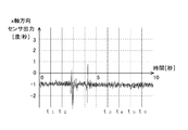
- 4 to 9 show an example of the output signal of such an angular velocity sensor 112.
- FIG. 4 shows a first example of an output signal in the x-axis direction of the angular velocity sensor 112 according to the present embodiment.
- FIGS. 5 and 6 illustrate first examples of output signals of the angular velocity sensor 112 in the y-axis direction and the z-axis direction, respectively.
- 7, 8 and 9 show second examples of output signals in the xyz-axis direction of the angular velocity sensor 112, respectively.
- the acquisition unit 120 acquires the output signals output from the plurality of sensors, and transmits the output signals to the holding state determination unit 130, the walking state determination unit 140, and the offset estimation unit 160.
- the walking state determination unit 140 determines whether or not the user is walking (S310). As an example, the walking state determination unit 140 determines whether or not the user is walking depending on whether or not the output signal from the acceleration sensor fluctuates in a cycle of a predetermined range. When the user walks at approximately the same speed, the user's traveling direction and acceleration in a direction perpendicular to the traveling direction are generated at a substantially constant period. In this case, for example, an acceleration with a period and amplitude corresponding to the user's height, weight, foot length, how to walk, walking speed, etc. is generated, and the acceleration sensor detects the acceleration to detect the user's walking. Outputs vibration pattern according to.
- the walking state determination unit 140 determines whether or not the user is walking based on the characteristics of the pattern of the output signal.
- the walking state determination unit 140 may be connected to the pattern storage unit 150 and compare the pattern feature read from the pattern storage unit 150 with the pattern feature of the output signal.
- the pattern storage unit 150 stores in advance a pattern of an output signal when the user actually walks.
- the walking state determination unit 140 determines that the user is walking by detecting such a change in a substantially constant cycle (S310: Yes)
- the determination result is sent to the holding state determination unit 130 and the offset estimation unit 160.
- the offset estimation apparatus 100 transfers to step S300, and returns to acquisition of the output signal by the acquisition part 120.
- the offset estimation apparatus 100 repeats acquisition of the output signal by the acquisition unit 120 until it detects a state where the user is not walking. In this case, the holding state determination unit 130 and the offset estimation unit 160 do not have to execute the holding state determination operation and the offset estimation operation, respectively.
- the offset estimation device 100 performs the offset estimation operation. Do not migrate to. That is, the offset estimation unit 160 estimates the offset of the angular velocity sensor 112 according to the output of the angular velocity sensor 112 in the determination result of the stationary state of the mobile device 10.
- the offset estimation apparatus 100 proceeds to step S320, and the holding state determination unit 130 The holding state is determined (S320). That is, the holding state determination unit 130 determines the holding state of the mobile device 10 on the condition that it is determined that the user is not walking.
- the holding state determination unit 130 may determine the holding state of the mobile device 10 in parallel with the determination operation of the walking state determination unit 140. In this case, the holding state determination unit 130 sequentially determines a predetermined period of the output signal received from the acquisition unit 120. Then, the holding state determination unit 130 transmits the determination result of the holding state to the offset estimation unit 160 at the timing when the walking state determination unit 140 receives the determination result that determines that the user is not walking.
- the holding state determination unit 130 determines the holding state of the mobile device 10 based on the output signal of the sensor 110 acquired by the acquisition unit 120 and the pattern signal stored in advance by the pattern storage unit 150. For example, the pattern storage unit 150 sets the output signal of the sensor 110 acquired by the acquisition unit 120 corresponding to the user's holding state, or a signal obtained by performing a predetermined calculation on the output signal as the pattern signal. Store in association with each other. Then, the holding state determination unit 130 compares the output signal of the sensor 110 with the pattern signal stored in the pattern storage unit 150, and sets the corresponding holding state as a determination result according to the pattern matching. .
- the holding state determination unit 130 determines the holding state of the mobile device 10 based on which reference feature amount stored in the pattern storage unit 150 corresponds to the feature amount obtained from the output signal. May be. That is, as an example, the pattern storage unit 150 obtains an average value, variance, fluctuation range, and period of the output signal corresponding to the holding state of the mobile device 10 by performing predetermined arithmetic processing such as principal component analysis. Are stored in advance as reference feature values. In this case, the holding state determination unit 130 compares the feature amount obtained by performing a predetermined calculation process on the output signal with the reference feature amount of the stored pattern, and the feature amount is within a predetermined range. In accordance with the coincidence, the corresponding holding state is set as the determination result.
- the holding state determination unit 130 is a relationship between at least two axial components among the axial components when the output signal of the sensor 110 accompanying the user's walking is decomposed into a plurality of axial components.
- the holding state of the mobile device 10 may be determined based on the property.
- the holding state determination is performed.
- the unit 130 may determine the holding state of the mobile device 10 based on the relationship between at least one axial component in the output signal of the first sensor and at least one axial component in the output signal of the second sensor.
- the holding state determination unit 130 determines to which of the plurality of holding states the holding state of the mobile device 10 is classified based on the change patterns of the plurality of axial components in the output signal. As an example, the holding state determination unit 130 determines the holding state of the mobile device 10 according to a waveform pattern of a predetermined period of the output signal.
- the holding state determination unit 130 may determine the holding state of the mobile device 10 based on the output signal of the angular velocity sensor 112 and the pattern signal stored in advance by the pattern storage unit 150.
- the holding state determination unit 130 receives a first example of output signals from the three angular velocity sensors 112 shown in FIGS. 4, 5, and 6, for example, and determines the holding state of the mobile device 10.
- the holding state determination unit 130 receives the second example of the output signals from the three angular velocity sensors 112 shown in FIGS. 7, 8, and 9, and determines the holding state of the mobile device 10. To do.
- FIG. 4 is a first example of an output signal of the angular velocity sensor 112 corresponding to the x-axis direction of the mobile device 10, and is an output signal having periodicity.
- FIG. 5 is a first example of an output signal of the angular velocity sensor 112 corresponding to the y-axis direction of the mobile device 10, and is an output signal in which a noise component increases in a period between 0 seconds and 4 seconds.
- FIG. 6 is a first example of an output signal of the angular velocity sensor 112 corresponding to the z-axis direction of the mobile device 10, and is an output signal having a substantially constant noise component.
- FIG. 7 is a second example of the output signal of the angular velocity sensor 112 corresponding to the x-axis direction of the mobile device 10, and is an output signal in which the noise component increases during a period between 2 seconds and 6 seconds. is there.
- FIG. 8 is a second example of the output signal of the angular velocity sensor 112 corresponding to the y-axis direction of the mobile device 10, and the noise component increases in the period between 0 second to 2 seconds and 7 seconds to 9 seconds.
- FIG. 9 is a second example of an output signal of the angular velocity sensor 112 corresponding to the z-axis direction of the mobile device 10, and is an output signal having periodicity.
- the holding state determination unit 130 indicates that “the x-axis direction has periodicity, the y-axis direction has a sudden noise increase, and the z-axis direction is substantially constant. Extract features such as “with noise component”.
- the holding state determination unit 130 determines whether the noise component is temporarily increased or has a substantially constant noise component, for example, by determining whether the noise component fluctuates within a predetermined range. Extract. Further, the holding state determination unit 130 may extract whether or not it has a periodic characteristic according to a processing result such as Fourier transform. Then, the holding state determination unit 130 matches the extracted feature with the feature pattern stored in the pattern storage unit 150.
- the horizontal direction outputs periodic vibrations reflecting the user's unconscious body movements. Superimposed on the signal.
- the vertical direction y-axis direction
- noise that temporarily increases reflecting the sudden movement of the user's hand or body is superimposed on the output signal.
- the direction (z-axis direction) facing the user's face reflects that the user is looking at the display unit 12, and a substantially constant noise component without blurring is indicated in the output signal.
- the user when the user uses the mobile device 10 as a telephone and makes a call by placing it on his / her ear, the user often holds the mobile device 10 fixed to the ear, and blurring is reduced for each axis.
- the output signal in the x-axis direction and the y-axis direction of the mobile device 10, noise that temporarily increases reflecting sudden movement of the user's hand or body is superimposed on the output signal.
- periodic vibration is reflected in the output signal reflecting the user's unconscious body movement.
- the pattern storage unit 150 associates with the “state in which the user holds the mobile device 10 in his / her hand and looks at the display unit 12”, and “the x-axis direction has periodicity and the y-axis direction is sudden.
- a feature pattern such as “there is an increase in noise and there is a substantially constant noise component in the z-axis direction” is stored in advance.
- the pattern storage unit 150 associates with “a state where the user talks with the mobile device 10 on his / her ear”, “the x-axis direction and the y-axis direction suddenly increase noise, and the z-axis direction indicates Feature patterns such as “with periodicity” are stored in advance.
- the holding state determination unit 130 can determine the holding state of the mobile device 10 by matching the extracted feature with the feature pattern stored in the pattern storage unit 150 in advance.
- the holding state determination unit 130 transmits the determined holding state to the parameter control unit 170 and the offset estimation unit 160.
- the parameter control unit 170 changes the estimated parameter of the angular velocity sensor 112 according to the holding state of the mobile device 10 (S330). As described above, the output signal from the angular velocity sensor 112 that accompanies the holding state of the user's portable device 10 is significantly different for each holding state. Therefore, for example, the parameter control unit 170 changes the estimation parameter of the offset estimation unit 160 to an estimation parameter corresponding to the holding state for each axis.
- the parameter control unit 170 responds to the x-axis direction of the mobile device 10 in response to receiving the determination result “the user is holding the mobile device 10 in his hand and looking at the display unit 12”.
- a specific time interval used for one offset estimation of the angular velocity sensor 112 is made to substantially coincide with the cycle of the output signal of the angular velocity sensor 112.
- the parameter control unit 170 determines that the output signal of the angular velocity sensor 112 corresponding to the x-axis direction has periodicity based on the determination result of the holding state, and therefore changes the parameter to the estimated parameter at substantially the same time interval as the period. be able to.
- the parameter control unit 170 compares a specific time interval used for one offset estimation of the angular velocity sensor 112 corresponding to the y-axis direction of the mobile device 10 with a time interval of the angular velocity sensor 112 corresponding to the z-axis direction. Shorten it. Since the parameter control unit 170 finds that the output signal of the angular velocity sensor 112 corresponding to the y-axis direction has suddenly increased noise from the determination result of the holding state, the time interval used for offset estimation is shortened.
- the estimation parameter can be changed as follows.
- the parameter control unit 170 also compares a specific time interval used for one offset estimation of the angular velocity sensor 112 corresponding to the z-axis direction of the mobile device 10 with a time interval of the angular velocity sensor 112 corresponding to the y-axis direction. Make it longer.
- the parameter control unit 170 finds that there is substantially constant noise in the output signal of the angular velocity sensor 112 corresponding to the z-axis direction from the determination result of the holding state, so that the time interval used for offset estimation is lengthened. It is possible to change the estimation parameter.
- the parameter control unit 170 may control the estimation parameter according to the previous and current determination results of the holding state determination unit 130. For example, when the offset estimation unit 160 continuously determines the same holding state, the parameter control unit 170 keeps the estimation parameter unchanged without changing the estimation parameter, and the determination result of the holding state determination unit 130 changes. In case, the estimation parameter is changed.
- the offset estimation unit 160 estimates an offset according to the output signal of the angular velocity sensor 112 and the determination result of the holding state determination unit 130 (S340).
- the offset estimation unit 160 for example, in response to receiving the determination result of “the user is holding the mobile device 10 in his hand and looking at the display unit 12”, the angular velocity sensor 112 corresponding to the z-axis direction. Estimate the offset.
- the offset estimation unit 160 uses the time interval used for the offset estimation changed by the parameter control unit 170, and uses the average value of the output signals of the angular velocity sensor 112 acquired in the time interval as the offset estimation result. Output. More specifically, when the output signal of the angular velocity sensor 112 corresponding to the z-axis direction in FIG. 6 is obtained, the offset estimation unit 160 outputs at time intervals t1 to t2 and / or t2 to t3,. Output the average value of the signal. In the example of FIG. 6, the angular velocity sensor 112 estimates the offset at intervals of about 3 seconds, and the estimation result is about 1 [degrees / second].
- the offset estimation unit 160 may estimate the offset when the output signal of the angular velocity sensor 112 is within the range of the lower limit and the upper limit threshold of the output fluctuation determined by the parameter control unit 170. For example, the offset estimation unit 160 calculates an average value, a maximum value, and a minimum value for each time interval used for offset estimation, and the difference between the average value and the maximum value and the minimum value is an upper limit threshold value and a lower limit threshold value, respectively. Depending on being in the range, the average value is output as an offset.
- the parameter control unit 170 sets the threshold corresponding to the output fluctuation when the angular velocity sensor 112 outputs a substantially constant noise component as the estimation parameter in the step S330.
- the parameter control unit 170 may measure the output fluctuation when the angular velocity sensor 112 outputs a substantially constant noise component in advance, and set a threshold according to the measurement result.
- the angular velocity sensor A threshold value calculated from 112 design specifications or the like may be set.
- the offset estimation unit 160 can estimate the offset by selecting the angular velocity sensor 112 that outputs a substantially constant noise component according to the holding state. That is, the offset estimation unit 160 can estimate an offset in which the influence of noise fluctuation caused by the user's movement or the like is reduced even if the mobile device 10 is not fixed in a stationary state.
- the offset estimation unit 160 receives the determination result of “the user is holding the mobile device 10 in his / her hand and looking at the display unit 12” and the angular velocity sensor 112 corresponding to the x-axis direction. An offset may be estimated. In this case, the offset estimation unit 160 outputs an average value of the output signals of the angular velocity sensor 112 acquired at a time interval substantially coincident with the cycle of the output signal of the angular velocity sensor 112 as an offset estimation result.
- the offset estimation unit 160 is time intervals t1 to t2, t2 to t3, and / or t3 to t4, Outputs the average value of the output signal at.
- the angular velocity sensor 112 estimates the offset at intervals of about 3 seconds, and the estimation result is about 2 [degrees / second].
- the offset estimation unit 160 may estimate the offset when the output signal of the angular velocity sensor 112 is within the range of the lower limit and the upper limit threshold of the output fluctuation determined by the parameter control unit 170.
- the parameter control unit 170 may set a threshold corresponding to an output signal having periodic fluctuations due to unintentional movement of the user as an estimated parameter in step S330.
- the parameter control unit 170 increases the threshold range in the x-axis direction by the amount of periodic fluctuations compared to the threshold range defined in the z-axis direction, and sudden fluctuations. Make it smaller than the range.
- the parameter control unit 170 may measure in advance periodic output fluctuations according to the user's movement of the angular velocity sensor 112 and sudden output fluctuations, and set a threshold value according to the measurement results.
- the offset estimation unit 160 selects the angular velocity sensor 112 that outputs a signal having periodic fluctuations according to the holding state, and uses the cycle to calculate the offset. Can be estimated. Accordingly, the offset estimation unit 160 can estimate the offset by reducing the periodic fluctuation caused by the user's movement or the like.
- the offset estimation unit 160 receives the determination result of “the user is holding the portable device 10 in his / her hand and looking at the display unit 12” and the angular velocity sensor 112 corresponding to the y-axis direction. An offset may be estimated. In this case, the offset estimation unit 160 estimates the offset at a short time interval as compared to the case where the angular velocity sensor 112 outputs a substantially constant noise component according to the estimation parameter.
- the offset estimation unit 160 estimates the offset when the output signal of the angular velocity sensor 112 is within the range of the lower limit and the upper limit threshold of the output fluctuation determined by the parameter control unit 170.
- the parameter control unit 170 sets a threshold corresponding to the sudden output fluctuation caused by the user's movement by the angular velocity sensor 112 as an estimated parameter in step S330.
- the parameter control unit 170 makes the range of the threshold value in the y-axis direction smaller than the range of sudden fluctuation.
- the parameter control unit 170 may measure sudden output fluctuation according to the user's movement of the angular velocity sensor 112 in advance, and set a threshold value according to the measurement result.
- the offset estimation unit 160 estimates the offset in the time interval from 0 to t1 because the sudden output fluctuation is large. Does not execute. And the offset estimation part 160 outputs the average value of an output signal in time intervals, such as t1 to t2, t2 to t3, .... In the case of the example of FIG. 5, the angular velocity sensor 112 estimates the offset at intervals of about 1 second, and the estimation result is about 2 [degrees / second].
- the offset estimation unit 160 selects the angular velocity sensor 112 that is likely to cause sudden output fluctuations depending on the holding state even if the user holds the portable device 10, and the sudden output fluctuations occur.
- the offset can be estimated using the output signal in the case of not doing so.
- the offset estimation unit 160 shortens the time interval used for estimation, it can be prevented that the estimation of the offset cannot be performed or the execution time becomes long due to the sudden output fluctuation. . Accordingly, the offset estimation unit 160 can estimate the offset by reducing sudden fluctuations caused by the user's movement or the like.
- the offset estimation apparatus 100 can estimate the offset of the angular velocity sensor 112 according to the first example of the output signal of the angular velocity sensor 112. Similarly, the offset estimation apparatus 100 can also estimate the offset of the angular velocity sensor 112 according to the second example of the output signal of the angular velocity sensor 112. That is, the offset estimation apparatus 100 can estimate the offset of the angular velocity sensor 112 according to the holding state of the portable device 10 even when the user holds the portable device 10.
- the parameter control unit 170 changes the estimated parameter (S350). That is, the parameter control unit 170 controls the estimation parameter when the offset of the angular velocity sensor 112 is estimated by the offset estimation unit 160. For example, immediately after the offset estimation unit 160 estimates the offset, the parameter control unit 170 increases the time interval used for the estimation. Further, the parameter control unit 170 narrows the ranges of the lower limit and the upper limit threshold of the output fluctuation used for estimation. That is, the parameter control unit 170 makes the conditions under which the offset estimation unit 160 executes the offset estimation after the next time strict.
- the offset estimation unit 160 executes the next offset estimation when the output of the angular velocity sensor 112 is more stable and less fluctuated than the offset estimation that has already been performed, and a longer time can be used for the estimation time.
- the offset estimation unit 160 once estimates the offset, if the output fluctuation of the angular velocity sensor 112 changes in an unstable direction, the execution of the offset estimation from the next time is stopped, and the angular velocity sensor 112
- the offset can be estimated only under the condition that the output fluctuation changes in a more stable direction and the offset can be estimated accurately.
- the parameter control unit 170 does not execute the next offset estimation after the offset estimation unit 160 estimates the offset, and if the time longer than the predetermined time has elapsed, Conditions for performing the estimation may be relaxed. Since the offset of the angular velocity sensor 112 changes with time, even if the offset is estimated once with accuracy, the offset may vary from the actual offset value as time passes.
- the parameter control unit 170 relaxes the condition for executing the offset estimation when a predetermined time has elapsed from the offset estimation, and causes the offset estimation unit 160 to execute the offset estimation. Also in this case, the parameter control unit 170 may tighten the conditions for executing the offset estimation from the next time after the offset estimation unit 160 executes the offset estimation. Thereby, even if the offset of the angular velocity sensor 112 changes with time, the offset estimation unit 160 can continue the estimation of the offset and prevent a decrease in accuracy.
- the parameter control unit 170 may determine an evaluation value corresponding to the estimation parameter, and lower the evaluation value as time elapses.
- the parameter control unit 170 may determine an evaluation value according to the determination result of the holding state determination unit 130.
- the parameter control unit 170 determines whether the holding state determination unit 130 determines that the user is holding the mobile device 10 in his hand and is viewing the display unit 12 in the z-axis direction and the x-axis direction. And the evaluation value of the estimation parameter for estimating the offset of the angular velocity sensor 112 corresponding to each direction is decreased in the order of the y-axis direction. That is, the parameter control unit 170 increases the evaluation value for a state in which the fluctuation of the output signal of the angular velocity sensor 112 is more stable.
- the parameter control unit 170 determines, for example, the evaluation value of the estimated parameter in the z-axis direction in response to the determination that the holding state determination unit 130 is “a state where the user talks with the mobile device 10 placed on the ear”.
- the evaluation value is larger than the evaluation values in the x-axis direction and the y-axis direction.
- the parameter control unit 170 determines the evaluation value in the z-axis direction when the holding state determination unit 130 determines that “the user is holding the mobile device 10 in his hand and looking at the display unit 12”. It is made substantially equal to the evaluation value in the axial direction.
- the parameter control unit 170 determines the evaluation values in the x-axis direction and the y-axis direction in the y-axis direction when it is determined that “the user is holding the mobile device 10 in his hand and looking at the display unit 12” Is made approximately equal to the evaluation value of.
- the parameter control unit 170 includes, in the characteristics of the signal component of the angular velocity sensor 112, “when it has a substantially constant noise component”, “when it has a periodic noise component”, and “a sudden increase in noise”.
- the evaluation value is made smaller in the order of “when having”.
- the parameter control unit 170 decreases each evaluation value by a predetermined number for each predetermined time in a period in which the offset estimation unit 160 does not perform the offset estimation. Further, when the offset estimation unit 160 does not perform the offset estimation, the parameter control unit 170 does not update the evaluation value corresponding to the holding state even if the holding state determination unit 130 receives the determination result of the holding state.
- the offset estimation unit 160 estimates the offset on the condition that the parameter control unit 170 increases the evaluation value corresponding to the estimation parameter. For example, when the offset estimation unit 160 estimates an offset in response to the determination that the holding state determination unit 130 is “a state in which the user holds the mobile device 10 in his / her hand and looks at the display unit 12”, the parameter control The unit 170 determines the evaluation value of the estimation parameter according to the determination result of the holding state. Next, during a period in which the offset estimation unit 160 stops estimating the offset, the parameter control unit 170 decreases the evaluation value of each estimation parameter by a predetermined number every predetermined time.
- the holding state determination unit 130 determines that “the user holds the mobile device 10 in his hand and looks at the display unit 12”, the previous determination result and Although the evaluation result is the same, the estimated value of the estimated parameter decreases with time. Therefore, when the evaluated value is updated, the parameter control unit 170 increases the evaluated value. Therefore, the offset estimation unit 160 performs offset estimation, and the parameter control unit 170 updates the evaluation value.
- the determination result is different from the previous determination result.
- the evaluation value of the estimated parameter decreases with the passage of time, whether or not the evaluation value is increased even if the parameter control unit 170 updates the evaluation value indicates whether or not the evaluation value is increased. It depends on the determined holding state. That is, the offset estimation unit 160 performs the offset estimation when the evaluation value of the previously estimated offset estimation parameter is lower than the current evaluation value with the passage of time.
- the offset estimation unit 160 estimates the offset of the angular velocity sensor 112
- the offset estimation unit 160 depends on the evaluation value of the estimation parameter. It is possible to determine the decrease in reliability. Therefore, when the offset estimation unit 160 can execute offset estimation with higher reliability, the offset estimation unit 160 can estimate the offset and prevent the reliability of the estimation result from being lowered even if the offset fluctuates.
- the user changes the holding state of the mobile device 10 to make the angular velocity sensor 112 in a stable output signal state unstable, and the time has passed so that the reliability has decreased from the previous offset estimation. If not, the offset estimation unit 160 does not perform offset estimation because the evaluation value of the estimation parameter does not increase. In other words, the offset estimation unit 160 can determine that the offset estimation has low reliability from the evaluation value of the estimation parameter, holds the high reliability estimation result, and is updated with the low reliability estimation result. Can be prevented.
- the offset estimation unit 160 may compare evaluation values for each rotation axis of the mobile device 10 and determine whether or not to perform offset estimation for each rotation axis.
- the portable device 10 is controlled while controlling estimation parameters such as the time used for estimation, the lower limit of output fluctuation, and the upper limit threshold according to the holding state of the portable device 10. It is possible to estimate the offset of the angular velocity sensor 112 mounted on the vehicle 10. Thereby, the offset estimation apparatus 100 can reduce the influence of the output fluctuation of the angular velocity sensor 112 and estimate a more accurate offset in a short time even when the mobile device 10 is not stationary. Therefore, even if the offset of the angular velocity sensor 112 changes with time, the offset estimation apparatus 100 can periodically estimate the offset and prevent a decrease in measurement accuracy of the angular velocity sensor 112.
- the offset estimation apparatus 100 has been described as an example in which the user does not shift to the offset estimation operation when the user is walking.
- the offset estimation apparatus 100 may shift to an offset estimation operation if the output fluctuation of the angular velocity sensor 112 is a fluctuation within a predetermined range. For example, when the user walks slowly, the offset estimation operation may be executed during the user's walking motion as long as the walking motion does not affect the offset estimation of the offset estimation apparatus 100.
- the walking state determination unit 140 determines that the user is not in the walking state even if the user's walking state is detected. Thereby, the offset estimation apparatus 100 can shift to the offset estimation operation, and can increase the opportunity of the offset estimation operation to prevent the measurement accuracy of the angular velocity sensor from being lowered.
- the offset estimation unit 160 calculates the offset at a specific time interval in which the output signal of the angular velocity sensor 112 is within the range of the lower limit and the upper limit threshold of the output fluctuation determined by the parameter control unit 170.
- An example of estimation has been described.
- the offset estimation unit 160 may divide a specific time interval into a plurality of sections, and estimate the offset based on the data of the output signal of the angular velocity sensor 112 in the plurality of sections.
- the offset estimation unit 160 divides a specific time interval into a plurality of sections, calculates the maximum value and the minimum value of the data of the output signal of the angular velocity sensor 112 in the plurality of sections, and Among them, data in a section where the difference between the maximum value and the minimum value in each section is smaller than a predetermined threshold is set as a candidate for offset estimation.
- the offset estimation unit 160 calculates the variance value of the data of the output signal of the angular velocity sensor in a plurality of sections, and the variance value in each section of the plurality of sections is calculated. Data in a section smaller than a predetermined threshold may be used as a candidate for offset estimation.
- the offset estimation unit 160 calculates an offset from the data that is a candidate for offset estimation. May be estimated.
- the parameter control unit 170 may change the predetermined number according to the determination result of the holding state determination unit 130.
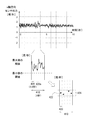
- the offset estimation unit 160 outputs, as an offset, an average value of data that is set as a candidate for offset estimation in a specific time interval. The operation of the offset estimation unit 160 will be described with reference to FIGS. 10 and 11.
- FIG. 10 shows an example in which a specific time interval 410 according to the present embodiment is divided into a plurality of sections 420.
- the offset estimation unit 160 divides the time interval 410 used for offset estimation into a plurality of minute time intervals 420, and performs a predetermined calculation process on the output signal of the angular velocity sensor 112 acquired in each interval 420. Execute.
- the offset estimation unit 160 calculates an average value, a maximum value, and a minimum value in each section 420, and the section 420 is offset in accordance with the difference between the maximum value and the minimum value being within the threshold range. It is determined that the section is suitable for estimation. Further, if the number of sections 420 suitable for offset in the time interval 410 is equal to or greater than a predetermined number, the offset estimation unit 160 calculates the average value of the output signals of the angular velocity sensor 112 in the section suitable for offset estimation. , May be output as an offset. That is, the offset estimation unit 160 may discard data that is not suitable for offset estimation without using it for offset estimation.
- the offset estimation unit 160 obtains a dispersion value of the output signal of the angular velocity sensor 112 acquired in the section 420, and whether the dispersion value is within a predetermined threshold range. Depending on whether or not, it may be determined whether or not the section 420 is a section suitable for offset estimation. Here, in each of the sections 420 divided from the time interval 410, the influence of noise fluctuations caused by the user's movement or the like may be included. Therefore, the offset estimation unit 160 degrades the offset estimation accuracy by not using the output signal of the angular velocity sensor 112 in the section including the influence of such noise fluctuations without using it for the offset estimation. Can be prevented.
- the parameter control unit 170 may change the threshold value of the number of sections 420 suitable for offset in the time interval 410 according to the determination result of the holding state determination unit 130.
- the offset estimation of the output signal of the x-axis of the angular velocity sensor 112 will be specifically described as an example.
- the angular velocity sensor 112 updates the output signal at a sampling interval of 100 Hz, and the offset estimation unit 160 divides the time interval 410 used for the offset estimation into 1 second, and divides the time interval 410 into five sections 420 to estimate the offset.
- An example of executing is described.
- the sampling data of the time interval 410 is 100 pieces.
- the data of the angular velocity sensor per section 420 is for the time interval of 200 ms, that is, 20 pieces.
- the offset estimation unit 160 calculates the maximum value and the minimum value from the 20 data of the angular velocity sensor 112, and if the difference is within a predetermined threshold range, the 20 data is suitable for the offset estimation. It is determined that the data is correct. Moreover, if the difference between the maximum value and the minimum value is outside the range of the threshold value, the offset estimation unit 160 determines that 20 pieces of data are unsuitable for offset estimation and does not use it for offset estimation.
- the offset estimation unit 160 determines whether each of the five sections 420 is a section suitable for offset estimation.
- FIG. 10 shows an example in which four sections 420 are determined to be sections suitable for offset estimation. That is, FIG. 10 is an example in which the offset estimation unit 160 determines that the section 420a is not suitable for offset estimation because the maximum value of the output data of the angular velocity sensor 112 exceeds a predetermined threshold.
- the offset estimation unit 160 further sets a threshold value 3 for determining whether or not the number of sections 420 is equal to or greater than a predetermined number.
- the offset estimation unit 160 determines that the four sections 420 are suitable for the offset and exceeds the number threshold, so that the output data of the angular velocity sensor 112 in the four sections 420, that is, An average value of output data of 80 angular velocity sensors 112 for a total of 800 msec is calculated as an offset.
- the offset estimation unit 160 determines whether each section 420 is suitable for offset estimation based on the maximum value and the minimum value of the output data of the angular velocity sensor 112 in each section 420 will be described. did. Instead of or in addition to this, the offset estimation unit 160 obtains an average value of the output data of the angular velocity sensor 112 for each section 420, and whether each section 420 is suitable for offset estimation based on the average value. It may be judged.
- FIG. 11 shows an example in which the offset estimation unit 160 according to the present embodiment determines that a plurality of sections 420 are suitable for offset.
- FIG. 12 illustrates an example in which the offset estimation unit 160 according to the present embodiment determines that the plurality of sections 420 are not suitable for offset.
- the offset estimation unit 160 calculates the maximum value and the minimum value from the four average values 422 calculated for each of the four sections 420, and the difference between the maximum value and the minimum value is within a predetermined threshold 424 range. It is determined whether or not the four sections 420 are suitable for offset estimation.
- the difference between the maximum value and the minimum value of the four average values 422 corresponding to the four sections 420 is within the range of the predetermined threshold value 424.
- the output data of the angular velocity sensor 112 in the two sections 420 is used for offset estimation.
- the difference between the maximum value and the minimum value of the four average values 422 is outside the range of the predetermined threshold value 424. Therefore, the offset estimation unit 160 determines that the four sections 420 are offset estimated. Therefore, the output data of the angular velocity sensor 112 in the four sections 420 is not used for offset estimation.
- the offset estimation unit 160 determines whether or not the data is suitable for the offset estimation based on the maximum value, the minimum value, and the average value of the output data of the angular velocity sensor 112. It is possible to prevent the offset estimation accuracy from deteriorating.
- the offset estimation unit 160 may determine the current offset based on the past offset and the offset estimated at the present time. For example, if there is an offset estimated in the past rather than one offset, the offset estimation unit 160 determines that the absolute value of the difference between the average value of the offset estimated in the past and the one offset is greater than a predetermined threshold value. If it is smaller, output one offset. In addition, the offset estimation unit does not output one offset when the absolute value of the difference between the average value of the previously estimated offset and the one offset is larger than a predetermined threshold value. In this case, the offset estimation unit 160 may continue to use the offset estimated one before the estimation of one offset.
- the offset estimation unit 160 determines whether to output one offset based on the variance of the offset estimated in the past and the variance of the one offset. You may judge.
- the variance of one offset uses, as an example, the variance of output data of the angular velocity sensor 112 used for estimating the one offset.
- the offset estimating unit 160 does not adopt the offset as that caused by some noise and / or malfunction. .
- the offset estimation unit 160 can remove the influence of fluctuation due to noise or the like and prevent the offset estimation accuracy from deteriorating.
- FIG. 13 shows an example of a hardware configuration of a computer 1900 that functions as the offset estimation apparatus 100 according to the present embodiment.
- a computer 1900 according to the present embodiment is mounted, for example, inside the mobile device 10. Instead, the computer 1900 may be provided outside the mobile device 10, receive a sensor output from the mobile device 10, and transmit an offset estimation result or the like to the mobile device 10. In this case, the computer 1900 transmits and receives wirelessly to and from the mobile device 10 as an example.
- the computer 1900 includes a CPU peripheral unit including a CPU 2000, a RAM 2020, a graphic controller 2075, and a display device 2080 that are connected to each other by a host controller 2082, and a communication interface 2030 that is connected to the host controller 2082 by an input / output controller 2084.
- the host controller 2082 connects the RAM 2020 to the CPU 2000 and the graphic controller 2075 that access the RAM 2020 at a high transfer rate.
- the CPU 2000 operates based on programs stored in the ROM 2010 and the RAM 2020 and controls each unit.
- the graphic controller 2075 acquires image data generated by the CPU 2000 or the like on a frame buffer provided in the RAM 2020 and displays it on the display device 2080.
- the graphic controller 2075 may include a frame buffer for storing image data generated by the CPU 2000 or the like.
- the input / output controller 2084 connects the host controller 2082 to the communication interface 2030, the storage unit 2040, and the input / output unit 2060 which are relatively high-speed input / output devices.
- the communication interface 2030 communicates with other devices via a network.
- Storage unit 2040 stores programs and data used by CPU 2000 in computer 1900.
- the storage unit 2040 is a nonvolatile memory, such as a flash memory or a hard disk.
- the input / output unit 2060 is connected to the connector 2095, transmits / receives a program or data to / from the outside, and provides the storage unit 2040 via the RAM 2020.
- the input / output unit 2060 may transmit / receive to / from the outside with a standardized connector and communication method.
- the input / output unit 2060 is a standard such as USB, IEEE 1394, HDMI (registered trademark), or Thunderbolt (registered trademark). May be used.
- the input / output unit 2060 may transmit and receive with the outside using a wireless communication standard such as Bluetooth (registered trademark).
- the ROM 2010, the card slot 2050, and the relatively low-speed input / output device of the input / output chip 2070 are connected to the input / output controller 2084.
- the ROM 2010 stores a boot program that the computer 1900 executes at startup and / or a program that depends on the hardware of the computer 1900.
- the card slot 2050 reads a program or data from the memory card 2090 and provides it to the storage unit 2040 via the RAM 2020.
- the input / output chip 2070 connects the card slot 2050 to the input / output controller 2084 and, for example, various input / output devices via the parallel port, serial port, keyboard port, mouse port, etc. You may connect to.
- the program provided to the storage unit 2040 via the RAM 2020 is provided by the user via the input / output unit 2060 or stored in a recording medium such as the memory card 2090.
- the program is read from the recording medium, installed in the storage unit 2040 in the computer 1900 via the RAM 2020, and executed by the CPU 2000.
- the program is installed in the computer 1900, and causes the computer 1900 to function as the acquisition unit 120, the holding state determination unit 130, the walking state determination unit 140, the pattern storage unit 150, the offset estimation unit 160, and the parameter control unit 170.
- the information processing described in the program is read into the computer 1900, whereby the acquisition unit 120, the holding state determination unit 130, and the walking state determination are specific means in which the software and the various hardware resources described above cooperate.
- the specific offset estimation apparatus 100 according to a use purpose is constructed
- the CPU 2000 executes a communication program loaded on the RAM 2020 and executes a communication interface based on the processing content described in the communication program.
- a communication process is instructed to 2030.
- the communication interface 2030 receives transmission data stored in a transmission buffer area or the like provided in a storage device or the like connected via the RAM 2020, the storage unit 2040, the memory card 2090, or the input / output unit 2060 under the control of the CPU 2000.
- the data is read and transmitted to the network, or the received data received from the network is written into a reception buffer area or the like provided on the storage device.
- the communication interface 2030 may transfer transmission / reception data to / from the storage device by the DMA (Direct Memory Access) method. Instead, the CPU 2000 transfers the storage device or the communication interface 2030 as the transfer source.
- the transmission / reception data may be transferred by reading the data from the data and writing the data to the communication interface 2030 or the storage device of the transfer destination.
- the CPU 2000 uses the RAM 2020 to transfer all or necessary portions from among files or databases stored in the storage unit 2040, the memory card 2090, or a storage device connected via the input / output unit 2060 by DMA transfer or the like. And various processes are performed on the data on the RAM 2020. Then, CPU 2000 writes the processed data back to the storage device by DMA transfer or the like.
- the RAM 2020 can be regarded as temporarily holding the contents of the storage device, in the present embodiment, the RAM 2020 and the storage device are collectively referred to as a memory, a storage unit, or a storage device.
- Various types of information such as various programs, data, tables, and databases in the present embodiment are stored on such a storage device and are subjected to information processing.
- the CPU 2000 can also store a part of the RAM 2020 in the cache memory and perform reading and writing on the cache memory. Even in such a form, the cache memory bears a part of the function of the RAM 2020. Therefore, in the present embodiment, the cache memory is also included in the RAM 2020, the memory, and / or the storage device unless otherwise indicated. To do.
- the CPU 2000 performs various operations, such as various operations, information processing, condition determination, information search / replacement, etc., described in the present embodiment, specified for the data read from the RAM 2020 by the instruction sequence of the program. Is written back to the RAM 2020. For example, when performing the condition determination, the CPU 2000 determines whether the various variables shown in the present embodiment satisfy the conditions such as large, small, above, below, equal, etc., compared to other variables or constants. When the condition is satisfied (or not satisfied), the program branches to a different instruction sequence or calls a subroutine.
- the CPU 2000 can search for information stored in a file or database in the storage device. For example, in the case where a plurality of entries in which the attribute value of the second attribute is associated with the attribute value of the first attribute are stored in the storage device, the CPU 2000 displays the plurality of entries stored in the storage device. The entry that matches the condition in which the attribute value of the first attribute is specified is retrieved, and the attribute value of the second attribute that is stored in the entry is read, thereby associating with the first attribute that satisfies the predetermined condition The attribute value of the specified second attribute can be obtained.
- the programs or modules shown above may be stored in an external recording medium.
- an optical recording medium such as a DVD, Blu-ray (registered trademark) or CD
- a magneto-optical recording medium such as an MO
- a tape medium such as an IC card, or the like
- a semiconductor memory such as an IC card, or the like
- a storage device such as a hard disk or a RAM provided in a server system connected to a dedicated communication network or the Internet may be used as a recording medium, and the program may be provided to the computer 1900 via the network.
Landscapes
- Engineering & Computer Science (AREA)
- Physics & Mathematics (AREA)
- General Physics & Mathematics (AREA)
- Computer Networks & Wireless Communication (AREA)
- Signal Processing (AREA)
- Radar, Positioning & Navigation (AREA)
- Manufacturing & Machinery (AREA)
- Remote Sensing (AREA)
- Environmental & Geological Engineering (AREA)
- Human Computer Interaction (AREA)
- Gyroscopes (AREA)
- Navigation (AREA)
- Telephone Function (AREA)
Abstract
Description
[特許文献1] 特開平9-152338号公報
[特許文献2] 特開2004-212382号公報
Claims (26)
- 携帯機器に搭載される角速度センサからの出力信号を取得する取得部と、
前記携帯機器の保持状態を判定する保持状態判定部と、
前記保持状態判定部の判定結果に応じて、前記角速度センサの出力信号のオフセットを推定するオフセット推定部と
を備えるオフセット推定装置。 - 前記保持状態判定部の判定結果に応じて、前記オフセット推定部の推定パラメータを制御するパラメータ制御部を備える請求項1に記載のオフセット推定装置。
- 前記取得部は、前記携帯機器の前記角速度センサから複数の回転軸に応じた出力信号を取得し、
前記オフセット推定部は、前記複数の回転軸に応じた出力信号と前記保持状態判定部の判定結果とに応じて、前記角速度センサのオフセットを推定する
請求項2に記載のオフセット推定装置。 - 前記オフセット推定部は、前記推定パラメータに応じた条件下にある前記角速度センサの出力信号を用いて当該角速度センサのオフセットを推定する請求項3に記載のオフセット推定装置。
- 前記パラメータ制御部は、前記角速度センサのうち、前記保持状態判定部の判定結果に応じた角速度センサの前記推定パラメータを変更する請求項2から4のいずれか一項に記載のオフセット推定装置。
- 前記パラメータ制御部は、前記オフセット推定部による前記角速度センサのオフセットの推定が実行された場合に、前記推定パラメータを変更する請求項2から5のいずれか一項に記載のオフセット推定装置。
- 前記パラメータ制御部は、前記保持状態判定部の判定結果が変化した場合に、前記推定パラメータを変更する請求項2から6のいずれか一項に記載のオフセット推定装置。
- 前記オフセット推定部は、前記携帯機器の静止状態の判定結果における前記角速度センサの出力に応じて、前記角速度センサのオフセットを推定する請求項2から7のいずれか一項に記載のオフセット推定装置。
- 前記携帯機器の保持者の歩行状態を判定する歩行状態判定部を更に備え、
前記オフセット推定部は、前記歩行状態判定部の判定結果に応じて、前記角速度センサのオフセットを推定するか否かを切り替える請求項2から8のいずれか一項に記載のオフセット推定装置。 - 前記推定パラメータは、前記角速度センサの出力変動の下限および上限の閾値を含む請求項2から9のいずれか一項に記載のオフセット推定装置。
- 前記推定パラメータは、前記角速度センサの出力信号のうち、1回のオフセット推定に用いる特定の時間間隔またはデータ数を含む請求項2から10のいずれか一項に記載のオフセット推定装置。
- 前記オフセット推定部は、
前記特定の時間間隔を複数の区間に分割し、
前記複数の区間における前記角速度センサの出力信号のデータの最大値および最小値をそれぞれ算出し、
前記複数の区間のうち、それぞれの区間における前記最大値と前記最小値との差が予め定められた第1の閾値よりも小さい前記区間のデータを、オフセット推定の候補とする請求項11に記載のオフセット推定装置。 - 前記オフセット推定部は、さらに、
前記複数の区間における前記角速度センサの出力信号のデータの分散値をそれぞれ算出し、
前記複数の区間のうち、それぞれの区間における前記分散値が予め定められた第2の閾値よりも小さい前記区間のデータを、オフセット推定の候補とする請求項12に記載のオフセット推定装置。 - 前記オフセット推定部は、
前記特定の時間間隔を複数の区間に分割し、
前記複数の区間における前記角速度センサの出力信号のデータの分散値をそれぞれ算出し、
前記複数の区間のうち、それぞれの区間における前記分散値が予め定められた第2の閾値よりも小さい前記区間のデータを、オフセット推定の候補とする請求項11に記載のオフセット推定装置。 - 前記オフセット推定部は、
前記特定の時間間隔のうち前記オフセット推定の候補とされたデータを有する区間の数が予め定められた数以上である場合に、前記オフセット推定の候補となるデータから前記オフセットを推定する請求項12から14のいずれか一項に記載のオフセット推定装置。 - 前記オフセット推定部は、前記特定の時間間隔のうち前記オフセット推定の候補とされたデータの平均値を前記オフセットとして出力する請求項15に記載のオフセット推定装置。
- 前記パラメータ制御部は、
前記保持状態判定部の判定結果に応じて、前記予め定められた数を変更する請求項15または16に記載のオフセット推定装置。 - 前記オフセット推定部は、さらに、
一のオフセットよりも過去に推定したオフセットが存在する場合、前記過去に推定したオフセットの平均値と、前記一のオフセットとの差の絶対値が予め定められた第3の閾値よりも小さい場合に、前記一のオフセットを出力する請求項15から17のいずれか一項に記載のオフセット推定装置。 - 前記オフセット推定部は、
前記過去に推定したオフセットの前記平均値と前記一のオフセットとの差の絶対値が予め定められた第3の閾値よりも大きい場合に、前記一のオフセットを出力しない請求項18に記載のオフセット推定装置。 - 前記オフセット推定部は、
一のオフセットよりも過去に推定したオフセットが存在する場合、前記過去に推定したオフセットの分散と前記一のオフセットの分散とに基づき、前記一のオフセットを出力するか否かを判断する請求項15から17のいずれか一項に記載のオフセット推定装置。 - 前記パラメータ制御部は、前記推定パラメータに対応する評価値を定め、前記評価値を時間経過に応じて下げていく請求項2から20のいずれか一項に記載のオフセット推定装置。
- 前記パラメータ制御部は、前記保持状態判定部の判定結果に応じて前記評価値を定める請求項21に記載のオフセット推定装置。
- 前記オフセット推定部は、前記推定パラメータに対応する前記評価値を前記パラメータ制御部が増加させることを条件に、前記角速度センサのオフセットを推定する請求項21または22に記載のオフセット推定装置。
- 携帯機器に搭載される角速度センサからの出力信号を取得する取得部と、
推定パラメータに応じた条件下にある前記角速度センサの出力信号に応じて、前記角速度センサのオフセットを推定するオフセット推定部と
前記オフセット推定部による前記角速度センサのオフセットが推定された場合に、前記推定パラメータを制御するパラメータ制御部と
を備えるオフセット推定装置。 - 携帯機器に搭載される角速度センサのオフセットを推定する方法であって、
前記携帯機器の保持状態を判定する段階と、
前記携帯機器の保持状態の判定結果に応じて、前記角速度センサのオフセットを推定する段階と
を備える方法。 - コンピュータを、請求項1から24のいずれか一項に記載のオフセット推定装置として機能させるプログラム。
Priority Applications (4)
| Application Number | Priority Date | Filing Date | Title |
|---|---|---|---|
| JP2015516894A JP5974171B2 (ja) | 2013-05-15 | 2014-04-18 | オフセット推定装置、方法、およびプログラム |
| CN201480027051.1A CN105324638B (zh) | 2013-05-15 | 2014-04-18 | 偏移估计装置、方法以及程序 |
| EP14797672.4A EP2998702A4 (en) | 2013-05-15 | 2014-04-18 | Offset estimation device, method, and program |
| US14/924,983 US20160047840A1 (en) | 2013-05-15 | 2015-10-28 | Offset estimation apparatus, offset estimation method, and computer readable medium |
Applications Claiming Priority (2)
| Application Number | Priority Date | Filing Date | Title |
|---|---|---|---|
| JP2013-103274 | 2013-05-15 | ||
| JP2013103274 | 2013-05-15 |
Related Child Applications (1)
| Application Number | Title | Priority Date | Filing Date |
|---|---|---|---|
| US14/924,983 Continuation US20160047840A1 (en) | 2013-05-15 | 2015-10-28 | Offset estimation apparatus, offset estimation method, and computer readable medium |
Publications (1)
| Publication Number | Publication Date |
|---|---|
| WO2014185009A1 true WO2014185009A1 (ja) | 2014-11-20 |
Family
ID=51898002
Family Applications (1)
| Application Number | Title | Priority Date | Filing Date |
|---|---|---|---|
| PCT/JP2014/002208 Ceased WO2014185009A1 (ja) | 2013-05-15 | 2014-04-18 | オフセット推定装置、方法、およびプログラム |
Country Status (5)
| Country | Link |
|---|---|
| US (1) | US20160047840A1 (ja) |
| EP (1) | EP2998702A4 (ja) |
| JP (1) | JP5974171B2 (ja) |
| CN (1) | CN105324638B (ja) |
| WO (1) | WO2014185009A1 (ja) |
Cited By (4)
| Publication number | Priority date | Publication date | Assignee | Title |
|---|---|---|---|---|
| JP2018159569A (ja) * | 2017-03-22 | 2018-10-11 | カシオ計算機株式会社 | 姿勢算出装置、姿勢計測システム、及び姿勢算出方法 |
| JP2018166268A (ja) * | 2017-03-28 | 2018-10-25 | パナソニックIpマネジメント株式会社 | 制御プログラム及び携帯機器 |
| JP2020139883A (ja) * | 2019-02-28 | 2020-09-03 | ラピスセミコンダクタ株式会社 | オフセット算出装置、オフセット補正装置及びオフセット算出方法 |
| CN112867908A (zh) * | 2018-10-18 | 2021-05-28 | 罗伯特·博世有限公司 | 用于转速传感器的转速传感器信号的偏移校准的方法、系统、计算机程序 |
Families Citing this family (5)
| Publication number | Priority date | Publication date | Assignee | Title |
|---|---|---|---|---|
| KR102606286B1 (ko) * | 2016-01-07 | 2023-11-24 | 삼성전자주식회사 | 전자 장치 및 전자 장치를 이용한 소음 제어 방법 |
| CN111142687B (zh) * | 2018-11-02 | 2022-04-12 | 华为技术有限公司 | 一种行走检测方法及装置 |
| CN109405852A (zh) * | 2018-12-17 | 2019-03-01 | 北京无线电测量研究所 | 一种三轴模拟量陀螺标定系统及方法 |
| CN113341308B (zh) * | 2021-04-19 | 2023-04-18 | 云南电网有限责任公司临沧供电局 | 一种隔离开关动作特性的判断方法和系统 |
| CN116226609B (zh) * | 2023-01-31 | 2026-01-30 | 苏州华兴源创科技股份有限公司 | 一种信号偏移的判断方法、装置、计算机设备 |
Citations (5)
| Publication number | Priority date | Publication date | Assignee | Title |
|---|---|---|---|---|
| JPH07324941A (ja) * | 1994-06-02 | 1995-12-12 | Matsushita Electric Ind Co Ltd | オフセットドリフト補正装置 |
| JPH09152338A (ja) | 1995-12-01 | 1997-06-10 | Fujitsu Ten Ltd | ジャイロ装置 |
| JPH09318648A (ja) * | 1996-05-28 | 1997-12-12 | Toyota Motor Corp | 車両用角速度検出装置 |
| JP2004212382A (ja) | 2002-12-31 | 2004-07-29 | Lg Electron Inc | ロボット掃除機の回転位置誤差補正方法 |
| JP2008003002A (ja) * | 2006-06-23 | 2008-01-10 | Asahi Kasei Electronics Co Ltd | 角速度計測装置 |
Family Cites Families (7)
| Publication number | Priority date | Publication date | Assignee | Title |
|---|---|---|---|---|
| JPH0694734A (ja) * | 1992-03-23 | 1994-04-08 | Taya Eng Kk | 角速度検出センサーにおけるドリフトキャンセル方式およびその装置 |
| JP2007040765A (ja) * | 2005-08-01 | 2007-02-15 | Toyota Motor Corp | 角速度センサの零点補正装置 |
| EP2260763A1 (en) * | 2008-03-31 | 2010-12-15 | Sharp Kabushiki Kaisha | Body motion measuring device, mobile telephone, method for controlling the body motion measuring device, body motion measuring device control program, and computer-readable recording medium having the program recorded therein |
| JP4780168B2 (ja) * | 2008-09-29 | 2011-09-28 | 日本ビクター株式会社 | 角速度センサ補正装置および角速度センサ補正方法 |
| JP5520071B2 (ja) * | 2010-02-05 | 2014-06-11 | キヤノン株式会社 | 像振れ補正装置および像振れ補正装置を備えた光学機器、撮像装置、像振れ補正装置の制御方法 |
| JP5757742B2 (ja) * | 2010-03-25 | 2015-07-29 | セイコーインスツル株式会社 | 電子機器、歩数計、およびプログラム |
| WO2012111793A1 (ja) * | 2011-02-18 | 2012-08-23 | Necカシオモバイルコミュニケーションズ株式会社 | ジャイロセンサ付き携帯電子機器、そのジャイロセンサ補正方法及びプログラム |
-
2014
- 2014-04-18 CN CN201480027051.1A patent/CN105324638B/zh not_active Expired - Fee Related
- 2014-04-18 WO PCT/JP2014/002208 patent/WO2014185009A1/ja not_active Ceased
- 2014-04-18 JP JP2015516894A patent/JP5974171B2/ja not_active Expired - Fee Related
- 2014-04-18 EP EP14797672.4A patent/EP2998702A4/en not_active Withdrawn
-
2015
- 2015-10-28 US US14/924,983 patent/US20160047840A1/en not_active Abandoned
Patent Citations (5)
| Publication number | Priority date | Publication date | Assignee | Title |
|---|---|---|---|---|
| JPH07324941A (ja) * | 1994-06-02 | 1995-12-12 | Matsushita Electric Ind Co Ltd | オフセットドリフト補正装置 |
| JPH09152338A (ja) | 1995-12-01 | 1997-06-10 | Fujitsu Ten Ltd | ジャイロ装置 |
| JPH09318648A (ja) * | 1996-05-28 | 1997-12-12 | Toyota Motor Corp | 車両用角速度検出装置 |
| JP2004212382A (ja) | 2002-12-31 | 2004-07-29 | Lg Electron Inc | ロボット掃除機の回転位置誤差補正方法 |
| JP2008003002A (ja) * | 2006-06-23 | 2008-01-10 | Asahi Kasei Electronics Co Ltd | 角速度計測装置 |
Non-Patent Citations (1)
| Title |
|---|
| See also references of EP2998702A4 |
Cited By (7)
| Publication number | Priority date | Publication date | Assignee | Title |
|---|---|---|---|---|
| JP2018159569A (ja) * | 2017-03-22 | 2018-10-11 | カシオ計算機株式会社 | 姿勢算出装置、姿勢計測システム、及び姿勢算出方法 |
| JP2018166268A (ja) * | 2017-03-28 | 2018-10-25 | パナソニックIpマネジメント株式会社 | 制御プログラム及び携帯機器 |
| CN112867908A (zh) * | 2018-10-18 | 2021-05-28 | 罗伯特·博世有限公司 | 用于转速传感器的转速传感器信号的偏移校准的方法、系统、计算机程序 |
| JP2020139883A (ja) * | 2019-02-28 | 2020-09-03 | ラピスセミコンダクタ株式会社 | オフセット算出装置、オフセット補正装置及びオフセット算出方法 |
| CN111623798A (zh) * | 2019-02-28 | 2020-09-04 | 拉碧斯半导体株式会社 | 偏移计算装置、偏移修正装置以及偏移计算方法 |
| JP7239349B2 (ja) | 2019-02-28 | 2023-03-14 | ラピスセミコンダクタ株式会社 | オフセット算出装置、オフセット補正装置及びオフセット算出方法 |
| CN111623798B (zh) * | 2019-02-28 | 2024-07-05 | 拉碧斯半导体株式会社 | 偏移计算装置、偏移修正装置以及偏移计算方法 |
Also Published As
| Publication number | Publication date |
|---|---|
| US20160047840A1 (en) | 2016-02-18 |
| JPWO2014185009A1 (ja) | 2017-02-23 |
| JP5974171B2 (ja) | 2016-08-23 |
| EP2998702A4 (en) | 2017-01-11 |
| EP2998702A1 (en) | 2016-03-23 |
| CN105324638B (zh) | 2018-09-11 |
| CN105324638A (zh) | 2016-02-10 |
Similar Documents
| Publication | Publication Date | Title |
|---|---|---|
| JP5974171B2 (ja) | オフセット推定装置、方法、およびプログラム | |
| EP2773920A2 (en) | System and method for improving orientation data | |
| JP2014224715A (ja) | 進行方向推定装置、方法、およびプログラム | |
| US10247558B2 (en) | Travel direction determination apparatus, map matching apparatus, travel direction determination method, and computer readable medium | |
| JP6033418B2 (ja) | オフセット推定装置、オフセット推定方法、およびプログラム | |
| JP6175127B2 (ja) | 保持状態判定装置およびプログラム | |
| JP6073455B2 (ja) | 保持状態変化検知装置、保持状態変化検知方法、およびプログラム | |
| JP6250708B2 (ja) | 進行方向情報出力装置、マップマッチング装置、進行方向情報出力方法、およびプログラム | |
| JP6697567B2 (ja) | 歩数計数装置、歩数計数方法、およびプログラム | |
| JP2017518488A (ja) | ソフト制約及びペナルティ機能を使用した慣性センサの初期化 | |
| CN104995584B (zh) | 计算磁航向 | |
| US20150362315A1 (en) | Systems and methods for determining position information using environmental sensing | |
| CN121917799A (zh) | 用于测量速度的方法、装置、设备和程序产品 | |
| CN120176718A (zh) | 传感器的标定方法、装置、计算机设备及存储介质 | |
| HK1236610B (zh) | 对地球重力的估计的生成 |
Legal Events
| Date | Code | Title | Description |
|---|---|---|---|
| WWE | Wipo information: entry into national phase |
Ref document number: 201480027051.1 Country of ref document: CN |
|
| 121 | Ep: the epo has been informed by wipo that ep was designated in this application |
Ref document number: 14797672 Country of ref document: EP Kind code of ref document: A1 |
|
| ENP | Entry into the national phase |
Ref document number: 2015516894 Country of ref document: JP Kind code of ref document: A |
|
| WWE | Wipo information: entry into national phase |
Ref document number: 2014797672 Country of ref document: EP |
|
| NENP | Non-entry into the national phase |
Ref country code: DE |