WO2014185019A1 - Dispositif de protection de porte-bagages de toit - Google Patents
Dispositif de protection de porte-bagages de toit Download PDFInfo
- Publication number
- WO2014185019A1 WO2014185019A1 PCT/JP2014/002323 JP2014002323W WO2014185019A1 WO 2014185019 A1 WO2014185019 A1 WO 2014185019A1 JP 2014002323 W JP2014002323 W JP 2014002323W WO 2014185019 A1 WO2014185019 A1 WO 2014185019A1
- Authority
- WO
- WIPO (PCT)
- Prior art keywords
- cushion
- crossbar
- cover body
- sections
- protector
- Prior art date
- Legal status (The legal status is an assumption and is not a legal conclusion. Google has not performed a legal analysis and makes no representation as to the accuracy of the status listed.)
- Ceased
Links
Images







Classifications
-
- B—PERFORMING OPERATIONS; TRANSPORTING
- B60—VEHICLES IN GENERAL
- B60R—VEHICLES, VEHICLE FITTINGS, OR VEHICLE PARTS, NOT OTHERWISE PROVIDED FOR
- B60R9/00—Supplementary fittings on vehicle exterior for carrying loads, e.g. luggage, sports gear or the like
- B60R9/04—Carriers associated with vehicle roof
- B60R9/048—Carriers characterised by article-gripping, -covering,-retaining, or -locking means
-
- B—PERFORMING OPERATIONS; TRANSPORTING
- B60—VEHICLES IN GENERAL
- B60R—VEHICLES, VEHICLE FITTINGS, OR VEHICLE PARTS, NOT OTHERWISE PROVIDED FOR
- B60R9/00—Supplementary fittings on vehicle exterior for carrying loads, e.g. luggage, sports gear or the like
- B60R9/04—Carriers associated with vehicle roof
- B60R9/052—Carriers comprising elongate members extending only transversely of vehicle
Definitions
- the present invention relates to an improvement of a protector used by being attached to a cross bar of an automobile roof carrier, and in particular, can be easily attached to a cross bar having various cross-sectional shapes to obtain a good protection effect.
- the present invention relates to a protector for a roof carrier.
- Japanese Utility Model Laid-Open No. 6-23835 is known as a roof carrier protector.
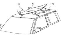
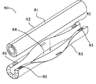
- this roof carrier protector 80 has a protector 80 mounted on a crossbar 120 of a roof carrier of an automobile, As shown in FIG. 11, a single slit-shaped notch 81 is formed over the entire length in the longitudinal direction as the protector 80 that is used by being attached to the crossbar 120 as described above.
- a cylindrical cushion 82 is inserted into an opening 84 of the cover body 83 into a cover body 83 that is sewn at both ends in the longitudinal direction and sewn in a bag shape.
- a hook-and-loop fastener 85 is provided in the vicinity of both end portions of the cover, and the entire cover is covered with a cover 83 as shown in FIG.
- the structure for fixing the cushion 82 and the cover member 83 in the surface fastener 85 is disclosed.
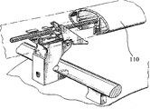
- the crossbar has a cross-sectional shape that is wider than the vertical width as shown in FIG. 110 has increased, and it is difficult to press-fit the cushion 82 having the structure disclosed in the Japanese Utility Model Laid-Open No. 6-23835 into the crossbar 110 having a wider width than the vertical width.
- the roof carrier protector 80 cannot be mounted on the crossbar 110 having a width that is wider than the vertical width.
- the roof of the present invention can be easily mounted not only on a crossbar having a circular cross-sectional shape but also on a crossbar having a wide width with respect to the vertical width, and a good protection effect can be obtained.
- the purpose is to provide a protector for carriers.
- the protector for a roof carrier includes a substantially cylindrical cushion housed inside a bag-shaped cover body, and is used for a roof carrier that is used by mounting the cushion together with the cover body on a cross bar of an automobile roof carrier.
- the cover body has a mounting maintenance means for maintaining a state in which the roof carrier cushion is mounted on the cross bar, and the cushion has a separation portion in a longitudinal direction, and is formed by the separation portion.
- the pair of end portions arranged at the end portions of the cover body, the cushion has a plurality of sections between the pair of end sections, and the adjacent sections are relative to each other according to the shape of the crossbar. It has the means to move to.
- the means in which adjacent sections move relatively according to the shape of the crossbar includes a configuration in which a plurality of sections are separated by a cutting portion formed in a longitudinal direction between a pair of end portions of the cushion. And good.
- a portion in which the adjacent sections move relatively according to the shape of the crossbar is separated into a plurality of sections by a kerf formed on the inner surface in the longitudinal direction between the pair of end portions of the cushion. And a thin-walled portion connected between the tip of the kerf and the outer peripheral surface.
- a portion in which adjacent sections move relatively according to the shape of the crossbar is separated into a plurality of sections by a concave groove formed in a longitudinal direction between a pair of ends of the cushion; A thin-walled portion connected in the concave groove.
- the present invention can be easily mounted not only on a crossbar having a circular cross-sectional shape as described above, but also on a crossbar having a width that is wider than the vertical width, thereby obtaining an effective protection effect. It has an effect that can be.
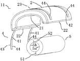
- FIG. 1 is a perspective view of a roof carrier protector 1 according to a first embodiment of the present invention before assembling.
- the cover body 2 has an elongated bag shape and is accommodated over almost the entire interior of the cover body 2.
- a cushion 3 formed of a flexible material such as polyurethane, which is configured to be arranged around a cross bar of a roof carrier of an automobile together with the cover body 2, and the cover body 2 and the cushion 3 are arranged around the cross bar.
- From the hook-and-loop fastener 44 disposed and fixed to the fixing portion 42 and the free end 43 of the belt 41 and the cover body 2 of the belt 41 so as to be wound around the outer periphery of the cover body 2 and fixed to the crossbar. It has the mounting maintenance means 4 which becomes.
- the cover body 2 is sewn in a bag shape, and has a cushion insertion opening 21 formed of a vertically long groove-like hole on the inner surface thereof.
- the cushion 3 housed in the cover body 2 from the cushion insertion opening 21 is formed in a cylindrical shape having an outer diameter of about 70 mm and an inner diameter of about 34 mm (wall thickness: 18 mm), and is U-shaped by cutting portions 31 and 32 formed in the longitudinal direction.
- Each of the cushions 3 has a pair of one end surfaces 33 formed by the cutting part 31 disposed on the end part 22 of the cover body 2, respectively, The pair of other end surfaces 34 formed by the portion 32 are stored so that the other end surfaces 34 face each other at a substantially central position 23 in the cover body 2.
- the cushion 3 has two sections 3 a and 3 b formed by the cutting portion 32.
- the pair of other end faces 34 are attached to the crossbar 100 in a state where they face each other substantially parallel at the substantially central position 23 in the cover body 2, and the roof carrier protector 1 is detached from the crossbar 100 by the attachment maintaining means 4. Is fixed so that it does not easily disengage.
- the roof carrier protector 1 according to the present invention when the roof carrier protector 1 according to the present invention is attached to the crossbar 110 having a width wider than the vertical width, the other pair of the two sections 3a and 3b of the cushion 3 is used.
- the crossbar 110 In a state in which the distance between the end faces 34 is relatively moved in the direction in which the lower interval is wider than the upper direction according to the width and shape of the crossbar 110, and the attachment maintaining means 4
- the roof carrier protector 1 is fixed from the cross bar 110 so as not to be easily detached.
- the cushion 3 is separated into two sections.
- the cushion 3 may be divided into three or more sections (not shown), for example, approximately three.
- the cushion 3 formed in a U shape from the beginning may be used in combination.
- the attachment maintaining means in the present embodiment is composed of a fixing portion 42 between the belt 41 and the cover body 2 of the belt 41 and a hook-and-loop fastener 44 fixed to the free end 43, but the attachment maintaining means 4 in the present invention. Is not limited to this embodiment, and other existing structures may be used.
- FIG. 4 is a perspective view of the roof carrier protector 11 according to the second embodiment of the present invention before assembly.
- the cover body 2 and the attachment maintaining means 4 are implemented. Since the configuration is the same as that of Example 1, description thereof is omitted.
- the cover body 2 is formed of a flexible material such as polyurethane which is accommodated over almost the entire interior of the cover body 2 and can be disposed around the crossbar of the roof carrier of the automobile together with the cover body 2.
- the cushion 5 has a cylindrical shape with an outer diameter of about 70 mm and an inner diameter of about 34 mm (wall thickness: 18 mm), and has one end face 53 formed by a single separated portion by a cutting portion 51 formed in the longitudinal direction.
- the cushion inner surface is separated halfway by a cut groove 52 formed in the longitudinal direction on the inner surface of the cushion 5 at a position symmetrical to the separation portion with respect to the shaft, and a pair of other end surfaces 54 and the cushion
- the non-separation part 55 is formed in the outer peripheral part rather than the 5 cut grooves 52.
- the cushion 5 is separated into two sections 5 a and 5 b through the non-separating portion 55, and the two sections 5 a and 5 b have a pair of other end surfaces 54 that are based on the non-separating portion 55. As described above, it is configured to be relatively expandable according to the width of the crossbar. If the thickness of the non-separating portion 55 is too thin, the non-separating portion 55 is likely to be cut by an external force or the like, and if it is too thick, the function as the spread base when moving relative to the width of the crossbar is impaired.
- the non-separating portion 55 is preferably about 2 mm to 6 mm in thickness (1/9 to 1/3 of the wall thickness).
- the roof carrier protector 11 of the present invention when the roof carrier protector 11 of the present invention is mounted on a conventional square crossbar 100, the cushion 5 is divided into two sections 5a partially separated by the kerf 52, The pair of other end faces 54 of 5b are mounted on the crossbar 100 in a state of facing each other, and the roof carrier protector 11 is fixed from the crossbar 100 so as not to be easily detached by the mounting maintaining means 4.
- the cushion 5 is adjacent to the non-separating portion 55 as a base point.
- the two sections 5a and 5b to be mounted are mounted on the crossbar 110 in a state of being relatively moved in the direction in which the gap is widened below the kerf 52 according to the width and shape of the crossbar 110, and the mounting is maintained.
- the roof carrier protector 11 is fixed by the means 4 so as not to be easily detached from the cross bar 110.
- the cushion 5 is separated into two sections 5a and 5b by one kerf 52.
- the cushion 5 is separated into three or more sections, for example, by two kerfs. May be configured. (Not shown)
- the cushion 5 in the manufacturing method of the cushion 5, a plurality of sections are formed in a state where they are connected by a thin portion, respectively, and in use, the cushion sections adjacent to the thin portion are configured so as to be close to each other in a kerf shape. Also good.
- the attachment maintaining means 4 in the present invention is not limited to this embodiment, and other existing structures may be used.
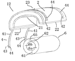
- FIG. 7 is a perspective view of the roof carrier protector 12 according to the third embodiment of the present invention before assembly.
- the cover body 2 and the attachment maintaining means 4 are implemented. Since the configuration is the same as that of Example 1, description thereof is omitted.
- the cover body 2 is formed of a flexible material such as polyurethane which is accommodated over almost the entire interior of the cover body 2 and can be disposed around the crossbar of the roof carrier of the automobile together with the cover body 2.
- the cushion 6 has a cylindrical shape having an outer diameter of about 70 mm and an inner diameter of about 34 mm (wall thickness: 18 mm), and has one end face 63 formed by a separation portion formed by a cutting portion 61 formed in the longitudinal direction.
- the cushion inner surface is separated halfway by a concave groove 62 formed in the longitudinal direction on the inner surface of the cushion 6 at a position symmetrical to the separation portion with respect to the central axis, whereby the pair of other end surfaces 64 and the cushion 6 are separated.
- a thin portion 65 is formed on the outer peripheral portion of the concave groove 62.
- the cushion 6 is separated into two sections 6a and 6b through a thin section 65 formed by the concave groove 62, and the two sections 6a and 6b have a pair of other end faces 64 that are separated from each other.
- the thin portion 65 As a base point, it is configured to be relatively expandable according to the width of the crossbar. In addition, if the thickness of the thin portion 65 is too thin, the thin portion 65 is likely to be damaged by an external force or the like, and if it is too thick, the function as the spread base when moving relative to the width of the crossbar is impaired.
- the thin portion 65 is desirably about 2 mm to 6 mm (1/9 to 1/3 of the wall thickness).
- the concave groove 62 is not limited to the configuration of the present embodiment, and may be provided on the outer surface of the cushion 6 or may be provided on both the inner surface and the outer surface of the cushion.
- the roof carrier protector 12 of the present invention when the roof carrier protector 12 of the present invention is mounted on a conventional square crossbar 100, the cushion 6 is divided into two sections 6a partially separated by the concave groove 62, The pair of other end faces 64 of 6b are mounted on the crossbar 100 in a state of facing each other, and the roof carrier protector 12 is fixed by the mounting maintaining means 4 so as not to be easily detached from the crossbar 100.
- the cushion 6 is adjacent to the thin portion 65 as a base point.
- the two sections 6a and 6b are attached to the crossbar 110 in a state where they are relatively moved in the direction in which the gap is widely opened below the concave groove 62 in accordance with the width and shape of the crossbar 110, and the attachment maintaining means. 4, the roof carrier protector 12 is fixed so as not to be easily detached from the cross bar 110.
- the cushion 6 is separated into two sections by one concave groove.
- the cushion 6 is separated into three sections by two concave grooves, and is divided into three or more sections. Also good. (Not shown)
- the cushion 6 a plurality of sections are formed in a state where they are connected by thin portions, respectively, and in the state of use, the cushion sections adjacent to the thin portions are configured so as to be close to a concave groove shape. Also good.
- the attachment maintaining means in the present invention is not limited to this embodiment, and other existing structures may be used.
Landscapes
- Engineering & Computer Science (AREA)
- Mechanical Engineering (AREA)
- Fittings On The Vehicle Exterior For Carrying Loads, And Devices For Holding Or Mounting Articles (AREA)
Abstract
Le problème décrit par la présente invention est de fournir un dispositif de protection de porte-bagages de toit qui peut être facilement monté sur les barres transversales d'une variété de formes en coupe transversale et qui peut produire un effet de protection favorable. La solution selon l'invention porte sur un coussin pratiquement cylindrique qui est rangé à l'intérieur d'un couvercle en forme de sac, le couvercle comportant un moyen de maintien de montage pour conserver un état dans lequel un coussin pour un porte-bagages de toit a été monté sur la barre transversale. Le coussin présente des sections de découpe formées d'une surface de découpe formée dans le sens longitudinal et une configuration qui est formée dans le sens longitudinal entre les sections transversales et est apte à un mouvement conformément à la forme de la barre transversale.
Applications Claiming Priority (2)
| Application Number | Priority Date | Filing Date | Title |
|---|---|---|---|
| JP2013103457A JP6095476B2 (ja) | 2013-05-15 | 2013-05-15 | ルーフキャリア用プロテクター |
| JP2013-103457 | 2013-05-15 |
Publications (1)
| Publication Number | Publication Date |
|---|---|
| WO2014185019A1 true WO2014185019A1 (fr) | 2014-11-20 |
Family
ID=51898012
Family Applications (1)
| Application Number | Title | Priority Date | Filing Date |
|---|---|---|---|
| PCT/JP2014/002323 Ceased WO2014185019A1 (fr) | 2013-05-15 | 2014-04-24 | Dispositif de protection de porte-bagages de toit |
Country Status (2)
| Country | Link |
|---|---|
| JP (1) | JP6095476B2 (fr) |
| WO (1) | WO2014185019A1 (fr) |
Cited By (2)
| Publication number | Priority date | Publication date | Assignee | Title |
|---|---|---|---|---|
| EP3031669A1 (fr) * | 2014-12-12 | 2016-06-15 | Thule Sweden AB | Kit de galerie de toit et bande de charge pour barre de support de charge |
| WO2016194492A1 (fr) * | 2015-05-29 | 2016-12-08 | 株式会社カーメイト | Dispositif de protection de galerie de toit |
Citations (4)
| Publication number | Priority date | Publication date | Assignee | Title |
|---|---|---|---|---|
| JPH0435936U (fr) * | 1990-07-24 | 1992-03-25 | ||
| JPH0623835U (ja) * | 1992-08-31 | 1994-03-29 | 有限会社岡本製作所 | ルーフキャリア用クッション |
| US5947354A (en) * | 1997-02-06 | 1999-09-07 | Bradley Stewart Fraser | Carrier for vehicle roofs |
| JP2001047945A (ja) * | 1999-08-03 | 2001-02-20 | J Create:Kk | ルーフバーエアロアタッチメント |
-
2013
- 2013-05-15 JP JP2013103457A patent/JP6095476B2/ja active Active
-
2014
- 2014-04-24 WO PCT/JP2014/002323 patent/WO2014185019A1/fr not_active Ceased
Patent Citations (4)
| Publication number | Priority date | Publication date | Assignee | Title |
|---|---|---|---|---|
| JPH0435936U (fr) * | 1990-07-24 | 1992-03-25 | ||
| JPH0623835U (ja) * | 1992-08-31 | 1994-03-29 | 有限会社岡本製作所 | ルーフキャリア用クッション |
| US5947354A (en) * | 1997-02-06 | 1999-09-07 | Bradley Stewart Fraser | Carrier for vehicle roofs |
| JP2001047945A (ja) * | 1999-08-03 | 2001-02-20 | J Create:Kk | ルーフバーエアロアタッチメント |
Cited By (3)
| Publication number | Priority date | Publication date | Assignee | Title |
|---|---|---|---|---|
| EP3031669A1 (fr) * | 2014-12-12 | 2016-06-15 | Thule Sweden AB | Kit de galerie de toit et bande de charge pour barre de support de charge |
| US10391946B2 (en) | 2014-12-12 | 2019-08-27 | Thule Sweden Ab | Roof rack kit and a load strip for a load carrying bar |
| WO2016194492A1 (fr) * | 2015-05-29 | 2016-12-08 | 株式会社カーメイト | Dispositif de protection de galerie de toit |
Also Published As
| Publication number | Publication date |
|---|---|
| JP2014223838A (ja) | 2014-12-04 |
| JP6095476B2 (ja) | 2017-03-15 |
Similar Documents
| Publication | Publication Date | Title |
|---|---|---|
| USD1045720S1 (en) | Vehicle windshield | |
| USD876326S1 (en) | All-terrain vehicle tire | |
| US9770074B2 (en) | Cap structure having a plurality of breach hole features and zipper head assembly structure using the same | |
| JP5668617B2 (ja) | 経路維持部材付コルゲートチューブ及びワイヤーハーネス | |
| USD844495S1 (en) | Vehicle grille | |
| US20140338158A1 (en) | Cap structure having an inner surface concave feature and zipper head assembly structure using the same | |
| USD941223S1 (en) | Automobile wheel center cap | |
| JP6095476B2 (ja) | ルーフキャリア用プロテクター | |
| USD941735S1 (en) | Automobile wheel center cap | |
| USD941222S1 (en) | Automobile wheel center cap | |
| JP5556321B2 (ja) | 車両用シートのヘッドレストサポート取付構造 | |
| ES2349621T1 (es) | Dispositivo limitador de desplazamiento lateral para estabilizadores. | |
| JP2013018336A (ja) | ステアリングホイール構造 | |
| JP2014230414A (ja) | プロテクタ | |
| JP7234893B2 (ja) | クッションシート及びワイヤハーネス | |
| JP3922643B2 (ja) | 作業帽 | |
| JP6574686B2 (ja) | コルゲートチューブ保持具、及び、保持具付きコルゲートチューブ | |
| JP4681633B2 (ja) | 顔面保護マスク | |
| JP6705161B2 (ja) | タングプレート保持具 | |
| USD539713S1 (en) | Windshield visor | |
| JP2010124593A (ja) | 電線の保護材 | |
| JP3633899B2 (ja) | 締付けバンド | |
| JP3221637U (ja) | 筆巻ホルダ | |
| WO2014203710A1 (fr) | Tapis comprenant un faisceau de conducteurs, et procédé de fabrication d'un tapis comprenant un faisceau de conducteurs | |
| KR20200133381A (ko) | 벨트 통과구 |
Legal Events
| Date | Code | Title | Description |
|---|---|---|---|
| 121 | Ep: the epo has been informed by wipo that ep was designated in this application |
Ref document number: 14797827 Country of ref document: EP Kind code of ref document: A1 |
|
| NENP | Non-entry into the national phase |
Ref country code: DE |
|
| 122 | Ep: pct application non-entry in european phase |
Ref document number: 14797827 Country of ref document: EP Kind code of ref document: A1 |