WO2014188501A1 - Cellule secondaire à électrolyte non aqueux - Google Patents
Cellule secondaire à électrolyte non aqueux Download PDFInfo
- Publication number
- WO2014188501A1 WO2014188501A1 PCT/JP2013/063994 JP2013063994W WO2014188501A1 WO 2014188501 A1 WO2014188501 A1 WO 2014188501A1 JP 2013063994 W JP2013063994 W JP 2013063994W WO 2014188501 A1 WO2014188501 A1 WO 2014188501A1
- Authority
- WO
- WIPO (PCT)
- Prior art keywords
- positive electrode
- negative electrode
- electrode current
- current collector
- sheet
- Prior art date
- Legal status (The legal status is an assumption and is not a legal conclusion. Google has not performed a legal analysis and makes no representation as to the accuracy of the status listed.)
- Ceased
Links
Images









Classifications
-
- H—ELECTRICITY
- H01—ELECTRIC ELEMENTS
- H01M—PROCESSES OR MEANS, e.g. BATTERIES, FOR THE DIRECT CONVERSION OF CHEMICAL ENERGY INTO ELECTRICAL ENERGY
- H01M10/00—Secondary cells; Manufacture thereof
- H01M10/05—Accumulators with non-aqueous electrolyte
- H01M10/058—Construction or manufacture
- H01M10/0587—Construction or manufacture of accumulators having only wound construction elements, i.e. wound positive electrodes, wound negative electrodes and wound separators
-
- H—ELECTRICITY
- H01—ELECTRIC ELEMENTS
- H01M—PROCESSES OR MEANS, e.g. BATTERIES, FOR THE DIRECT CONVERSION OF CHEMICAL ENERGY INTO ELECTRICAL ENERGY
- H01M50/00—Constructional details or processes of manufacture of the non-active parts of electrochemical cells other than fuel cells, e.g. hybrid cells
- H01M50/50—Current conducting connections for cells or batteries
- H01M50/531—Electrode connections inside a battery casing
- H01M50/536—Electrode connections inside a battery casing characterised by the method of fixing the leads to the electrodes, e.g. by welding
-
- Y—GENERAL TAGGING OF NEW TECHNOLOGICAL DEVELOPMENTS; GENERAL TAGGING OF CROSS-SECTIONAL TECHNOLOGIES SPANNING OVER SEVERAL SECTIONS OF THE IPC; TECHNICAL SUBJECTS COVERED BY FORMER USPC CROSS-REFERENCE ART COLLECTIONS [XRACs] AND DIGESTS
- Y02—TECHNOLOGIES OR APPLICATIONS FOR MITIGATION OR ADAPTATION AGAINST CLIMATE CHANGE
- Y02E—REDUCTION OF GREENHOUSE GAS [GHG] EMISSIONS, RELATED TO ENERGY GENERATION, TRANSMISSION OR DISTRIBUTION
- Y02E60/00—Enabling technologies; Technologies with a potential or indirect contribution to GHG emissions mitigation
- Y02E60/10—Energy storage using batteries
-
- Y—GENERAL TAGGING OF NEW TECHNOLOGICAL DEVELOPMENTS; GENERAL TAGGING OF CROSS-SECTIONAL TECHNOLOGIES SPANNING OVER SEVERAL SECTIONS OF THE IPC; TECHNICAL SUBJECTS COVERED BY FORMER USPC CROSS-REFERENCE ART COLLECTIONS [XRACs] AND DIGESTS
- Y02—TECHNOLOGIES OR APPLICATIONS FOR MITIGATION OR ADAPTATION AGAINST CLIMATE CHANGE
- Y02P—CLIMATE CHANGE MITIGATION TECHNOLOGIES IN THE PRODUCTION OR PROCESSING OF GOODS
- Y02P70/00—Climate change mitigation technologies in the production process for final industrial or consumer products
- Y02P70/50—Manufacturing or production processes characterised by the final manufactured product
Definitions
- the present invention relates to a non-aqueous electrolyte secondary battery having an electrode group in which a positive electrode and a negative electrode are wound through a separator.
- Non-aqueous electrolyte secondary batteries for consumer use used in mobile phones, etc. are provided with an uncoated part at the end in the longitudinal direction of the electrode, and a strip-shaped tab is connected thereto by ultrasonic welding or resistance welding, This is further connected to a battery lid or container that also serves as an external terminal of the battery by ultrasonic welding, resistance welding, or the like, so that electric energy is transferred.
- Patent Document 1 an active material is applied to an elongated sheet-shaped current collector, and is projected in the width direction of the current collector at the lengthwise end portion of the current collector to which no active material is applied.
- a technique for forming an electrode body by winding a positive electrode and a negative electrode having a structure in which a current collecting tab is integrally provided is shown.
- An electrode structure that collects current only from one end of the electrode by providing a current collecting tab only at the lengthwise end of the current collector is applied to a non-aqueous electrolyte secondary battery with a relatively small capacity, such as consumer use If so, no major problems will occur.
- a non-aqueous electrolyte secondary battery with a relatively small capacity, such as consumer use If so, no major problems will occur.
- the winding length of the electrode is small. Accordingly, the distance that the electric charge moves in the active material layer, that is, the current collection path from the place where electricity is generated to the place where the electricity is taken out becomes longer accordingly. Therefore, there is a problem that the internal resistance of the battery becomes high and the output performance cannot be improved.
- the present invention has been made in view of the above points, and an object of the present invention is to provide a nonaqueous electrolyte secondary battery excellent in output performance.
- the non-aqueous electrolyte secondary battery of the present invention that solves the above problems is a non-aqueous electrolyte secondary battery having an electrode group in which a positive electrode and a negative electrode are wound with a separator interposed therebetween, wherein the positive electrode is a positive electrode
- a plurality of positive electrode sheets having an elongated sheet-like positive electrode current collector having an active material layer and a positive electrode current collector tab protruding in the width direction of the positive electrode current collector at an end portion in the length direction of the positive electrode current collector
- a negative electrode current collector tab having an elongated sheet-like negative electrode current collector having a negative electrode active material layer, and a negative electrode current collector tab projecting in a width direction of the negative electrode current collector at a longitudinal end portion of the negative electrode current collector
- the electrode group has a configuration in which the plurality of positive electrode sheets and the plurality of negative electrode sheets are wound side by side in the length direction.
- FIG. 2 is a two-side view illustrating an example of a non-aqueous electrolyte secondary battery in the first embodiment.
- FIG. 3 is a two-side view illustrating an example of an electrode group in the first embodiment.
- FIG. 3 is a two-side view illustrating an example of an electrode group in the first embodiment.
- FIG. 3 is a two-side view illustrating an example of an electrode group in the first embodiment.
- FIG. 10 is a two-side view illustrating an example of an electrode group in the second embodiment.
- FIG. 10 is a two-side view illustrating an example of an electrode group in the second embodiment.
- FIG. 10 is a two-side view illustrating an example of an electrode group in the second embodiment.
- the prismatic nonaqueous electrolyte secondary battery is suitable for use as a power source that can be repeatedly charged for various devices, and is therefore used in mobile phones and electric vehicles.
- the internal structure of this prismatic battery is mainly a laminated type in which flat electrodes and separators are alternately laminated, and the strip electrode is wound in a spiral shape and then flattened or wound on a flat shaft core. It is divided into the winding type.
- the active material is applied to the metal foil in order to extract electric energy from the active material that is the storage element, and an uncoated portion is provided on a part of the metal foil. The part is connected to a terminal led out of the battery by welding or the like.
- the non-aqueous electrolyte secondary battery of the present invention is a high-capacity, high-output rectangular non-aqueous electrolyte secondary battery used as a drive source for, for example, a hybrid vehicle, a plug-in hybrid vehicle, and an electric vehicle. Used as an assembled battery by connecting to The non-aqueous electrolyte secondary battery to which the present invention is applied is not limited to the rectangular shape described in the present embodiment, and may have any winding type electrode group, for example, a cylindrical non-aqueous battery. It can also be applied to an electrolyte secondary battery.
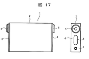
- FIG. 1 is a two-side view illustrating an example of a non-aqueous electrolyte secondary battery in the first embodiment.
- the nonaqueous electrolyte secondary battery 1 has a flat rectangular battery container 2.
- the battery case 2 is sealed by closing the openings at both ends with sealing plates 3 and 4 and welding them by laser welding or the like.
- One sealing plate 4 is provided with a positive electrode terminal 5 and a negative electrode terminal 6 for inputting / outputting electric energy to / from the non-aqueous electrolyte secondary battery 1.
- the sealing plate 4 is provided with a gas discharge valve 7 for discharging a gas generated in the battery container 2 and having a high pressure, and a liquid injection port 8 which is sealed after the electrolyte is injected. Yes.
- an electrode group 11 (see FIG. 2) is accommodated together with the electrolytic solution.
- FIG. 2 is a two-side view showing an example of the electrode group in the present embodiment.
- the electrode group 11 has a flat shape that can be accommodated in the battery case 2.
- the electrode group 11 includes a wound body in which the positive electrode 21 and the negative electrode 31 are wound with separators 41 and 42 interposed therebetween.
- the electrode group 11 is formed in a flat shape by being wound around a flat plate-shaped shaft core 12, and is curved in a semicircular arc shape at the flat portions 11A and the ends of the flat portions 11A that are disposed at positions facing each other. It has a pair of curved parts 11B and 11B.
- a plurality of positive electrode current collecting tabs 23 and negative electrode current collecting tabs 33 are arranged on one side of the flat portion 11 ⁇ / b> A and in the winding axis direction of the electrode group 11.
- the plurality of positive electrode current collecting tabs 23 and negative electrode current collecting tabs 33 are arranged on one side in the thickness direction of the electrode group 11, and are further divided into two portions, one closer to the curved portion 11B and the other closer to the curved portion 11B. Is arranged. Each of the electrodes 11 is collected in the thickness direction and electrically connected to the positive electrode terminal 5 and the negative electrode terminal 6 shown in FIG.
- FIG. 3 is an enlarged perspective view of a connection portion between the current collecting tab and the connection terminal in the present embodiment.
- the positive electrode terminal 5 is made of, for example, an aluminum alloy, and a base end portion is inserted and fixed in a mounting hole 12 a provided in an end portion of the shaft core 12. And the some positive electrode current collection tab 23 is welded by the ultrasonic welding or the resistance welding in the state put together in the thickness direction.
- the positive electrode terminal 5 is threaded on the outer periphery of the front end portion, and the front end portion is inserted into an opening (not shown) of the sealing plate 4 so as to protrude to the outside of the battery container 2, via a sealing material. Then, the screw cap (not shown) is screwed to be fixed to the sealing plate 4.
- the negative electrode terminal 6 (see FIG. 1) is made of, for example, a copper alloy. Although not specifically illustrated, the negative electrode terminal 6 is welded by ultrasonic welding or resistance welding in a state where a plurality of negative electrode current collecting tabs 33 are gathered in the thickness direction, like the positive electrode terminal 5. Is fixed to the sealing plate 4 in a state of protruding outward from the battery container 2.
- the electrode group 11 is configured by winding a plurality of positive electrode sheets 22 and a plurality of negative electrode sheets 32 side by side in the length direction.
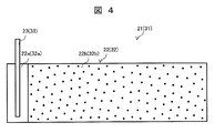
- FIG. 4 is a diagram illustrating an example of the positive electrode sheet in the present embodiment, and schematically illustrates the configuration of one positive electrode sheet. Since the positive electrode sheet 22 and the negative electrode sheet 32 have the same shape, the reference numeral of the negative electrode sheet 32 is attached in parentheses next to the reference numeral of the positive electrode sheet 22 in FIG. .
- the positive electrode 21 has a plurality of positive electrode sheets 22.
- the positive electrode sheet 22 includes an elongated sheet-like positive electrode current collector 22a having a positive electrode active material layer 22b, and a positive electrode current collector tab protruding in the width direction of the positive electrode current collector 22a at the end in the length direction of the positive electrode current collector 22a. 23.
- the positive electrode sheet 22 has an uncoated part at the end in the length direction. In the uncoated portion, the positive electrode active material layer 22b is not provided, and the positive electrode current collector 22a is exposed.
- the positive electrode sheet 22 is formed through a step of applying a slurry-like positive electrode active material on both surfaces of the positive electrode current collector 22a, a step of drying after coating, and a rolling step of pressing after drying.
- the positive electrode active material includes a lithium composite oxide represented by LiMO 2 having a layered structure or LiM 2 O 4 having a spinel structure (M is an arbitrary transition metal element), and LiMPO 4 (M is an arbitrary transition metal element).
- a carbon material such as graphite or acetylene black for improving conductivity is used for the powder of polyanion having an olivine structure represented by Then, a slurry-like positive electrode mixture is prepared by uniformly mixing a polymer resin such as polyvinylidene fluoride dissolved in a solvent such as normal methylpyrrolidone as a binder with a positive electrode active material, and a positive electrode current collector 22a. Each side is coated with a predetermined thickness. And after drying, it rolls by press work etc. and makes it predetermined thickness.
- the positive electrode current collector tab 23 is for electrically connecting the positive electrode current collector 22a and the positive electrode terminal 5, and is provided separately from the positive electrode current collector 22a.
- the uncoated part is joined by ultrasonic welding or resistance welding.
- the positive electrode current collector tab 23 is made of a material that can be joined to the positive electrode current collector 22a by, for example, ultrasonic welding or resistance welding, such as an aluminum alloy, and is configured by a member different from the positive electrode current collector 22a.
- the negative electrode 31 has a plurality of negative electrode sheets 32.
- the negative electrode sheet 32 includes an elongated sheet-like negative electrode current collector 32a having a negative electrode active material layer 32b, and a negative electrode current collector tab protruding in the width direction of the negative electrode current collector 32a at the lengthwise end of the negative electrode current collector 32a. 33.
- the negative electrode sheet 32 has an uncoated part at the end in the length direction. The uncoated portion is not provided with the negative electrode active material layer 32b, and the negative electrode current collector 32a is exposed.
- the negative electrode sheet 32 is formed through a step of coating a slurry-like negative electrode active material on both surfaces of the negative electrode current collector 32a, a step of drying after coating, and a rolling step of pressing after drying.
- a copper foil of about 10 ⁇ m is used for the negative electrode current collector 32a.
- carbon material such as graphite or amorphous carbon, lithium titanate or Si oxide powder is used.
- a polymer resin such as polyvinylidene fluoride as a binder dissolved in a solvent such as normal methylpyrrolidone, or a dispersion of styrene butadiene rubber and carboxymethyl cellulose in water is uniformly mixed with the negative electrode active material.
- a slurry-like negative electrode mixture is produced, and applied to both surfaces of the negative electrode current collector 32a with a predetermined thickness. And after drying, it forms by rolling by press work etc. and making it predetermined thickness.
- the negative electrode current collecting tab 33 is for electrically connecting the negative electrode current collector 32a and the negative electrode terminal 6 to each other by ultrasonic welding or resistance welding on an uncoated portion of the negative electrode current collector 32a. It is joined.
- the negative electrode current collector tab 33 is made of a material that can be joined to the negative electrode current collector 32a by, for example, ultrasonic welding or resistance welding, such as a nickel alloy, and is configured by a member different from the negative electrode current collector 32a.
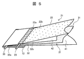
- FIG. 5 is a diagram illustrating an example of a method for producing a wound body in the present embodiment
- FIG. 6 is a diagram illustrating an example of a state in which the first single portion of the wound body in the present embodiment is completed
- FIG. It is a figure which shows an example of the state which complete
- the winding start end portions of the two separators 41 and 42 are fixed to the shaft core 12.
- Each winding start end portion is heat-welded to the shaft core 12 in a state of being overlapped with each other, or is fixed using an adhesive tape or the like.
- the winding start end of one negative electrode sheet 32 is inserted between the outer peripheral surface of one separator 41 and the inner peripheral surface of the other separator 42, and the outer periphery of the other separator 42 is inserted.
- the winding start end of one positive electrode sheet 22 is arranged on the surface.
- the negative electrode sheet 32 has an end portion where the negative electrode current collector 32a is exposed and the negative electrode current collector tab 33 is provided as a winding start end portion, and the positive electrode sheet 22 is exposed when the positive electrode current collector 22a is exposed.
- the end portion on which the current collecting tab 23 is provided is the winding start end portion.
- each winding start end portion is arranged with respect to the shaft core 12.
- the shaft core 12 is rotated so that one separator 41, the positive electrode sheet 22, the other separator 42, and the negative electrode sheet 32 are wound in a state of being overlapped with each other, as shown in FIG.
- the wound body 11a in which the first single portion is wound is formed.
- new separators 41 and 42, the positive electrode sheet 22, and the negative electrode sheet 32 are wound outside the wound body 11a, and this is repeated a plurality of times to perform multiple winding.
- An electrode group 11 made of the wound body is formed.
- positioned at the outermost periphery of the electrode group 11 is fixed with an adhesive tape etc., so that winding cannot be unwound.
- the plurality of positive electrode sheets 22 and the plurality of negative electrode sheets 32 are respectively wound in the length direction, and the plurality of positive electrode current collecting tabs 23 and the plurality of negative electrode current collecting tabs 33 are respectively wound from the flat portion 11A. It is possible to obtain the electrode group 11 protruding to one side in the axial direction.
- FIG 8 to 10 are sectional views showing an example of the configuration of the wound body in the present embodiment.
- the above-described positive electrode sheet 22, negative electrode sheet 32, and separators 41 and 42 are grouped as one group and wound so as to be completed for each group. There is.
- the inner group wound first and the outer group wound next are separated from the inside toward the outside by the separator 41, the negative electrode sheet 32, the separator 42,
- the positive electrode sheets 22 are wound in an overlapped order, and the outermost periphery of the positive electrode sheet 22 is covered with the negative electrode sheet 32 with the separator 41 therebetween, and the outermost periphery of the negative electrode sheet 32 is further covered with the separator 41.
- the electrode group 11 is constituted by a wound body in which the plurality of groups are connected in the length direction and wound in multiple directions.
- connection between the inner group wound first and the outer group wound next is connected to the outermost separator 41 of the inner group wound first and the outer wound next. This is done by connecting the winding start ends of the separators 41 of this group.
- the separator can be connected by heat welding, ultrasonic bonding, adhesive, adhesive tape, or the like.
- the insertion order of the separator and the electrode can be wound without changing between the inner group wound first and the outer group wound next. Therefore, the wound body once wound can be continuously wound without removing it once, and the electrode group 11 can be easily created.
- the first group wound directly on the shaft core 12 has the same configuration as the group shown in FIG.
- the group has a configuration in which the positive electrode sheet 22, the separator 41, the negative electrode sheet 32, and the separator 42 are stacked in this order from the inside toward the outside.
- the winding end portion has a configuration in which the negative electrode sheet 32 covers the outer periphery of the winding end end portion of the positive electrode sheet 22, and the separator 41 covers the outer side of the outermost negative electrode sheet 32. .
- At least one or more second groups other than the first group wound directly on the shaft core 12 are in relation to the first or second group disposed inside. Is wound around the outside.
- the electrode group 11 has a configuration in which a first group and at least one or more second groups are connected in the length direction and wound in multiple layers.
- the wound body 11a shown in FIG. 9 has an outer group (first) wound next with respect to the outermost periphery of the negative electrode sheet 32 of the inner group (first or second group) wound first. Winding can be started with the innermost circumference of the positive electrode sheet 22 included in the (two groups) facing each other. Therefore, the outermost periphery of the negative electrode sheet 32 included in the inner group wound first is prevented from facing the innermost periphery of the negative electrode sheet 22 included in the outer group wound next.
- the outermost periphery of the negative electrode sheet 32 included in the inner group to be rotated can be used without waste. Therefore, as compared with the embodiment shown in FIG.
- the innermost periphery of the negative electrode sheet 32 included in the inner group wound first and the innermost periphery of the negative electrode sheet 22 included in the outer group wound next. Can be shortened, and the number of turns of the positive electrode 21 and the negative electrode 31 can be increased by that amount to increase the battery capacity.
- separators 41 and 42 are continuous in the length direction, and a plurality of positive electrode sheets 22 and negative electrode sheets 32 are interposed therebetween. is there.
- the wound body 11a shown in FIG. 10 is continuous without cutting the two separators 41 and 42, and the plurality of positive electrode sheets 22 and the plurality of negative electrode sheets 32 are respectively interposed between the two separators 41 and 42. It has a configuration in which it is wound with a predetermined interval in the length direction.
- the plurality of positive electrode sheets 22 are interposed between the outer peripheral surface of one separator 41 facing each other and the inner peripheral surface of the other separator 42, and the plurality of negative electrode sheets 32 are connected to the outer peripheral surface of the other separator facing each other. It is interposed between the inner peripheral surface of one separator.
- the negative electrode sheet 32 wound inward can be wound with the positive electrode sheet 22 facing the outer side, and the negative electrode sheet 32 and separators 41, 42 can be wound. Can prevent repeated winding. Therefore, more positive electrode sheets 22 and negative electrode sheets 32 can be wound, and the battery capacity can be increased. Further, it is not necessary to connect the plurality of separators 41 and 42 in the length direction, and the electrode group 11 can be easily manufactured.
- FIG. 11 and FIG. 12 are two views showing an example of the electrode group in the present embodiment.
- the positive electrode current collecting tab 23 and the negative electrode current collecting tab 33 are arranged on one curved portion 11B side and the other curved portion 11B side on one side in the thickness direction of the flat portion 11A.
- the position of the positive electrode current collection tab 23 and the negative electrode current collection tab 33 is not limited to the position of FIG. 2, A various change is possible. .
- the positive electrode current collecting tab 23 and the negative electrode current collecting tab 33 are arranged at positions spaced apart from one side and the other side in the thickness direction of the flat portion 11A, and on the one curved portion 11B side. It is good also as a structure arrange
- the positions of the positive electrode current collecting tab 23 and the negative electrode current collecting tab 33 are the positions of the winding start end portions with respect to the shaft core 12 for each positive electrode and each negative electrode when the positive electrode sheet 22 and the negative electrode sheet 32 are wound around the wound body 11a. Can be aligned by matching.
- only the positive electrode current collecting tab 23 and the negative electrode current collecting tab 33 are arranged at positions separated from one side and the other side in the thickness direction of the flat portion 11A, and only one curved portion 11B. It does not have to be separated from the side and the other curved portion 11B side.
- a plurality of positive electrode current collecting tabs 23 arranged scattered on one side in the thickness direction of the flat portion 11A are respectively joined to a positive electrode current collector plate (not shown), and the positive electrode current collector plate is connected to the positive electrode terminal 5. Connect to.
- a plurality of negative electrode current collecting tabs 33 arranged on the other side in the thickness direction of the flat portion 11A are joined to a negative electrode current collector plate (not shown), and the negative electrode current collector plate is connected to the negative electrode terminal 6. .
- the positions thereof are the one surface and the other surface of the shaft core 12.
- the positions of the positive electrode current collection tabs 23 and the negative electrode current collection tabs 33 are separated from each other on the one curved portion 11B side and the other curved portion 11B side, and Since it is not necessary to align the positions of the negative electrode current collecting tabs 33, it is easy to manufacture the electrode group 11.
- the positive electrode sheet 22 and the negative electrode sheet 32 are separately provided on the uncoated portions at the end portions in the length direction of the positive electrode current collector 22a and the negative electrode current collector 32a.
- the structure of the positive electrode sheet 22 and the negative electrode sheet 32 is limited to the structure shown by FIG. Various modifications are possible.
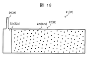
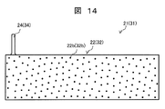
- FIG. 13 and FIG. 14 are diagrams showing examples of electrodes in the present embodiment.
- the negative electrode is not shown in FIGS. 13 and 14 by attaching the negative electrode symbol in parentheses next to the positive electrode symbol. Also, the description of the configuration of the negative electrode is omitted.
- the positive electrode current collecting tab 24 may be formed integrally with the positive electrode current collector 22a.
- the positive electrode current collecting tab 24 is formed by cutting off a part of the uncoated portion of the positive electrode current collector 22a.
- the positive electrode current collecting tab 24 has R processing applied to the root portion and the tip portion protruding from the side edge of the positive electrode current collector 22a. Due to the R processing, the base portion is broken during handling in the assembly process, or when the positive electrode current collector tab 24 is left to be cut off, the positive electrode current collector tab 24 is not separated from the end material. Cutting can be prevented.
- the positive electrode active material layer 22b may be formed up to the end in the length direction of the positive electrode current collector 22a. According to such a configuration, since the positive electrode current collecting tab 24 is not rolled by the rolling process, a difference in elongation occurs between the positive electrode current collecting tab 24 and the coated portion, but the lengthwise end of the positive electrode sheet 22 provided with the positive electrode current collecting tab 24 is provided. Therefore, the influence on the whole length direction of the positive electrode sheet 22 is slight and there is no influence on winding.
- the electrode 101 provided with a solid portion (current collector exposed portion) having a constant width in the width direction has a configuration in which the current collector foil 101a also serves as a current collector tab. Therefore, when this electrode is rolled with a rolling strength of a certain level or more, the plain portion is not rolled, and only the active material coated portion 101b coated with the active material is rolled. Accordingly, a difference in elongation occurs in the width direction of the current collector foil 101a, and the entire electrode 101 is curved as shown in FIG. 16, and it is difficult to wind the electrode as an electrode.
- the active material is applied in the width direction of the positive electrode current collector 22a. Even after passing, there is no difference in the elongation of the current collector 22a, and the bending as described above does not occur.
- the difference in the elongation of the current collector 22a similar to that of the electrode of the conventional configuration occurs only in the tab portion. However, since only the end portion in the length direction is affected, the influence is slight as described above. There is no impact on
- a solid portion is provided at one end in the width direction of the electrode 101, and a current collecting component is electrically connected to this portion.
- a configuration is adopted in which a current collection path is secured over the entire length direction of the electrode, and the internal resistance of the battery is reduced by shortening the charge transfer distance in the active material layer.
- the metal foil of the active material coated portion 101b is rolled, but the metal foil of the uncoated portion is The belt-shaped electrode 101 is curved as shown in FIG.
- the curvature of the electrode 101 does not become so great when the rolling strength is low, so that no problem occurs in the subsequent winding process.
- the rolling strength is high, the curvature becomes large and a spiral wound body cannot be produced.
- the rolling process has to be processed with a relatively low strength, and the density of the active material coating layer cannot be sufficiently improved, so that it has been difficult to obtain a battery with a high energy density.
- uncoated portions are cut into strips to form narrow leads, and these leads are electrically connected to external terminals to extract or input electric energy from the active material as a power storage element. ing.
- This method can reduce the above-mentioned curve than when the uncoated part is a plain part of equal width, but the width of the uncoated part cannot be made zero, and the curve cannot be completely avoided. It is difficult to connect the lead led out from the wound body in a petal shape to the current collecting component connected to the external terminal.
- the electrode group 11 in the present embodiment includes a plurality of positive electrode sheets 22 having positive electrode current collecting tabs 23 at the lengthwise ends of the positive electrode current collectors 22a, and the length direction of the negative electrode current collectors 32a.
- a plurality of negative electrode sheets 32 each having a negative electrode current collecting tab 33 at the end thereof are arranged in the length direction and wound.
- the positive electrode sheet 22 is provided with a positive electrode current collector tab at the lengthwise end of the positive electrode current collector 22a
- the negative electrode sheet 32 is provided with a negative electrode current collector tab at the lengthwise end of the negative electrode current collector 32a. Therefore, even if the rolling strength is increased in the rolling process, the positive electrode sheet and the negative electrode sheet are not likely to be bent, and can be easily wound, and a spiral wound body can be created. Therefore, the rolling process can be processed with relatively high strength, the density of the active material layer can be sufficiently improved, and a battery with high energy density can be obtained.
- each winding start end has a positive electrode active material layer 22b and a negative electrode active material layer 32b. And has higher rigidity than the end portion at the end of the firing. Therefore, as shown in FIG. 6, when the wound body 11a is formed, it can be easily inserted between the separators 41 and 42, can be securely placed in a proper position while preventing bending, and can be easily manufactured. It becomes possible.
- the electrode group 11 includes electrodes having the same polarity constituting the electrode group 11 by a plurality of electrode sheets provided with current collecting tabs at end portions in the length direction. It has the structure which comprises and winds in multiple. That is, the plurality of positive electrode sheets 22 and the plurality of negative electrode sheets 32 each having the positive electrode current collecting tab 23 and the negative electrode current collecting tab 33 are arranged in the length direction and wound.
- the winding length of the positive electrode sheet 22 and the negative electrode sheet 32 is prevented from being increased, and the distance that the charge moves in the active material layer accordingly, that is, electricity is generated.
- the current collection path from the place to the place to take out can be shortened. Therefore, it is possible to prevent the internal resistance of the battery from increasing and improve the output performance.
- the positive electrode sheet 22 and the negative electrode sheet 32 are provided with current collecting tabs 23 (24) and 33 (34) at end portions in the length direction, the active material layer can be rolled with high strength. Therefore, the nonaqueous electrolyte secondary battery 1 having a high energy density can be obtained.
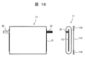
- FIG. 17 to FIG. 23 are diagrams showing an example of the nonaqueous electrolyte secondary battery in the present embodiment.
- the same components as those in the first embodiment described above are denoted by the same reference numerals, and detailed description thereof is omitted.
- the electrode group 11 has a configuration in which a positive electrode current collecting tab 23 is disposed on one side in the winding axis direction and a negative electrode current collecting tab 33 is disposed on the other side in the winding axis direction. have.
- the positive electrode current collecting tab 23 and the negative electrode current collecting tab 33 are provided on the flat portion 11A of the electrode group 11 so as to be divided into one side and the other side in the winding axis direction. And it arrange
- the nonaqueous electrolyte secondary battery 1 having such an electrode group 11 is provided with a positive electrode terminal 5 on one sealing plate 3 and a negative electrode terminal 6 on the other sealing plate 4.
- the positive electrode current collector tab 23 and the negative electrode current collector tab 33 are electrically connected to the positive electrode terminal 5 and the negative electrode terminal 6.
- FIG. 19 is a diagram illustrating an example of a method for producing a wound body in the present embodiment
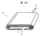
- FIG. 20 is a diagram illustrating an example of a state in which the first single portion of the wound body in the present embodiment has been completed
- FIG. It is a figure which shows an example of the state which complete
- the winding start end portions of the two separators 41 and 42 are fixed to the shaft core 13, and the winding start end portion of one negative electrode sheet 32 is connected to the outer peripheral surface of one separator 41 as shown in FIG. It is inserted between the inner peripheral surface of the other separator 42, and the winding start end portion of one positive electrode sheet 22 is disposed on the outer peripheral surface of the other separator 42.
- the positive electrode current collecting tab 23 and the negative electrode current collecting tab 33 are separated from the flat portion 11A of the electrode group 11 into one side and the other side in the winding axis direction, respectively.
- Each winding start end portion is arranged with respect to the shaft core 12 so as to protrude.
- the shaft core 12 is rotated and the one separator 41, the positive electrode sheet 22, the other separator 42, and the negative electrode sheet 32 are wound in a mutually overlapping state, and as shown in FIG. A wound body 11a is formed in which is wound.
- new separators 41 and 42, the positive electrode sheet 22, and the negative electrode sheet 32 are wound outside the wound body 11a, and this is repeated a plurality of times to perform multiple winding.
- An electrode group 11 made of the wound body is formed. The method shown in FIGS. 8 to 10 described above can be used as a method of performing multiple winding.
- 22 and 23 are two views showing an example of an electrode group in the present embodiment.
- the positive electrode current collecting tab 23 and the negative electrode current collecting tab 33 are arranged close to one side in the thickness direction of the flat portion 11A and one curved portion 11B.
- the positions of the positive electrode current collecting tab 23 and the negative electrode current collecting tab 33 are not limited to the positions in FIG. 18, and various changes can be made.
- the positive electrode current collecting tab 23 and the negative electrode current collecting tab 33 may be arranged separately on one side and the other side in the thickness direction of the flat portion 11A.
- the positive electrode current collecting tab 23 and the negative electrode current collecting tab 33 may be simply disposed on the flat portion 11A, and may be divided into one side and the other side in the thickness direction, or one curved portion. It is not necessary to put it close to the 11B side.
- a plurality of positive electrode current collecting tabs 23 scattered and arranged in the flat portion 11 ⁇ / b> A are joined to a positive electrode current collector plate (not shown), and the positive electrode current collector plate is connected to the positive electrode terminal 5.
- the plurality of negative electrode current collecting tabs 33 scattered and arranged in the flat portion 11 ⁇ / b> A are respectively joined to a negative electrode current collecting plate (not shown), and the negative electrode current collecting plate is connected to the negative electrode terminal 6.
- the winding start end portion is one side surface of the shaft core 12 or Since it is only necessary to arrange the electrode group 11 on the other surface, the electrode group 11 can be easily manufactured.
- a plurality of current collecting paths can be secured from the wound body, and a non-aqueous electrolyte secondary battery excellent in output performance can be obtained.
- the nonaqueous electrolyte secondary battery which also has a high energy density by comprising a wound body from the electrode which can roll an active material layer with high intensity
- the non-aqueous electrolyte secondary battery 1 in the present embodiment a plurality of current collecting paths can be secured, the winding lengths of the positive electrode sheet 22 and the negative electrode sheet 32 are prevented from being increased, and the active material layer accordingly It is possible to prevent the distance that the electric charge moves inside, that is, the length of the current collection path from the place where electricity is generated to the place where electricity is taken out. Therefore, it is possible to prevent the internal resistance of the battery from increasing and improve the output performance. Moreover, since the positive electrode sheet 22 and the negative electrode sheet 32 are provided with current collecting tabs 23 and 33 at the lengthwise ends, the active material layer can be rolled with high strength. Therefore, the nonaqueous electrolyte secondary battery 1 having a high energy density can be obtained.
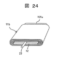
- FIG. 24 is a diagram showing an example of the nonaqueous electrolyte secondary battery in the present embodiment.
- the same components as those in the second embodiment described above are denoted by the same reference numerals, and detailed description thereof is omitted.
- the positive electrode 21 (first electrode sheet) 22 shown in FIG. 4 is used as the positive electrode 21, and the negative electrode 31 (second electrode sheet) having the shape of the electrode 101 shown in FIG. 15 is used as the negative electrode 31.
- FIG. 24 shows a wound body 11b created using two sheets of different types.
- One negative electrode sheet has an elongated sheet-like negative electrode current collector having an active material layer, and has a structure in which a plain portion 101a where the negative electrode current collector is exposed is provided at an end in the width direction of the negative electrode current collector.
- the electrode group has a configuration in which a plurality of positive electrode sheets 22 are arranged in the length direction and wound with a separator between one negative electrode sheet.
- FIG. 15 The structure of FIG. 15 in which the plain portion 101a is provided at one end in the width direction of the electrode 101 can be more easily produced than using an electrode sheet of the type shown in FIG. For this reason, when a high mixture density is not required for one of the electrodes, the formation of the one electrode is facilitated by the structure shown in FIG.
- the current collecting area is increased by using an electrode sheet having a structure in which a solid portion is provided at one end in the width direction of the electrode 101, the resistance in the current collecting path can be reduced. Therefore, it may be preferable to use an electrode sheet having the structure of the electrode 101 when the conductivity of the active material is low.
- the positive electrode sheet 22 when a higher mixture density is required on the positive electrode side, it is preferable to use the positive electrode sheet 22 having the shape shown in FIG. 4, and a higher mixture density is not required on the negative electrode side.
- the negative electrode sheet the electrode 101 provided with a solid portion (current collector exposed portion) having a certain width in the width direction.
- the negative electrode sheets which are the structures of the separators 41 and 42 and the electrode 101, are respectively continuous in the length direction, and a plurality of positive electrode sheets 22 are interposed therebetween.
- the wound body 11b shown in FIG. 24 includes a plurality of positive electrodes 41 and 42 which are continuously formed without cutting the two sheets of separators 41 and 42 and the negative electrode sheet which is the structure of the electrode sheet 101.
- the sheet 22 has a configuration in which the sheet 22 is wound with a predetermined interval in the length direction.
- the plurality of positive electrode sheets 22 are interposed between the outer peripheral surface of one separator 41 and the inner peripheral surface of the other separator 42 facing each other.
- the positive electrode side has the structure shown in FIG. 4 and the negative electrode side has the structure shown in FIG. 15, but the positive electrode side may have the structure shown in FIG. 15 and the negative electrode side may have the structure shown in FIG. .
- the number of repetitions when winding the electrode is appropriately designed depending on how many current collecting tabs are required per unit length of the electrode. If the unit length is shortened, the current path increases, so that the battery can easily handle high output. If the unit length is long, the active material occupied volume in the battery can be increased, so that the battery has a high energy density. it can.
- the above-described battery structure is an example of a battery structure to which the present invention is applied, and should be appropriately selected including other structures depending on the arrangement or the like when these single cells are used as an assembled battery. It does not limit the requirements of the present invention.
- the present invention is not limited to the above-described embodiments, and various designs can be made without departing from the spirit of the present invention described in the claims. It can be changed.
- the above-described embodiment has been described in detail for easy understanding of the present invention, and is not necessarily limited to one having all the configurations described.
- a part of the configuration of an embodiment can be replaced with the configuration of another embodiment, and the configuration of another embodiment can be added to the configuration of an embodiment.
Landscapes
- Chemical & Material Sciences (AREA)
- Chemical Kinetics & Catalysis (AREA)
- Electrochemistry (AREA)
- General Chemical & Material Sciences (AREA)
- Engineering & Computer Science (AREA)
- Manufacturing & Machinery (AREA)
- Connection Of Batteries Or Terminals (AREA)
- Secondary Cells (AREA)
Abstract
L'objet de la présente invention est de pourvoir à une cellule secondaire à électrolyte non aqueux présentant une excellente performance de sortie. Dans la cellule secondaire à électrolyte non aqueux (1) selon l'invention, une électrode positive (21) présente une pluralité de feuilles d'électrode positive (22) comprenant un collecteur de courant d'électrode positive (22a) qui se présente sous la forme d'une feuille rectangulaire et présente une couche de substance active d'électrode positive (22b), et une patte de collecteur de courant d'électrode positive (23) qui fait saillie dans la direction de la largeur du collecteur de courant d'électrode positive (22a) au niveau du bord dans le sens de la longueur du collecteur de courant d'électrode positive (22a). L'électrode négative (31) présente une pluralité de feuilles d'électrode négative (32) comprenant un collecteur de courant d'électrode négative (32a) qui se présente sous la forme d'une feuille rectangulaire et présente une couche de substance active d'électrode négative (32b), et une patte de collecteur de courant d'électrode négative (33) qui fait saillie dans la direction de la largeur du collecteur de courant d'électrode négative (32a) au niveau du bord dans le sens de la longueur du collecteur de courant d'électrode négative (32a). En outre, un groupe d'électrodes (11) présente une configuration dans laquelle la pluralité de feuilles d'électrode positive (22) et la pluralité de feuilles d'électrode négative (32) sont alignées dans le sens de la longueur et sont enroulées ensemble.
Priority Applications (2)
| Application Number | Priority Date | Filing Date | Title |
|---|---|---|---|
| PCT/JP2013/063994 WO2014188501A1 (fr) | 2013-05-21 | 2013-05-21 | Cellule secondaire à électrolyte non aqueux |
| JP2015517950A JPWO2014188501A1 (ja) | 2013-05-21 | 2013-05-21 | 非水電解液二次電池 |
Applications Claiming Priority (1)
| Application Number | Priority Date | Filing Date | Title |
|---|---|---|---|
| PCT/JP2013/063994 WO2014188501A1 (fr) | 2013-05-21 | 2013-05-21 | Cellule secondaire à électrolyte non aqueux |
Publications (1)
| Publication Number | Publication Date |
|---|---|
| WO2014188501A1 true WO2014188501A1 (fr) | 2014-11-27 |
Family
ID=51933092
Family Applications (1)
| Application Number | Title | Priority Date | Filing Date |
|---|---|---|---|
| PCT/JP2013/063994 Ceased WO2014188501A1 (fr) | 2013-05-21 | 2013-05-21 | Cellule secondaire à électrolyte non aqueux |
Country Status (2)
| Country | Link |
|---|---|
| JP (1) | JPWO2014188501A1 (fr) |
| WO (1) | WO2014188501A1 (fr) |
Cited By (8)
| Publication number | Priority date | Publication date | Assignee | Title |
|---|---|---|---|---|
| CN105938890A (zh) * | 2015-03-02 | 2016-09-14 | 三星Sdi株式会社 | 可再充电电池 |
| WO2017047353A1 (fr) * | 2015-09-14 | 2017-03-23 | 日立マクセル株式会社 | Pile rechargeable à électrolyte non aqueux |
| CN109273757A (zh) * | 2017-07-17 | 2019-01-25 | 通用汽车环球科技运作有限责任公司 | 极耳区域增加的电池单元及其制造方法和设备 |
| CN112567555A (zh) * | 2018-08-09 | 2021-03-26 | 株式会社村田制作所 | 二次电池、电池包、电动车辆、蓄电系统、电动工具及电子设备 |
| CN113258123A (zh) * | 2021-06-25 | 2021-08-13 | 珠海冠宇电池股份有限公司 | 一种卷绕式电芯和电池 |
| JP2021177490A (ja) * | 2017-04-14 | 2021-11-11 | エルジー・ケム・リミテッド | 二次電池及びその二次電池の製造方法 |
| CN114080709A (zh) * | 2019-07-30 | 2022-02-22 | 株式会社村田制作所 | 二次电池、电池包、电子设备、电动工具、电动式航空器以及电动车辆 |
| CN116565294A (zh) * | 2023-06-01 | 2023-08-08 | 淮北市千锂鸟新能源科技有限公司 | 多极耳圆柱锂离子电芯、电池的制造方法及其电池 |
Citations (6)
| Publication number | Priority date | Publication date | Assignee | Title |
|---|---|---|---|---|
| JP2000277155A (ja) * | 1999-03-25 | 2000-10-06 | Hitachi Ltd | 非水電解液二次電池 |
| JP2002164044A (ja) * | 2000-11-24 | 2002-06-07 | Nec Corp | 電極巻回型電池及びその製造方法 |
| JP2006286404A (ja) * | 2005-03-31 | 2006-10-19 | Dainippon Printing Co Ltd | 非水電解液二次電池用電極板の正極板と負極板の組み合わせ、その正極板と負極板の製造方法、および非水電解液二次電池 |
| JP2011014238A (ja) * | 2009-06-30 | 2011-01-20 | Panasonic Corp | 非水電解質二次電池用電極群及び非水電解質二次電池 |
| JP2012174411A (ja) * | 2011-02-18 | 2012-09-10 | Toshiba Corp | 電池 |
| JP2012195312A (ja) * | 2012-07-13 | 2012-10-11 | Gs Yuasa Corp | 電池 |
Family Cites Families (6)
| Publication number | Priority date | Publication date | Assignee | Title |
|---|---|---|---|---|
| JP3943822B2 (ja) * | 2000-10-26 | 2007-07-11 | 功 松本 | 電池用渦巻状電極群及び電池 |
| JP5100441B2 (ja) * | 2008-02-26 | 2012-12-19 | 株式会社東芝 | 非水電解質電池 |
| JP2010118315A (ja) * | 2008-11-14 | 2010-05-27 | Toshiba Corp | 非水電解質電池 |
| JP5762676B2 (ja) * | 2009-09-25 | 2015-08-12 | 株式会社東芝 | 電極及び非水電解液電池 |
| JP2011171079A (ja) * | 2010-02-17 | 2011-09-01 | Toshiba Corp | 電池 |
| EP2757624A4 (fr) * | 2011-09-14 | 2015-04-22 | Gs Yuasa Int Ltd | Batterie cylindrique |
-
2013
- 2013-05-21 JP JP2015517950A patent/JPWO2014188501A1/ja active Pending
- 2013-05-21 WO PCT/JP2013/063994 patent/WO2014188501A1/fr not_active Ceased
Patent Citations (6)
| Publication number | Priority date | Publication date | Assignee | Title |
|---|---|---|---|---|
| JP2000277155A (ja) * | 1999-03-25 | 2000-10-06 | Hitachi Ltd | 非水電解液二次電池 |
| JP2002164044A (ja) * | 2000-11-24 | 2002-06-07 | Nec Corp | 電極巻回型電池及びその製造方法 |
| JP2006286404A (ja) * | 2005-03-31 | 2006-10-19 | Dainippon Printing Co Ltd | 非水電解液二次電池用電極板の正極板と負極板の組み合わせ、その正極板と負極板の製造方法、および非水電解液二次電池 |
| JP2011014238A (ja) * | 2009-06-30 | 2011-01-20 | Panasonic Corp | 非水電解質二次電池用電極群及び非水電解質二次電池 |
| JP2012174411A (ja) * | 2011-02-18 | 2012-09-10 | Toshiba Corp | 電池 |
| JP2012195312A (ja) * | 2012-07-13 | 2012-10-11 | Gs Yuasa Corp | 電池 |
Cited By (17)
| Publication number | Priority date | Publication date | Assignee | Title |
|---|---|---|---|---|
| CN105938890A (zh) * | 2015-03-02 | 2016-09-14 | 三星Sdi株式会社 | 可再充电电池 |
| WO2017047353A1 (fr) * | 2015-09-14 | 2017-03-23 | 日立マクセル株式会社 | Pile rechargeable à électrolyte non aqueux |
| JPWO2017047353A1 (ja) * | 2015-09-14 | 2018-06-28 | マクセルホールディングス株式会社 | 非水電解質二次電池 |
| US11973177B2 (en) | 2017-04-14 | 2024-04-30 | Lg Energy Solution, Ltd. | Secondary battery and method for manufacturing the same |
| US12278326B2 (en) | 2017-04-14 | 2025-04-15 | Lg Energy Solution, Ltd. | Secondary battery and method for manufacturing the same |
| US12341147B2 (en) | 2017-04-14 | 2025-06-24 | Lg Energy Solution, Ltd. | Secondary battery and method for manufacturing the same |
| JP2021177490A (ja) * | 2017-04-14 | 2021-11-11 | エルジー・ケム・リミテッド | 二次電池及びその二次電池の製造方法 |
| US11652232B2 (en) | 2017-04-14 | 2023-05-16 | Lg Energy Solution, Ltd. | Secondary battery and method for manufacturing the same |
| US12334493B2 (en) | 2017-04-14 | 2025-06-17 | Lg Energy Solution, Ltd. | Secondary battery and method for manufacturing the same |
| JP7341585B2 (ja) | 2017-04-14 | 2023-09-11 | エルジー エナジー ソリューション リミテッド | 二次電池及びその二次電池の製造方法 |
| CN109273757A (zh) * | 2017-07-17 | 2019-01-25 | 通用汽车环球科技运作有限责任公司 | 极耳区域增加的电池单元及其制造方法和设备 |
| CN112567555A (zh) * | 2018-08-09 | 2021-03-26 | 株式会社村田制作所 | 二次电池、电池包、电动车辆、蓄电系统、电动工具及电子设备 |
| CN112567555B (zh) * | 2018-08-09 | 2024-04-09 | 株式会社村田制作所 | 二次电池、电池包、电动车辆、蓄电系统、电动工具及电子设备 |
| CN114080709A (zh) * | 2019-07-30 | 2022-02-22 | 株式会社村田制作所 | 二次电池、电池包、电子设备、电动工具、电动式航空器以及电动车辆 |
| CN113258123A (zh) * | 2021-06-25 | 2021-08-13 | 珠海冠宇电池股份有限公司 | 一种卷绕式电芯和电池 |
| CN116565294B (zh) * | 2023-06-01 | 2024-06-04 | 淮北市千锂鸟新能源科技有限公司 | 多极耳圆柱锂离子电芯、电池的制造方法及其电池 |
| CN116565294A (zh) * | 2023-06-01 | 2023-08-08 | 淮北市千锂鸟新能源科技有限公司 | 多极耳圆柱锂离子电芯、电池的制造方法及其电池 |
Also Published As
| Publication number | Publication date |
|---|---|
| JPWO2014188501A1 (ja) | 2017-02-23 |
Similar Documents
| Publication | Publication Date | Title |
|---|---|---|
| JP5583421B2 (ja) | 角形密閉二次電池及び角形密閉二次電池の製造方法 | |
| JP5082256B2 (ja) | 密閉型蓄電池 | |
| CN110429320B (zh) | 卷绕型电池 | |
| JP5242364B2 (ja) | 扁平形二次電池 | |
| WO2014188501A1 (fr) | Cellule secondaire à électrolyte non aqueux | |
| US9859546B2 (en) | Method for producing an electrochemical bundle of a lithium battery | |
| JP6086240B2 (ja) | 非水電解液電池およびその製造方法 | |
| JP2011003518A (ja) | ワインディング方式の電極積層体の製造方法及びそれによるリチウムイオン二次電池用電極積層体 | |
| CN103081201B (zh) | 二次电池及其制造方法 | |
| KR20010082059A (ko) | 중첩 전기화학 셀 및 그의 제조 방법 | |
| WO2012057335A1 (fr) | Batterie secondaire rectangulaire | |
| JP6045286B2 (ja) | 円筒形蓄電素子 | |
| US9263761B2 (en) | Electrode assembly and rechargeable battery having the same | |
| WO2018168628A1 (fr) | Batterie rechargeable à électrolyte non aqueux | |
| WO2020129881A1 (fr) | Batterie secondaire rectangulaire | |
| US20230052005A1 (en) | Electrode assembly including disconnection preventing layer and method for manufacturing the same | |
| WO2017141613A1 (fr) | Pile rechargeable rectangulaire | |
| JP2012190739A (ja) | 二次電池 | |
| KR101387137B1 (ko) | 전극 조립체 및 이를 포함하는 이차 전지 | |
| WO2012105553A1 (fr) | Batterie secondaire cylindrique | |
| WO2013047515A1 (fr) | Batterie secondaire à électrolyte non aqueux | |
| JP2014086388A (ja) | 組電池及びその製造方法 | |
| JP7832192B2 (ja) | 非水電解質二次電池 | |
| JP7749920B2 (ja) | 蓄電素子 | |
| JP2009187724A (ja) | 捲回式リチウムイオン二次電池 |
Legal Events
| Date | Code | Title | Description |
|---|---|---|---|
| 121 | Ep: the epo has been informed by wipo that ep was designated in this application |
Ref document number: 13885419 Country of ref document: EP Kind code of ref document: A1 |
|
| ENP | Entry into the national phase |
Ref document number: 2015517950 Country of ref document: JP Kind code of ref document: A |
|
| NENP | Non-entry into the national phase |
Ref country code: DE |
|
| 122 | Ep: pct application non-entry in european phase |
Ref document number: 13885419 Country of ref document: EP Kind code of ref document: A1 |