WO2014188564A1 - Dispositif de montage de composant - Google Patents
Dispositif de montage de composant Download PDFInfo
- Publication number
- WO2014188564A1 WO2014188564A1 PCT/JP2013/064375 JP2013064375W WO2014188564A1 WO 2014188564 A1 WO2014188564 A1 WO 2014188564A1 JP 2013064375 W JP2013064375 W JP 2013064375W WO 2014188564 A1 WO2014188564 A1 WO 2014188564A1
- Authority
- WO
- WIPO (PCT)
- Prior art keywords
- component
- mounting
- nozzle
- substrate
- component mounting
- Prior art date
- Legal status (The legal status is an assumption and is not a legal conclusion. Google has not performed a legal analysis and makes no representation as to the accuracy of the status listed.)
- Ceased
Links
Images


Classifications
-
- H—ELECTRICITY
- H05—ELECTRIC TECHNIQUES NOT OTHERWISE PROVIDED FOR
- H05K—PRINTED CIRCUITS; CASINGS OR CONSTRUCTIONAL DETAILS OF ELECTRIC APPARATUS; MANUFACTURE OF ASSEMBLAGES OF ELECTRICAL COMPONENTS
- H05K13/00—Apparatus or processes specially adapted for manufacturing or adjusting assemblages of electric components
- H05K13/04—Mounting of components, e.g. of leadless components
- H05K13/0404—Pick-and-place heads or apparatus, e.g. with jaws
- H05K13/0408—Incorporating a pick-up tool
- H05K13/0409—Sucking devices
-
- H—ELECTRICITY
- H05—ELECTRIC TECHNIQUES NOT OTHERWISE PROVIDED FOR
- H05K—PRINTED CIRCUITS; CASINGS OR CONSTRUCTIONAL DETAILS OF ELECTRIC APPARATUS; MANUFACTURE OF ASSEMBLAGES OF ELECTRICAL COMPONENTS
- H05K13/00—Apparatus or processes specially adapted for manufacturing or adjusting assemblages of electric components
- H05K13/04—Mounting of components, e.g. of leadless components
- H05K13/0404—Pick-and-place heads or apparatus, e.g. with jaws
- H05K13/0408—Incorporating a pick-up tool
- H05K13/041—Incorporating a pick-up tool having multiple pick-up tools
-
- H—ELECTRICITY
- H05—ELECTRIC TECHNIQUES NOT OTHERWISE PROVIDED FOR
- H05K—PRINTED CIRCUITS; CASINGS OR CONSTRUCTIONAL DETAILS OF ELECTRIC APPARATUS; MANUFACTURE OF ASSEMBLAGES OF ELECTRICAL COMPONENTS
- H05K13/00—Apparatus or processes specially adapted for manufacturing or adjusting assemblages of electric components
- H05K13/08—Monitoring manufacture of assemblages
- H05K13/081—Integration of optical monitoring devices in assembly lines; Processes using optical monitoring devices specially adapted for controlling devices or machines in assembly lines
- H05K13/0812—Integration of optical monitoring devices in assembly lines; Processes using optical monitoring devices specially adapted for controlling devices or machines in assembly lines the monitoring devices being integrated in the mounting machine, e.g. for monitoring components, leads, component placement
-
- H—ELECTRICITY
- H05—ELECTRIC TECHNIQUES NOT OTHERWISE PROVIDED FOR
- H05K—PRINTED CIRCUITS; CASINGS OR CONSTRUCTIONAL DETAILS OF ELECTRIC APPARATUS; MANUFACTURE OF ASSEMBLAGES OF ELECTRICAL COMPONENTS
- H05K13/00—Apparatus or processes specially adapted for manufacturing or adjusting assemblages of electric components
- H05K13/08—Monitoring manufacture of assemblages
- H05K13/089—Calibration, teaching or correction of mechanical systems, e.g. of the mounting head
Definitions
- the present invention relates to a component mounting apparatus for mounting a component using a camera, and more particularly to a component mounting apparatus characterized by a component position correction method.
- a large number of electronic components are mounted on a printed circuit board used for electronic equipment.
- the mounting operation of these electronic components is automated by a component mounting apparatus (chip mounter).
- chip mounter chip mounter
- the miniaturization of electronic components is rapidly progressing, and high-speed and high-precision component mounting work is required.
- Patent Document 1 relates to an electronic component mounting apparatus that mounts an electronic component on a substrate. “An electronic component is picked up from a component supply unit by a suction nozzle, and the suction nozzle moves in the XYZ directions and the ⁇ direction around the nozzle axis.
- an electronic component mounting apparatus for transporting and mounting an electronic component held by performing a rotating mounting operation on a substrate
- the pickup nozzle is moved up and down with respect to the component supply unit to take out the electronic component
- the suction nozzle is mounted on the substrate
- the target is picked up, and the transfer head performs normal mounting operation to mount the target on the substrate,
- An image of the mounted target is imaged by a camera that moves integrally with the transfer head and the position is recognized, whereby the amount of displacement in the X and Y directions between the normal mounting position and the actual mounting position is obtained and stored as a position correction parameter.
- a moving position correction step of correcting the movement amount of the suction nozzle in the XY direction by the position correction parameter in the pickup operation and / or mounting operation.
- the ⁇ direction of the suction nozzle In each of the plurality of specific rotation positions, the position correction parameter for each angle is acquired individually, and the position correction parameter for each angle corresponding to the rotation position of the suction nozzle in the ⁇ direction during the pickup operation or mounting operation in the moving position correction step.
- the position of the suction nozzle in the electronic component mounting apparatus characterized by using Correcting method. "Describes the invention (claim 1).
- the present invention provides a target component mounting position using an image sensor that is fixed to a component mounting head actuator and images a component mounting position, and an image of the component mounting position captured by the image sensor. And a data processing unit that detects a difference (mounting error) between the imaged component mounting position and calculates a nozzle correction amount.
- the present invention it is possible to provide a component mounting apparatus that always positions a component with high accuracy with respect to a target mounting position even when the component mounting apparatus is operated for a long time.
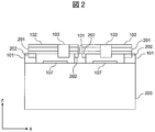
- FIG. 2 is an arrow view of the component mounting apparatus according to the first embodiment of the present invention when an arrow AA cross section shown in FIG. 1 is observed in the direction of the arrow.
- FIG. 3 is a perspective view of a substrate 107 and a head actuator 103 positioned above the substrate 107. It is a flowchart which shows the position correction process by the component mounting apparatus which concerns on Example 1 of this invention. It is explanatory drawing of a template matching process, (a) is the image
- FIG. 6 is an explanatory diagram for raster scanning a substrate image 502 with a template image 501; It is a flowchart of a template matching process. It is a template image of the mounting position of various kinds of components used for a template matching process. It is explanatory drawing which showed the mounting error by xy coordinate. It is explanatory drawing which showed the mounting error by the polar coordinate (r, (theta)). It is explanatory drawing which shows the mode of the head actuator at the time of component mounting. It is a figure which shows the transition of the mounting position by the thermal expansion of a mechanism.
- FIG. 1 It is a figure which shows the relationship of the correction parameter of the nozzle accompanying rotation of the rotor 301, Comprising: (a) is a perspective view, (b) is a top view. It is a perspective view of the head actuator 1301 and the board
- FIG. 1 is a top view of the entire component mounting apparatus.
- FIG. 2 is an arrow view when the component mounting apparatus shown in FIG. 1 is observed in the direction of the arrow along the section AA.
- the substrate 107 on the gantry 203 in FIG. 2 is transported and placed by the substrate guide 106 in the direction of the arrow 110 from the left side in FIG.
- Each Y beam 101 is provided with an actuator 202 such as a linear motor shown in FIG.
- a total of four X beams 102 are arranged on the Y beam 101.
- the X beam 102 is moved in the direction of the arrow 120 by the actuator 202 shown in FIG.
- Each X beam 102 is provided with an actuator 201 such as a linear motor.
- the actuator 201 is provided with a head actuator 103 that mounts electronic components on the substrate 107.
- the head actuator 103 is driven in the direction of the arrow 121 by the actuator 201.
- the component supply device 104 that supplies electronic components to the head actuator 103 is disposed at both ends of the Y beam 101.
- the head actuator is moved directly above the component supply device 104 by the X-beam actuator 201 and the Y-beam actuator 202, and the electronic component is transferred from the component supply device 104. Get replenished.
- a total of four component orientation confirmation cameras 105 for confirming the orientation of the electronic components supplied to the nozzles from below the nozzles are arranged between the three Y beams 101. Further, the control unit 108 performs processing and control of the various operations described above and processing and control of various operations described later.
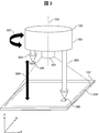
- FIG. 3 is a perspective view of the substrate 107 and the head actuator 103 positioned thereabove.
- the upper end of the nozzle 303 is fixed to the rotor 301 so that the front end faces downward.
- the nozzle 303 moves up and down in the Z-axis direction (the direction of the arrow 308) to supply and mount components.
- the rotor 301 can be rotated in the direction of an arrow 307 by a predetermined angle with the rotation center axis 350 of the rotor 301 as the center axis.
- the camera 304 is fixed on the rotation center 350 of the rotor 301 and has a structure that does not rotate.
- the nozzle 303 vacuum-sucks the component 305 at its tip.
- the postures of the sucked electronic components are respectively confirmed by the component posture confirmation camera 105. If a tilt is detected in the posture of the electronic component, the rotor 301 rotates to adjust the tilt of the electronic component.
- the camera 304 mounted on the head actuator is fixed to the rotor 301 so that the imaging surface faces downward, and images the substrate 107 and the mounted component 360.
- the imaging range 306 of the camera 304 at this time is as shown in FIG.
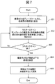
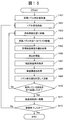
- FIG. 4 is a flowchart illustrating a position correction process performed by the component mounting apparatus according to the first embodiment.
- step 401 a component mounting test is performed using a test board before starting a component mounting operation, and an initial nozzle correction value is acquired and stored in the control unit.
- step 402 the nozzle 303 holds the component 305 in the component supply unit 104.
- step 403 the head actuator 103 moves to the component mounting position by the actuators 201 and 202 while holding the component 305.
- step 404 the board 107 is imaged by the camera 304 to acquire a component mounting location, and the initial nozzle correction value obtained in step 401 or the nozzle correction value obtained in step 408 described later is added to obtain the target component mounting. Position.
- step 405 the component 305 is mounted at the target component mounting position obtained in step 404.
- step 406 the mounted component 360 is imaged by the camera 304 to acquire a component mounting location.
- step 407 the control unit 108 detects the nozzle position coordinates at the time of mounting and the ideal nozzle position coordinates from the image obtained in step 406, and calculates a mounting error.
- step 408 the control unit 108 obtains a nozzle correction value for the next mounting by calculating an average value of the mounting error calculated in step 407 and the mounting error for the last fixed time, for example, the past one hour, The nozzle correction value stored in the control unit 108 is updated.
- step 409 if the number N of components 305 held by the head actuator 103 is N ⁇ 1, the process proceeds to step 403 and moves to the next component mounting position.
- N 0, the head actuator 103 moves to the component supply unit 104 to receive the supply of the component 305.
- step 411 it is determined whether or not all the boards to be mounted have been mounted. If all the boards to be mounted have been mounted, the mounting operation is terminated. If not, the process proceeds to step 402. Thereafter, step 402 to step 411 are repeated to perform component mounting.
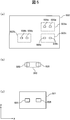
- the template matching process is a technique for detecting the position of the target object by searching for a position that matches the template image from a certain image using the template image.
- the mounting position is detected from the board image 502 of FIG. 5A obtained by photographing the range 306 of the board 107 with the camera 304 of FIG.
- the solders 506a, 506b, and 506c on the board 107 are photographed.
- the rectangles 503a, 503b, and 503c surrounding the solders 506a, 506b, and 506c are portions where the template images in FIG.
- FIG. 5B is a diagram showing the positional relationship between the solder 505 on the substrate 107 and the electronic component 360 at the time of mounting.
- FIG. 5C shows a template image 501 of the component mounting position when the electronic component is mounted in the positional relationship between the solder 505 and the electronic component 360 in FIG.
- step 601 the board image 502 is converted into a gray scale, and the luminance value of each pixel is calculated.
- the luminance value is defined as a degree indicating the brightness of a pixel indicated by a value from 0 (black) to 255 (white).
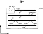
- step 602 as shown in FIG. 6, the template image 501 at the mounting position (image in which the solder 505 is arranged) is scanned along the arrow 511 of the board image 502, and the board image 502 and the template at each position are scanned.
- the degree of difference between the images 501 is calculated.
- the image dissimilarity is calculated by obtaining the sum of absolute values of differences between the luminance values of the pixels of the template image 501 and the substrate image 502. The lower the difference, the more similar the template image 501 and the substrate image 502 in the range where the template image 501 overlaps.
- the arrow 511 is shifted by one pixel in the Y-axis direction, and the dissimilarity is calculated while sequentially scanning along the arrows 512, 513, and 514.
- step 603 when the scanning of the template image 501 is completed to the lower right of the substrate image 502, the process proceeds to step 604.
- step 604 coordinates whose difference is equal to or less than the threshold are specified.
- step 605 the identified coordinates are recognized as mounting positions 503 a, 503 b, and 503 c and stored in the control unit 108.
- step 401 a process for detecting a mounting error from a target component mounting position and a component mounting position and obtaining a nozzle correction value performed in step 401, step 407, and step 408 will be described.
- acquisition of a mounting error will be described.
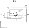
- An image 703 in FIG. 9 is an image after component mounting that is captured by the camera 304 in step 406.
- step 408 an image is captured in the image 703.
- the target component mounting position 701 (x, y) and the actual component mounting position 702 (x ′, y ′) are substituted into Expression 1-1 and Expression 1-2, and the actual component mounting position 702 is set as the origin.
- the mounting error ( ⁇ x, ⁇ y) is acquired.
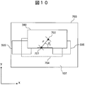
- FIG. 10 shows the mounting error using polar coordinates (r, ⁇ 1 ). In addition to xy coordinates, polar coordinates can also be used.
- FIG. 11 shows the state of the head actuator during component mounting. As shown by the nozzle 303 in FIG. 11, immediately after the operation of the component mounting apparatus, the tip of the nozzle 303 descends toward the target mounting position 1201, and ideally the component 305 is mounted at the position of the component 704.
- the nozzle 303 ′ is subjected to thermal deformation of the head and the beam, causing an inclination of the axis, and the nozzle tip is directed toward the mounting position 1202 that is separated from the target mounting position 1201 by the mounting error d.
- the component 305 is lowered and the component 305 is mounted at the position of the component 360 even in an ideal case.
- FIG. 12 shows the target mounting position 1201 and the mounting position 1202 in a plane.
- vibration occurs at the tip of the nozzle, resulting in blurring at the mounting location.
- Circular ranges 1203 and 1204 indicate the range of blur at the mounting location where the component 305 is actually mounted when the component 305 is mounted toward the target mounting position 1201 and the mounting position 1202. In other words, even if there is no mounting error d, if the component 305 is mounted toward the target mounting position 1201, it is actually mounted somewhere within the circular range 1203.
- the initial nozzle correction value obtained in step 401 can be used to fall within the allowable error range 1205.
- the range 1204 after thermal deformation does not always fall within the allowable error range 1205, it is necessary to update the nozzle correction value so that the range 1204 after thermal deformation overlaps the range 1203 immediately after the start of mounting. is there. Therefore, it is necessary to calculate the difference d between the target mounting position 1201 and the mounting position 1202 after thermal deformation, and add this to the nozzle correction value.
- the mounting position 1202 after thermal deformation is calculated as the average coordinates of the range 1204. Specifically, the average coordinate 1202 is calculated by taking the average of the mounting locations within the past one hour from the time of mounting. Then, a difference between the calculated average coordinates 1202 and the target mounting position 1201 is calculated and set as a new correction parameter.
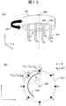
- FIG. 13 illustrates the relationship between the correction parameters of the nozzles accompanying the rotation of the rotor 301.
- FIG. 13A is a perspective view of the head actuator 103 in which eight nozzles 303P 1 to P 8 are arranged as an example.
- (b) show how the eight nozzles 303P 1 ⁇ P 8 is moving on a circle 1001 about the rotation center axis 350 with the rotation of the rotor 301.
- the nozzle 303 needs to supply and mount the component 305 at any position of P 1 to P 8 on the circle 1001.
- the nozzle is positioned using the nozzle correction value.
- the nozzle correction value ( ⁇ x p1 , ⁇ y p1 ) at the position P 1 before the rotation is set to the same angle as the angle at which the nozzle 303 is rotated in the direction of the arrow 1002. Convert using Equation 2.
- step 401 an initial nozzle correction value is obtained by the same method.
- a nozzle correction value is obtained for each of the nozzles 303 arranged in the head actuator 103.
- the correction parameter ( ⁇ x pn , ⁇ y pn ) calculated here is used as a target mounting position in addition to the component mounting location acquired in step 404 at the next mounting, thereby correcting the nozzle position.
- the first embodiment by reflecting the previous mounting error as a correction value at the next mounting, it is possible to cope with a change in mounting position due to a long-time operation and to achieve high-accuracy mounting.
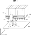
- Example 2 is an example of a component mounting apparatus when the head actuator 1301 shown in FIG. 14 is used, and this will be described below.
- nozzles 303 that move up and down in the Z-axis direction are mounted in a line.
- An actuator 1303 such as a linear motor is disposed on the camera beam 1302 disposed on the side surface of the head actuator 1301. This actuator 1303 moves the camera support 1304 that supports the camera 1305.
- the camera 1305 images the range 1306 on the substrate 107.
- FIG. 15 shows a flowchart of the second embodiment.
- step 1401 a component mounting test is performed using a test board before starting a component mounting operation, and an initial nozzle correction value is acquired and stored in the control unit 108.
- step 1402 the nozzle 303 holds the component 305 in the component supply unit 104.
- step 1403 the head actuator 1301 moves to the component mounting position.
- step 1404 the camera 1305 moves to a position where the nozzle 303 that performs the component mounting operation next can be observed, and images the mounted component 360.
- step 1405 the board 107 is imaged by the camera 1305, the component mounting position is acquired, and the initial nozzle correction value obtained in the process 1401 or the nozzle correction value obtained in the process 1409 is added to obtain the target component mounting position.
- step 1406 the component 305 is mounted at the target component mounting position acquired in step 1405.
- step 1407 the mounted component 360 is imaged by the camera 1305.
- step 1408 the control unit 108 detects the nozzle position coordinates at the time of mounting and the ideal nozzle position coordinates from the image obtained in step 1407, and calculates a mounting error.
- step 1409 the control unit 108 obtains the nozzle correction value at the next mounting by calculating the average value of the mounting error calculated in step 1408 and the mounting error for the most recent one hour, and sends it to the control unit 108.
- the stored nozzle correction value is updated.
- step 1412 it is determined whether or not all the boards to be mounted have been mounted. If all the boards to be mounted have been mounted, the mounting operation is terminated. If not, the process proceeds to step 1402. Thereafter, step 1402 to step 1412 are repeated to perform component mounting.
- the present invention can be applied to a head actuator in which nozzles are arranged in a line by making the camera 1305 movable.
- Example 3 is an example of a component mounting apparatus that can detect a nozzle lowering position before mounting a component.
- FIG. 16 is a perspective view of the head actuator 103 according to the third embodiment.
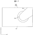
- FIG. 17 is a perspective view showing the state of the nozzle 303 and the substrate 107 immediately before mounting, taken by the camera 304 shown in FIG. 16.
- the nozzle 303 is provided with a mark 1502 that can be easily detected by the camera 304. ing.
- the mark 1502 attached to the nozzle is preferably a quadrangular shape or a material that reflects light so that it can be easily detected.
- the nozzle lowering position can be acquired before actual mounting, and therefore the nozzle lowering position is determined based on the nozzle lowering position acquired before the mounting operation. It is possible to adjust the target position.
Landscapes
- Engineering & Computer Science (AREA)
- Manufacturing & Machinery (AREA)
- Microelectronics & Electronic Packaging (AREA)
- Operations Research (AREA)
- Supply And Installment Of Electrical Components (AREA)
Abstract
La présente invention concerne un dispositif pour monter des composants électroniques et qui est pourvu : d'un actionneur de tête, qui est pourvu d'une buse permettant de monter un composant sur un substrat et d'un capteur d'image qui capture une image d'une surface du substrat, l'actionneur de tête étant mobile par rapport au substrat; et d'une unité de commande. L'unité de commande acquiert une erreur entre une position cible au niveau de laquelle le composant doit être monté sur le substrat, et l'emplacement de montage du composant acquis à partir de l'image de substrat capturée par le capteur d'image, et met à jour une valeur de correction de buse qui corrige la position de la buse en fonction de l'erreur. Par conséquent, même si le mécanisme du dispositif de montage de composant est déformé par la chaleur après un fonctionnement pendant une longue période, entraînant ainsi un changement de l'emplacement de montage pendant le travail de montage de composant, il est possible de toujours monter le composant au niveau de la position cible avec une précision élevée.
Priority Applications (1)
| Application Number | Priority Date | Filing Date | Title |
|---|---|---|---|
| PCT/JP2013/064375 WO2014188564A1 (fr) | 2013-05-23 | 2013-05-23 | Dispositif de montage de composant |
Applications Claiming Priority (1)
| Application Number | Priority Date | Filing Date | Title |
|---|---|---|---|
| PCT/JP2013/064375 WO2014188564A1 (fr) | 2013-05-23 | 2013-05-23 | Dispositif de montage de composant |
Publications (1)
| Publication Number | Publication Date |
|---|---|
| WO2014188564A1 true WO2014188564A1 (fr) | 2014-11-27 |
Family
ID=51933147
Family Applications (1)
| Application Number | Title | Priority Date | Filing Date |
|---|---|---|---|
| PCT/JP2013/064375 Ceased WO2014188564A1 (fr) | 2013-05-23 | 2013-05-23 | Dispositif de montage de composant |
Country Status (1)
| Country | Link |
|---|---|
| WO (1) | WO2014188564A1 (fr) |
Cited By (2)
| Publication number | Priority date | Publication date | Assignee | Title |
|---|---|---|---|---|
| CN105101664A (zh) * | 2014-05-22 | 2015-11-25 | 韩华泰科株式会社 | 部件贴装机的贴装位置数据调整方法及装置 |
| CN110199585A (zh) * | 2017-01-25 | 2019-09-03 | 株式会社富士 | 控制装置、安装装置及控制方法 |
Citations (7)
| Publication number | Priority date | Publication date | Assignee | Title |
|---|---|---|---|---|
| JPH05226889A (ja) * | 1992-02-17 | 1993-09-03 | Matsushita Electric Ind Co Ltd | 電子部品接続方法 |
| JP2003234600A (ja) * | 2002-02-08 | 2003-08-22 | Matsushita Electric Ind Co Ltd | 部品実装機の検査方法および装置 |
| JP2004079925A (ja) * | 2002-08-22 | 2004-03-11 | Juki Corp | マーク認識装置および方法 |
| JP2009081170A (ja) * | 2007-09-25 | 2009-04-16 | Yamaha Motor Co Ltd | 基板処理装置、管理コンピュータ装置、複数ステージ型表面実装機 |
| JP2009283646A (ja) * | 2008-05-22 | 2009-12-03 | Panasonic Corp | 部品実装機及び部品実装機の画像認識方法 |
| JP2011216614A (ja) * | 2010-03-31 | 2011-10-27 | Panasonic Corp | 部品実装装置および部品実装方法 |
| JP2011216616A (ja) * | 2010-03-31 | 2011-10-27 | Panasonic Corp | 部品実装装置および部品実装方法 |
-
2013
- 2013-05-23 WO PCT/JP2013/064375 patent/WO2014188564A1/fr not_active Ceased
Patent Citations (7)
| Publication number | Priority date | Publication date | Assignee | Title |
|---|---|---|---|---|
| JPH05226889A (ja) * | 1992-02-17 | 1993-09-03 | Matsushita Electric Ind Co Ltd | 電子部品接続方法 |
| JP2003234600A (ja) * | 2002-02-08 | 2003-08-22 | Matsushita Electric Ind Co Ltd | 部品実装機の検査方法および装置 |
| JP2004079925A (ja) * | 2002-08-22 | 2004-03-11 | Juki Corp | マーク認識装置および方法 |
| JP2009081170A (ja) * | 2007-09-25 | 2009-04-16 | Yamaha Motor Co Ltd | 基板処理装置、管理コンピュータ装置、複数ステージ型表面実装機 |
| JP2009283646A (ja) * | 2008-05-22 | 2009-12-03 | Panasonic Corp | 部品実装機及び部品実装機の画像認識方法 |
| JP2011216614A (ja) * | 2010-03-31 | 2011-10-27 | Panasonic Corp | 部品実装装置および部品実装方法 |
| JP2011216616A (ja) * | 2010-03-31 | 2011-10-27 | Panasonic Corp | 部品実装装置および部品実装方法 |
Cited By (5)
| Publication number | Priority date | Publication date | Assignee | Title |
|---|---|---|---|---|
| CN105101664A (zh) * | 2014-05-22 | 2015-11-25 | 韩华泰科株式会社 | 部件贴装机的贴装位置数据调整方法及装置 |
| CN105101664B (zh) * | 2014-05-22 | 2019-12-31 | 韩华精密机械株式会社 | 部件贴装机的贴装位置数据调整方法及装置 |
| CN110199585A (zh) * | 2017-01-25 | 2019-09-03 | 株式会社富士 | 控制装置、安装装置及控制方法 |
| EP3576511A4 (fr) * | 2017-01-25 | 2020-01-15 | Fuji Corporation | Dispositif et procédé de commande, et dispositif de montage |
| CN110199585B (zh) * | 2017-01-25 | 2021-06-15 | 株式会社富士 | 控制装置、安装装置及控制方法 |
Similar Documents
| Publication | Publication Date | Title |
|---|---|---|
| CN103079746A (zh) | 激光加工装置及基板位置检测方法 | |
| CN100407888C (zh) | 部件安装方法 | |
| KR102034481B1 (ko) | 전자 부품의 실장 방법 및 실장 장치 | |
| JPH118497A (ja) | 電子部品実装方法及び装置 | |
| US20090252400A1 (en) | Method for mounting electronic component | |
| JP3744251B2 (ja) | 電子部品実装方法 | |
| WO2012144282A1 (fr) | Machine de montage de pièce électrique et procédé de fabrication de circuit électrique | |
| JP6534447B2 (ja) | 部品実装装置 | |
| WO2014174598A1 (fr) | Dispositif de montage de composant, tête de montage, et dispositif de commande | |
| JP6190229B2 (ja) | 部品実装装置 | |
| JP5776089B2 (ja) | 部品実装装置 | |
| JP6411663B2 (ja) | 部品実装装置 | |
| JP4587877B2 (ja) | 部品実装装置 | |
| US8701275B2 (en) | Surface mounting apparatus | |
| JP5507378B2 (ja) | 電子部品実装装置 | |
| JP6849815B2 (ja) | 部品実装装置、撮影方法、実装順序の決定方法 | |
| JP5318334B2 (ja) | 対象物の位置検出方法及び装置 | |
| JP4927776B2 (ja) | 部品実装方法 | |
| JP2010147401A (ja) | 電子部品装着装置及び画像歪補正方法 | |
| WO2014188564A1 (fr) | Dispositif de montage de composant | |
| CN108605432A (zh) | 表面安装机、识别误差校正方法 | |
| JP5241530B2 (ja) | 電子部品実装装置および搭載方法 | |
| JP2019012784A (ja) | 部品保持具の偏心補正方法 | |
| JP7581564B2 (ja) | 部品実装装置 | |
| JP7780739B2 (ja) | 部品装着装置、補正データの生成方法および部品装着システム |
Legal Events
| Date | Code | Title | Description |
|---|---|---|---|
| 121 | Ep: the epo has been informed by wipo that ep was designated in this application |
Ref document number: 13885080 Country of ref document: EP Kind code of ref document: A1 |
|
| NENP | Non-entry into the national phase |
Ref country code: DE |
|
| 122 | Ep: pct application non-entry in european phase |
Ref document number: 13885080 Country of ref document: EP Kind code of ref document: A1 |
|
| NENP | Non-entry into the national phase |
Ref country code: JP |