WO2014188595A1 - 内燃機関の制御装置 - Google Patents
内燃機関の制御装置 Download PDFInfo
- Publication number
- WO2014188595A1 WO2014188595A1 PCT/JP2013/064514 JP2013064514W WO2014188595A1 WO 2014188595 A1 WO2014188595 A1 WO 2014188595A1 JP 2013064514 W JP2013064514 W JP 2013064514W WO 2014188595 A1 WO2014188595 A1 WO 2014188595A1
- Authority
- WO
- WIPO (PCT)
- Prior art keywords
- air
- fuel ratio
- target
- torque
- amount
- Prior art date
- Legal status (The legal status is an assumption and is not a legal conclusion. Google has not performed a legal analysis and makes no representation as to the accuracy of the status listed.)
- Ceased
Links
Images





Classifications
-
- F—MECHANICAL ENGINEERING; LIGHTING; HEATING; WEAPONS; BLASTING
- F02—COMBUSTION ENGINES; HOT-GAS OR COMBUSTION-PRODUCT ENGINE PLANTS
- F02D—CONTROLLING COMBUSTION ENGINES
- F02D41/00—Electrical control of supply of combustible mixture or its constituents
- F02D41/24—Electrical control of supply of combustible mixture or its constituents characterised by the use of digital means
- F02D41/26—Electrical control of supply of combustible mixture or its constituents characterised by the use of digital means using computer, e.g. microprocessor
-
- F—MECHANICAL ENGINEERING; LIGHTING; HEATING; WEAPONS; BLASTING
- F02—COMBUSTION ENGINES; HOT-GAS OR COMBUSTION-PRODUCT ENGINE PLANTS
- F02P—IGNITION, OTHER THAN COMPRESSION IGNITION, FOR INTERNAL-COMBUSTION ENGINES; TESTING OF IGNITION TIMING IN COMPRESSION-IGNITION ENGINES
- F02P5/00—Advancing or retarding ignition; Control therefor
- F02P5/04—Advancing or retarding ignition; Control therefor automatically, as a function of the working conditions of the engine or vehicle or of the atmospheric conditions
- F02P5/145—Advancing or retarding ignition; Control therefor automatically, as a function of the working conditions of the engine or vehicle or of the atmospheric conditions using electrical means
- F02P5/15—Digital data processing
- F02P5/1502—Digital data processing using one central computing unit
- F02P5/1504—Digital data processing using one central computing unit with particular means during a transient phase, e.g. acceleration, deceleration, gear change
-
- F—MECHANICAL ENGINEERING; LIGHTING; HEATING; WEAPONS; BLASTING
- F02—COMBUSTION ENGINES; HOT-GAS OR COMBUSTION-PRODUCT ENGINE PLANTS
- F02D—CONTROLLING COMBUSTION ENGINES
- F02D37/00—Non-electrical conjoint control of two or more functions of engines, not otherwise provided for
- F02D37/02—Non-electrical conjoint control of two or more functions of engines, not otherwise provided for one of the functions being ignition
-
- F—MECHANICAL ENGINEERING; LIGHTING; HEATING; WEAPONS; BLASTING
- F02—COMBUSTION ENGINES; HOT-GAS OR COMBUSTION-PRODUCT ENGINE PLANTS
- F02D—CONTROLLING COMBUSTION ENGINES
- F02D41/00—Electrical control of supply of combustible mixture or its constituents
- F02D41/0002—Controlling intake air
-
- F—MECHANICAL ENGINEERING; LIGHTING; HEATING; WEAPONS; BLASTING
- F02—COMBUSTION ENGINES; HOT-GAS OR COMBUSTION-PRODUCT ENGINE PLANTS
- F02D—CONTROLLING COMBUSTION ENGINES
- F02D41/00—Electrical control of supply of combustible mixture or its constituents
- F02D41/30—Controlling fuel injection
- F02D41/3011—Controlling fuel injection according to or using specific or several modes of combustion
- F02D41/3064—Controlling fuel injection according to or using specific or several modes of combustion with special control during transition between modes
- F02D41/307—Controlling fuel injection according to or using specific or several modes of combustion with special control during transition between modes to avoid torque shocks
-
- F—MECHANICAL ENGINEERING; LIGHTING; HEATING; WEAPONS; BLASTING
- F02—COMBUSTION ENGINES; HOT-GAS OR COMBUSTION-PRODUCT ENGINE PLANTS
- F02D—CONTROLLING COMBUSTION ENGINES
- F02D41/00—Electrical control of supply of combustible mixture or its constituents
- F02D41/30—Controlling fuel injection
- F02D41/32—Controlling fuel injection of the low pressure type
- F02D41/34—Controlling fuel injection of the low pressure type with means for controlling injection timing or duration
-
- F—MECHANICAL ENGINEERING; LIGHTING; HEATING; WEAPONS; BLASTING
- F02—COMBUSTION ENGINES; HOT-GAS OR COMBUSTION-PRODUCT ENGINE PLANTS
- F02D—CONTROLLING COMBUSTION ENGINES
- F02D11/00—Arrangements for, or adaptations to, non-automatic engine control initiation means, e.g. operator initiated
- F02D11/06—Arrangements for, or adaptations to, non-automatic engine control initiation means, e.g. operator initiated characterised by non-mechanical control linkages, e.g. fluid control linkages or by control linkages with power drive or assistance
- F02D11/10—Arrangements for, or adaptations to, non-automatic engine control initiation means, e.g. operator initiated characterised by non-mechanical control linkages, e.g. fluid control linkages or by control linkages with power drive or assistance of the electric type
- F02D11/105—Arrangements for, or adaptations to, non-automatic engine control initiation means, e.g. operator initiated characterised by non-mechanical control linkages, e.g. fluid control linkages or by control linkages with power drive or assistance of the electric type characterised by the function converting demand to actuation, e.g. a map indicating relations between an accelerator pedal position and throttle valve opening or target engine torque
-
- F—MECHANICAL ENGINEERING; LIGHTING; HEATING; WEAPONS; BLASTING
- F02—COMBUSTION ENGINES; HOT-GAS OR COMBUSTION-PRODUCT ENGINE PLANTS
- F02D—CONTROLLING COMBUSTION ENGINES
- F02D13/00—Controlling the engine output power by varying inlet or exhaust valve operating characteristics, e.g. timing
- F02D13/02—Controlling the engine output power by varying inlet or exhaust valve operating characteristics, e.g. timing during engine operation
- F02D13/0223—Variable control of the intake valves only
- F02D13/0234—Variable control of the intake valves only changing the valve timing only
-
- F—MECHANICAL ENGINEERING; LIGHTING; HEATING; WEAPONS; BLASTING
- F02—COMBUSTION ENGINES; HOT-GAS OR COMBUSTION-PRODUCT ENGINE PLANTS
- F02D—CONTROLLING COMBUSTION ENGINES
- F02D41/00—Electrical control of supply of combustible mixture or its constituents
- F02D41/0002—Controlling intake air
- F02D2041/001—Controlling intake air for engines with variable valve actuation
-
- F—MECHANICAL ENGINEERING; LIGHTING; HEATING; WEAPONS; BLASTING
- F02—COMBUSTION ENGINES; HOT-GAS OR COMBUSTION-PRODUCT ENGINE PLANTS
- F02D—CONTROLLING COMBUSTION ENGINES
- F02D2250/00—Engine control related to specific problems or objectives
- F02D2250/18—Control of the engine output torque
- F02D2250/21—Control of the engine output torque during a transition between engine operation modes or states
-
- F—MECHANICAL ENGINEERING; LIGHTING; HEATING; WEAPONS; BLASTING
- F02—COMBUSTION ENGINES; HOT-GAS OR COMBUSTION-PRODUCT ENGINE PLANTS
- F02D—CONTROLLING COMBUSTION ENGINES
- F02D23/00—Controlling engines characterised by their being supercharged
-
- F—MECHANICAL ENGINEERING; LIGHTING; HEATING; WEAPONS; BLASTING
- F02—COMBUSTION ENGINES; HOT-GAS OR COMBUSTION-PRODUCT ENGINE PLANTS
- F02D—CONTROLLING COMBUSTION ENGINES
- F02D41/00—Electrical control of supply of combustible mixture or its constituents
- F02D41/0002—Controlling intake air
- F02D41/0007—Controlling intake air for control of turbo-charged or super-charged engines
-
- F—MECHANICAL ENGINEERING; LIGHTING; HEATING; WEAPONS; BLASTING
- F02—COMBUSTION ENGINES; HOT-GAS OR COMBUSTION-PRODUCT ENGINE PLANTS
- F02D—CONTROLLING COMBUSTION ENGINES
- F02D41/00—Electrical control of supply of combustible mixture or its constituents
- F02D41/30—Controlling fuel injection
- F02D41/3011—Controlling fuel injection according to or using specific or several modes of combustion
- F02D41/3017—Controlling fuel injection according to or using specific or several modes of combustion characterised by the mode(s) being used
- F02D41/3023—Controlling fuel injection according to or using specific or several modes of combustion characterised by the mode(s) being used a mode being the stratified charge spark-ignited mode
- F02D41/3029—Controlling fuel injection according to or using specific or several modes of combustion characterised by the mode(s) being used a mode being the stratified charge spark-ignited mode further comprising a homogeneous charge spark-ignited mode
-
- Y—GENERAL TAGGING OF NEW TECHNOLOGICAL DEVELOPMENTS; GENERAL TAGGING OF CROSS-SECTIONAL TECHNOLOGIES SPANNING OVER SEVERAL SECTIONS OF THE IPC; TECHNICAL SUBJECTS COVERED BY FORMER USPC CROSS-REFERENCE ART COLLECTIONS [XRACs] AND DIGESTS
- Y02—TECHNOLOGIES OR APPLICATIONS FOR MITIGATION OR ADAPTATION AGAINST CLIMATE CHANGE
- Y02T—CLIMATE CHANGE MITIGATION TECHNOLOGIES RELATED TO TRANSPORTATION
- Y02T10/00—Road transport of goods or passengers
- Y02T10/10—Internal combustion engine [ICE] based vehicles
- Y02T10/40—Engine management systems
Definitions
- the present invention relates to a control device that integrally controls an air amount, a fuel supply amount, and an ignition timing of an internal combustion engine configured such that an air-fuel ratio used for operation can be switched between at least two air-fuel ratios.
- Japanese Patent Application Laid-Open No. 11-22609 discloses a technique relating to combustion system switching control in an internal combustion engine capable of switching the combustion system of an internal combustion engine from stratified combustion to homogeneous combustion or from homogeneous combustion to stratified combustion (hereinafter referred to as prior art) Is disclosed. Since the air-fuel ratio in stratified combustion is leaner than the air-fuel ratio in homogeneous combustion, switching of the combustion method is accompanied by switching of the air-fuel ratio. As a method of switching the air-fuel ratio, a method of gradually changing the air-fuel ratio so as not to generate a torque step is well known.
- the target air amount is switched stepwise before the target equivalent ratio is switched stepwise. Specifically, only the target air amount is increased stepwise to increase the air amount in advance, and the target equivalence ratio is decreased stepwise when the actual air amount reaches the target air amount. That is, the target equivalent ratio before switching of the combustion method is maintained while the air amount increases after the target air amount.
- the fuel amount is determined based on the target equivalent ratio before switching the combustion method, the fuel amount becomes excessive than the amount necessary for keeping the torque constant. For this reason, in the above prior art, an increase in the torque before switching the combustion system is avoided by correcting the excess amount of the fuel with the retard of the ignition timing.
- misfire in the retarded ignition timing. Misfires lead to poor drivability and exhaust performance. Misfire can be prevented by limiting the retard of the ignition timing, but an increase in torque due to an excessive amount of fuel cannot be avoided.
- the present invention has been made in view of the above-described problems, and in an internal combustion engine configured to be able to switch the air-fuel ratio used for operation between at least two air-fuel ratios, the air-fuel ratio is switched without causing torque fluctuations. This is the issue.
- the present invention can be applied to the configuration of a control device for an internal combustion engine.
- the outline of the control apparatus for an internal combustion engine according to the present invention will be described below.
- the present invention can be applied to the procedure of the control method of the internal combustion engine, and can also be applied to an algorithm of a program executed by the control device. .
- the control device controls an internal combustion engine that includes three types of actuators and is configured to be able to select an operation with a first air-fuel ratio and an operation with a second air-fuel ratio that is leaner than the first air-fuel ratio.
- the three types of actuators are a first actuator that changes the amount of air, a second actuator that supplies fuel into the cylinder, and a third actuator that ignites the mixture in the cylinder.
- the first actuator includes, for example, a variable valve timing mechanism that changes the valve timing of a throttle and an intake valve, and if the internal combustion engine is a supercharged engine, the supercharging that changes the supercharging characteristics of the supercharger.
- a variable characteristic actuator specifically, a variable nozzle, a waste gate valve, and the like are included in the first actuator.
- the second actuator is an injector that injects fuel, and includes, for example, a port injector that injects fuel into the intake port and an in-cylinder injector that directly injects fuel into the cylinder.
- the third actuator is an ignition device.
- the control device according to the present invention integrally controls the air amount, fuel supply amount, and ignition timing of the internal combustion engine by cooperative operation of these three types of actuators.
- the control device can be embodied by a computer. More specifically, the control device according to the present invention is configured by a computer including a memory storing a program describing processing for realizing various functions and a processor that reads and executes the program from the memory. Can do.
- the functions of the control device according to the present invention include a required torque receiving function, a target air-fuel ratio switching function, a target air as functions for determining the target air amount and target air-fuel ratio used for the cooperative operation of the three types of actuators. An amount calculation function and a virtual air-fuel ratio change function are included. *
- the required torque reception function receives the required torque for the internal combustion engine.
- the required torque is calculated based on a signal responsive to the accelerator pedal opening operated by the driver.
- a required torque that decreases according to the speed at which the driver closes the accelerator pedal is obtained.
- a required torque that increases according to the speed at which the driver opens the accelerator pedal is obtained.
- the target air amount calculation function the target air amount for achieving the required torque is calculated backward from the required torque.
- a parameter that gives the conversion efficiency of the air amount into torque is used.
- the virtual air-fuel ratio is a parameter corresponding to the air-fuel ratio and is one of parameters used for calculating the target air amount.
- the value of the virtual air / fuel ratio is variable and is changed by the virtual air / fuel ratio changing function.
- the virtual air-fuel ratio changing function the virtual air-fuel ratio is changed from the first air-fuel ratio to the second air-fuel ratio in response to the satisfaction of the condition for switching the operation mode from the first air-fuel ratio operation to the second air-fuel ratio operation. Changed to fuel ratio. If the value of the required torque is the same, the target air amount decreases as the virtual air-fuel ratio becomes rich, and the target air amount increases as the virtual air-fuel ratio becomes lean.
- the target air-fuel ratio switching function after the virtual air-fuel ratio is changed from the first air-fuel ratio to the second air-fuel ratio, the target air-fuel ratio is intermediate between the first air-fuel ratio and the first air-fuel ratio.
- the air-fuel ratio is switched to the third air-fuel ratio, and immediately thereafter, the third air-fuel ratio is switched to the second air-fuel ratio. That is, the target air-fuel ratio is not directly switched from the first air-fuel ratio to the second air-fuel ratio, but is switched from the third air-fuel ratio to the second air-fuel ratio after a temporary switch to the intermediate third air-fuel ratio.
- the intermediate air-fuel ratio here means an air-fuel ratio that is leaner than the first air-fuel ratio and richer than the second air-fuel ratio, and the median value between the first air-fuel ratio and the second air-fuel ratio is It is not limited.
- the specific timing for switching the target air-fuel ratio from the first air-fuel ratio to the third air-fuel ratio is such that the air amount estimated from the operation amount of the first actuator is such that the required torque can be achieved under the third air-fuel ratio. It is preferable that the point is reached. However, when the amount of air that can achieve the required torque under the third air-fuel ratio is less than the minimum amount of air that does not cause misfire, the amount of air estimated from the operation amount of the first actuator exceeds the minimum amount of air. Therefore, it is more preferable to switch the target air-fuel ratio from the first air-fuel ratio to the third air-fuel ratio.
- the target air-fuel ratio may be switched from the first air-fuel ratio to the third air-fuel ratio.
- the switching condition is that the shortage of the torque that can be achieved under the third air-fuel ratio is smaller than the excess of the torque that can be achieved under the first air-fuel ratio.
- the specific timing for switching the target air-fuel ratio from the third air-fuel ratio to the second air-fuel ratio is preferably when the difference between the target air amount and the estimated air amount is equal to or less than a threshold value.
- the target air-fuel ratio may be switched from the third air-fuel ratio to the second air-fuel ratio when a predetermined time has elapsed since the target air-fuel ratio was switched from the first air-fuel ratio to the third air-fuel ratio.
- the target air-fuel ratio may be switched from the third air-fuel ratio to the second air-fuel ratio when a predetermined time has elapsed since the virtual air-fuel ratio was changed from the first air-fuel ratio to the second air-fuel ratio.
- the control device cooperatively operates the three types of actuators based on the target air amount and the target air-fuel ratio determined by the above processing.
- the functions of the control device according to the present invention include a first actuator control function, a second actuator control function, and a third actuator control function as functions for cooperative operation based on the target air amount and the target air-fuel ratio. included.
- the operation amount of the first actuator is determined based on the target air amount. Then, the first actuator is operated according to the determined operation amount. The actual air amount changes so as to follow the target air amount by operating the first actuator.
- the fuel supply amount is determined based on the target air-fuel ratio. Then, the second actuator is operated according to the determined fuel supply amount.
- the ignition timing for achieving the required torque is determined based on the torque estimated from the operation amount of the first actuator and the target air-fuel ratio and the required torque. Then, the third actuator is operated according to the determined ignition timing.
- the actual air amount can be estimated from the operation amount of the first actuator, and the torque can be estimated from the estimated air amount and the target air-fuel ratio.
- the operation of the third actuator is performed so that the excess of the estimated torque with respect to the required torque is corrected by the ignition timing.
- control device of the present invention by providing the above-described function, torque fluctuation does not occur from the operation with the first air-fuel ratio to the operation with the second air-fuel ratio leaner than the first air-fuel ratio.
- the operation mode of the internal combustion engine can be switched.
- Embodiment 1 of the present invention will be described below with reference to the drawings.
- An internal combustion engine (hereinafter referred to as an engine) to be controlled in the present embodiment is a spark ignition type four-cycle reciprocating engine.
- this engine is a so-called lean burn engine, and as an engine operation mode, a stoichiometric mode (first operation mode) in which operation is performed with a stoichiometric air-fuel ratio and a lean mode in which operation is performed with an air-fuel ratio leaner than the stoichiometric air-fuel ratio. (Second operation mode) can be selected.
- the ECU Electronic Control Unit installed in the vehicle controls the operation of the engine by operating various actuators provided in the engine.
- the actuator operated by the ECU includes a throttle that is a first actuator that changes the air amount, a variable valve timing mechanism (hereinafter referred to as VVT), an injector that is a second actuator that supplies fuel into the cylinder, and an air-fuel mixture in the cylinder. Includes an ignition device which is a third actuator for igniting the motor.
- VVT is provided for the intake valve, and the injector is provided for the intake port.
- the ECU operates these actuators to control the operation of the engine.
- the engine control by the ECU includes switching of the operation mode from the stoichiometric mode to the lean mode, or from the lean mode to the stoichiometric mode.
- FIG. 1 is a block diagram showing the logic of the ECU according to the present embodiment.
- the ECU includes an engine controller 100 and a powertrain manager 200.
- the engine controller 100 is a control device that directly controls the engine, and corresponds to the control device according to the present invention.
- the powertrain manager 200 is a control device that performs integrated control of the entire drive system including an engine, an electronically controlled automatic transmission, and vehicle control devices such as VSC and TRC.
- the engine controller 100 is configured to control the operation of the engine based on a signal received from the powertrain manager 200.
- the engine controller 100 and the powertrain manager 200 are both realized by software. Specifically, the functions of the engine controller 100 and the powertrain manager 200 are realized in the ECU by reading a program stored in the memory and executing the program by the processor.
- the engine controller 100 and the powertrain manager 200 can be assigned to different cores or core groups.
- the arithmetic unit 202 calculates the requested first torque and transmits it to the engine controller 100.
- the required first torque is indicated as “TQ1r”.
- the first torque is a kind of torque that does not have high responsiveness required for the engine and that may be realized in the near future if not immediately.
- the requested first torque is a requested value of the first torque that the powertrain manager 200 requests for the engine, and corresponds to the requested torque in the present invention.
- a signal output in response to the opening of the accelerator pedal is input to the arithmetic unit 202 from an accelerator position sensor (not shown).
- the required first torque is calculated based on the signal.
- the requested first torque is a shaft torque.
- the arithmetic unit 204 calculates the requested second torque and transmits it to the engine controller 100.
- the required second torque is indicated as “TQ2r”.
- the second torque is a type of torque that has higher urgency or priority than the first torque and requires high responsiveness to the engine, that is, a type of torque that is required to be realized immediately.
- the responsiveness mentioned here means responsiveness when the torque is temporarily reduced.
- the requested second torque is a requested value of the second torque that the powertrain manager 200 requests from the engine.
- the required second torque calculated by the arithmetic unit 204 is required for the shift control of the electronically controlled automatic transmission, the torque required for the traction control, and the side slip prevention control. Torque required from the vehicle control system, such as torque, is included.
- the first torque is a torque required for the engine constantly or over a long period of time
- the second torque is a torque required for the engine suddenly or for a short period of time.
- the arithmetic unit 204 outputs an effective value corresponding to the magnitude of the torque to be realized only when an event that actually requires such torque occurs, and while such an event does not occur Outputs an invalid value.
- the invalid value is set to a value larger than the maximum shaft torque that can be output by the engine.
- the arithmetic unit 206 calculates the gear ratio of the automatic transmission and transmits a signal for instructing the gear ratio to a transmission controller (not shown).
- the transmission controller is realized as one function of the ECU, like the powertrain manager 200 and the engine controller 100.
- a flag signal is input from the engine controller 100 to the arithmetic unit 206. In the figure, the flag signal is described as “FLG”.
- the flag signal is a signal indicating that the operation mode is being switched. While the flag signal is on, the arithmetic unit 206 fixes the gear ratio of the automatic transmission. That is, while the operation mode is being switched, the change of the gear ratio by the automatic transmission is prohibited so that the operation state of the engine does not change greatly.
- the arithmetic unit 208 transmits to the engine controller 100 a stop signal instructing to stop the operation mode switching in response to the predetermined condition being satisfied.
- the stop signal is described as “Stop”.
- the predetermined condition is that a request to greatly change the operating state of the engine is issued from the powertrain manager 200. For example, when changing the gear ratio of the automatic transmission or when a special request regarding the ignition timing or fuel injection amount is issued to the engine for warming up the catalyst, a stop signal is output from the arithmetic unit 208. Is done.
- Interfaces 101, 102, 103, and 104 are set between the engine controller 100 and the powertrain manager 200.
- the interface 101 corresponds to the required torque receiving means in the present invention, and the required first torque is transferred at the interface 101.
- a stop signal is transferred in the interface 102.
- the interface 103 exchanges flag signals. Then, the requested second torque is transferred at the interface 104.
- the throttle 2 and VVT 8 as the first actuator
- the injector 4 as the second actuator
- the functions related to the cooperative operation of the ignition device 6 that is the third actuator are represented by blocks.
- An arithmetic unit is assigned to each of these blocks.
- Programs corresponding to the respective blocks are prepared in the ECU, and the functions of the respective arithmetic units are realized in the ECU by being executed by the processor.
- the arithmetic unit which comprises the engine controller 100 can be distributed and allocated to several cores.
- the engine controller 100 is roughly composed of three large arithmetic units 120, 140, and 160.
- the large arithmetic unit 120 calculates values of various control parameters for the engine.
- the control parameters include target values for various control amounts for the engine.
- the target values include those calculated based on the request value transmitted from the powertrain manager 200 and those calculated inside the large arithmetic unit 120 based on the information related to the operating state of the engine. .
- the required value is a control amount value that is unilaterally requested from the powertrain manager 200 without considering the engine state, whereas the target value is set based on a feasible range determined by the engine state. Is the value of the controlled variable.
- the large arithmetic unit 120 includes four arithmetic units 122, 124, 126, and 128.
- the arithmetic unit 122 calculates a target air-fuel ratio, a virtual air-fuel ratio, a switching target efficiency, and a switching target second torque as control parameters for the engine.
- the target air-fuel ratio is expressed as “AFt”
- the virtual air-fuel ratio is expressed as “AFh”
- the target efficiency for switching is expressed as “ ⁇ tc”
- the target second torque for switching is expressed as “TQ2c”.
- the target air-fuel ratio is a target value of the air-fuel ratio realized in the engine, and is used for calculating the fuel injection amount.
- the virtual air-fuel ratio is a parameter that gives a conversion efficiency of torque into an air amount, and is used for calculating a target air amount.
- the target efficiency for switching is a target value of the ignition timing efficiency for switching the operation mode, and is used for calculating the target air amount.
- the ignition timing efficiency means the ratio of the torque that is actually output with respect to the torque that can be output when the ignition timing is the optimal ignition timing, and is 1 that is the maximum value when the ignition timing is the optimal ignition timing.
- the optimum ignition timing basically means MBT (Minimum Advance Advance for Best Torque), and when the trace knock ignition timing is set, it is more delayed than the MBT and the trace knock ignition timing. It means a certain ignition timing.
- the target second torque for switching is a target value of the second torque for switching the operation mode, and is used for switching calculation of ignition timing efficiency when the operation mode is switched. The operation mode is switched by a combination of these control parameter values calculated by the arithmetic unit 122. The relationship between the content of processing performed in the arithmetic unit 122 and switching of the operation mode will be described in detail later.
- various information related to the operating state of the engine such as the engine speed, is input in addition to the requested first torque, the requested second torque, and the stop signal given from the powertrain manager 200.
- the information used to determine the timing for switching the operation mode is the requested first torque.
- the requested second torque and the stop signal are used as information for determining whether switching of the operation mode is permitted or prohibited.
- the arithmetic unit 122 does not execute the process related to the switching of the operation mode. Further, the arithmetic unit 122 transmits the above-described flag signal to the powertrain manager 200 during the switching of the operation mode, that is, while the calculation process for switching the operation mode is being executed.
- the arithmetic unit 124 is classified as the first torque among the torques required to maintain the current engine operating state or to realize a predetermined operating state as a control parameter for the engine. Calculate the torque.
- the torque calculated by the arithmetic unit 124 is referred to as other first torque.
- the other first torque is indicated as “TQ1etc”.
- the first torque includes a torque within a range of fluctuations that can be achieved only by controlling the air amount, among torques necessary for maintaining a predetermined idle speed when the engine is in an idle state.
- the arithmetic unit 124 outputs a valid value only when such torque is actually needed, and calculates an invalid value while such torque is not needed.
- the invalid value is set to a value larger than the maximum indicated torque that the engine can output.
- the arithmetic unit 126 is classified as a second torque among the torques required to maintain the current engine operating state or to realize a predetermined operating state as a control parameter for the engine. Calculate the torque.
- the torque calculated by the arithmetic unit 126 is referred to as other second torque.
- the other second torque is described as “TQ2etc”.
- the other second torque includes a torque that needs to be controlled in the ignition timing in order to achieve the torque among the torques necessary to maintain a predetermined idle speed when the engine is in an idle state.
- the arithmetic unit 126 outputs a valid value only when such torque is actually needed, and calculates an invalid value while such torque is not needed.
- the invalid value is set to a value larger than the maximum indicated torque that the engine can output.
- the arithmetic unit 128 calculates the ignition timing efficiency required to maintain the current engine operating state or to realize a predetermined operating state as a control parameter for the engine.
- the ignition timing efficiency calculated by the arithmetic unit 128 is referred to as other efficiency.
- other efficiency is indicated as “ ⁇ etc”.
- the other efficiency includes the ignition timing efficiency necessary for warming up the exhaust gas purification catalyst when the engine is started. The lower the ignition timing efficiency, the less energy that is converted into torque from the energy generated by the combustion of the fuel, and that much energy is discharged along with the exhaust gas into the exhaust passage to warm up the exhaust purification catalyst. Will be used. While it is not necessary to realize such efficiency, the efficiency value output from the arithmetic unit 128 is held at 1 which is the maximum value.
- the required first torque, other first torque, target air-fuel ratio, virtual air-fuel ratio, switching target efficiency, other efficiency, required second torque, switching target second Torque and other second torque are output. These control parameters are input to the large arithmetic unit 140.
- the requested first torque and the requested second torque provided from the powertrain manager 200 are shaft torques, but the large arithmetic unit 120 corrects them to the indicated torque.
- the required torque is corrected to the indicated torque by adding or subtracting the friction torque, accessory driving torque, and pump loss to the required torque. Note that the torque such as the switching target second torque calculated within the large arithmetic unit 120 is calculated as the indicated torque.
- the large arithmetic unit 140 will be described. As described above, various engine control parameters are sent from the large arithmetic unit 120. Of these, the requested first torque and the other first torque are requests for control amounts belonging to the same category, and cannot be established at the same time. Similarly, the requested second torque, the other second torque, and the switching target second torque are requests for control amounts belonging to the same category and cannot be established at the same time. Similarly, the target efficiency for switching and the other efficiency are requests for control amounts belonging to the same category, and cannot be established at the same time. For this reason, a process called arbitration is required for each control amount category.
- Arbitration here is calculation processing for obtaining one numerical value from a plurality of numerical values, such as maximum value selection, minimum value selection, averaging, or superposition, for example, and appropriately combining a plurality of types of calculation processing It can also be.
- the large arithmetic unit 140 includes three arithmetic units 142, 144, and 146.
- the arithmetic unit 142 is configured to mediate the first torque.
- the requested first torque and the other first torque are input to the arithmetic unit 142.
- the arithmetic unit 142 arbitrates them and outputs the arbitrated torque as the finally determined target first torque.
- the finally determined target first torque is indicated as “TQ1t”.
- TQ1t the finally determined target first torque.
- the arithmetic unit 144 is configured to adjust the ignition timing efficiency.
- the target efficiency for switching and other efficiency are input to the arithmetic unit 144.
- the arithmetic unit 144 arbitrates them and outputs the arbitrated efficiency as the finally determined target efficiency.
- the finally determined target efficiency is expressed as “ ⁇ t”.
- As an arbitration method in the arithmetic unit 144 minimum value selection is used. From the viewpoint of fuel efficiency, it is preferable that the ignition timing efficiency is 1, which is the maximum value. Therefore, unless there is a special event, the target efficiency for switching calculated by the arithmetic unit 122 and the other efficiencies calculated by the arithmetic unit 128 are held at 1 which is the maximum value. Therefore, the target efficiency value output from the arithmetic unit 144 is basically 1, and a value smaller than 1 is selected only when some event occurs.
- the arithmetic unit 146 is configured to mediate the second torque.
- the requested second torque, the other second torque, and the switching target second torque are input to the arithmetic unit 146.
- the arithmetic unit 146 arbitrates them and outputs the arbitrated torque as the finally determined target second torque.
- the finally determined target second torque is described as “TQ2t”.
- minimum value selection is used as an arbitration method in the arithmetic unit 146.
- the second torque is basically an invalid value including the target second torque for switching, and is switched to an effective value indicating the magnitude of the torque to be realized only when a specific event occurs. Therefore, the target second torque output from the arithmetic unit 146 is basically also an invalid value, and the valid value is selected only when some event occurs.
- the large arithmetic unit 140 configured as described above outputs the target first torque, target efficiency, virtual air-fuel ratio, target air-fuel ratio, and target second torque. These control parameters are input to the large arithmetic unit 160.
- the large arithmetic unit 160 corresponds to an inverse model of the engine, and is composed of a plurality of models represented by maps and functions.
- the operation amount of each actuator 2, 4, 6, 8 for cooperative operation is calculated by the large arithmetic unit 160.
- both the target first torque and the target second torque are treated as target values of torque for the engine.
- the target second torque has priority over the target first torque.
- the target second torque is achieved when the target second torque is an effective value, and the target first torque is achieved when the target second torque is an invalid value.
- the amount of operation of each actuator 2, 4, 6, 8 is calculated.
- the operation amount is calculated so that the target air-fuel ratio and the target efficiency are achieved simultaneously with the target torque. That is, in the control device according to the present embodiment, torque, efficiency, and air-fuel ratio are used as engine control amounts, and air amount control, ignition timing control, and fuel injection amount are based on target values of these three types of control amounts. Control is implemented.
- the large arithmetic unit 160 includes a plurality of arithmetic units 162, 164, 166, 168, 170, 172, 174, 176, 178.
- arithmetic units 162, 164, 166, 178 those relating to air amount control are arithmetic units 162, 164, 166, 178, and those relating to ignition timing control are arithmetic units 168, 170, 172, which are related to fuel injection amount control. What is to be done is the arithmetic units 174, 176.
- the function of each arithmetic unit will be described in order from the arithmetic unit related to the air amount control.
- the calculation unit 162 receives the target first torque, the target efficiency, and the virtual air-fuel ratio.
- the arithmetic unit 162 corresponds to the target air amount calculation means in the present invention, and uses the target efficiency and the virtual air-fuel ratio to back-calculate the target air amount for achieving the target first torque from the target first torque.
- the target efficiency and the virtual air-fuel ratio are used as parameters that give the conversion efficiency of the air amount into torque.
- the air amount is the amount of air sucked into the cylinder, and the filling efficiency or load factor obtained by making it dimensionless is within the same range of the air amount in the present invention.
- the arithmetic unit 162 first calculates the target torque for air amount control by dividing the target first torque by the target efficiency. When the target efficiency is smaller than 1, the air amount control target torque is larger than the target first torque. This means that the air amount control by the actuators 2 and 8 is required to potentially output a torque larger than the target first torque. On the other hand, when the target efficiency is 1, the target first torque is directly calculated as the air amount control target torque.
- the arithmetic unit 162 converts the target torque for air amount control into the target air amount using the torque-air amount conversion map.
- the torque-air amount conversion map is a map in which torque and air amount are associated with various engine state amounts including engine speed and air-fuel ratio as keys, assuming that the ignition timing is the optimum ignition timing. is there. This map is created based on data obtained by testing the engine. The actual value or target value of the engine state quantity is used for searching the torque-air quantity conversion map. As for the air-fuel ratio, the virtual air-fuel ratio is used for map search. Therefore, in the arithmetic unit 162, the air amount necessary for realizing the target torque for air amount control under the virtual air-fuel ratio is calculated as the target air amount. In the figure, the target air amount is described as “KLt”.
- the arithmetic unit 164 back-calculates the target intake pipe pressure, which is the target value of the intake pipe pressure, from the target air amount.
- the target intake pipe pressure is indicated as “Pmt”.
- the arithmetic unit 166 calculates a target throttle opening that is a target value of the throttle opening based on the target intake pipe pressure.
- an inverse model of the air model is used. Since the air model is a physical model that models the response characteristics of the intake pipe pressure to the operation of the throttle 2, the target throttle opening for achieving the target intake pipe pressure by using the inverse model is calculated backward from the target intake pipe pressure. can do.
- the target throttle opening is indicated as “TA”.
- the target throttle opening calculated by the arithmetic unit 166 is converted into a signal for driving the throttle 2 and transmitted to the throttle 2 via the interface 111 of the ECU.
- the arithmetic units 164 and 166 correspond to the first actuator control means in the present invention.
- the arithmetic unit 178 calculates a target valve timing that is a target value of the valve timing based on the target air amount.
- the target valve timing is calculated using a map in which the air amount and the valve timing are associated with each other using the engine speed as an argument.
- the target valve timing is a displacement angle of the VVT 8 that is optimal for achieving the target air amount based on the current engine speed, and its specific value is determined by adaptation for each air amount and each engine speed. Yes.
- the target valve timing is set to an advance side of the valve timing determined from the map in order to increase the actual air volume at the maximum speed and follow the target air volume. Is corrected.
- the target valve timing is indicated as “VT”.
- the target valve timing calculated by the arithmetic unit 178 is converted into a signal for driving the VVT 8 and transmitted to the VVT 8 via the interface 112 of the ECU.
- the arithmetic unit 178 also corresponds to the first actuator control means in the present invention.
- the arithmetic unit 168 calculates the estimated torque based on the actual throttle opening and valve timing realized by the air amount control described above.
- the estimated torque in this specification means torque that can be output when the ignition timing is set to the optimal ignition timing based on the current throttle opening, valve timing, and target air-fuel ratio.
- the arithmetic unit 168 calculates an estimated air amount from the measured value of the throttle opening and the measured value of the valve timing using the forward model of the air model described above.
- the estimated air amount is an estimated value of the air amount actually realized by the current throttle opening degree and valve timing.
- the estimated air amount is converted into the estimated torque using the torque-air amount conversion map. In the search of the torque-air amount conversion map, the target air-fuel ratio is used as a search key. In the figure, the estimated torque is expressed as “TQe”.
- the target second torque and the estimated torque are input to the arithmetic unit 170.
- the arithmetic unit 170 calculates a commanded ignition timing efficiency that is a command value of the ignition timing efficiency based on the target second torque and the estimated torque.
- the command ignition timing efficiency is expressed as a ratio of the target second torque to the estimated torque.
- an upper limit is set for the commanded ignition timing efficiency, and when the ratio of the target second torque to the estimated torque exceeds 1, the value of the commanded ignition timing efficiency is set to 1.
- the indicated ignition timing efficiency is expressed as “ ⁇ i”.
- the arithmetic unit 172 calculates the ignition timing from the indicated ignition timing efficiency. Specifically, the optimal ignition timing is calculated based on the engine state quantity such as the engine speed, the required torque, and the air-fuel ratio, and the retard amount with respect to the optimal ignition timing is calculated from the indicated ignition timing efficiency. If the command ignition timing efficiency is 1, the retard amount is set to zero, and the retard amount is increased as the command ignition timing efficiency is smaller than one. Then, the optimum ignition timing plus the retard amount is calculated as the final ignition timing. However, the final ignition timing is limited by the retard limit guard. The retard limit is the most retarded ignition timing at which misfires are guaranteed not to occur, and the retard limit guard sets the final ignition timing so that the ignition timing is not retarded beyond the retard limit. Guarding.
- a map that associates the optimum ignition timing with various engine state quantities can be used.
- a map that associates the retard amount with the ignition timing efficiency and various engine state amounts can be used. In searching these maps, the target air-fuel ratio is used as a search key.
- the ignition timing is indicated as “SA”.
- the ignition timing calculated by the arithmetic unit 172 is converted into a signal for driving the ignition device 6 and transmitted to the ignition device 6 via the interface 113 of the ECU.
- the arithmetic units 168, 170, 172 correspond to the third actuator control means in the present invention.
- the arithmetic unit 174 calculates the estimated air amount from the measured value of the throttle opening and the measured value of the valve timing using the forward model of the air model.
- the estimated air amount calculated by the arithmetic unit 174 is preferably an air amount predicted when the intake valve closes.
- the amount of air in the future can be predicted from the target throttle opening, for example, by setting a delay time from the calculation of the target throttle opening to the output.
- the estimated air amount is described as “KLe”.
- the arithmetic unit 176 calculates the fuel injection amount necessary for achieving the target air-fuel ratio, that is, the fuel supply amount, from the target air-fuel ratio and the estimated air amount.
- the calculation of the fuel injection amount is executed when the calculation timing of the fuel injection amount arrives in each cylinder. In the figure, the fuel injection amount is described as “TAU”.
- the fuel injection amount calculated by the arithmetic unit 176 is converted into a signal for driving the injector 4 and transmitted to the injector 4 via the interface 114 of the ECU.
- the arithmetic units 174 and 176 correspond to the second actuator control means in the present invention.
- FIG. 2 shows the logic of the arithmetic unit 122 in a block diagram.
- functions related to switching of the operation mode are represented by blocks.
- An arithmetic unit is assigned to each of these blocks.
- Programs corresponding to the respective blocks are prepared in the ECU, and the functions of the respective arithmetic units are realized in the ECU by being executed by the processor.
- the arithmetic units 402, 404, 406, 408, 410 constituting the arithmetic unit 122 can be distributed and assigned to a plurality of cores.
- the arithmetic unit 402 calculates a reference value for torque.
- the reference value is the torque at the boundary between the lean mode and the stoichiometric mode, and the optimum value is adapted for each engine speed from the viewpoint of fuel efficiency, exhaust gas performance, and drivability.
- the arithmetic unit 402 calculates a reference value suitable for the engine speed with reference to a map prepared in advance. In the figure, the reference value is written as “Ref”.
- the arithmetic unit 404 will be described.
- the requested first torque is input to the arithmetic unit 404.
- the reference value calculated by the arithmetic unit 402 is set for the arithmetic unit 404.
- the arithmetic unit 404 changes the value of the virtual air-fuel ratio used for calculating the target air amount based on the relationship between the input requested first torque and the reference value. More specifically, the arithmetic unit 404 switches the virtual air-fuel ratio from the first air-fuel ratio to the second air-fuel ratio or from the second air-fuel ratio to the first air-fuel ratio.
- the first air-fuel ratio is a theoretical air-fuel ratio (for example, 14.5). In the figure, the first air-fuel ratio is indicated as “AF1”.
- the second air-fuel ratio is an air-fuel ratio that is leaner than the first air-fuel ratio, and is set to a certain constant value (for example, 22.0). In the figure, the second air-fuel ratio is indicated as “AF2”.
- the arithmetic unit 404 corresponds to the virtual air-fuel ratio changing means in the present invention. While the requested first torque is greater than the reference value, the arithmetic unit 404 sets the virtual air-fuel ratio to the first air-fuel ratio in response to the requested first torque being greater than the reference value.
- the arithmetic unit 404 responds to the decrease in the requested first torque to the reference value or less in response to the virtual air-fuel ratio. Is switched from the first air-fuel ratio to the second air-fuel ratio.
- the arithmetic unit 406 converts the requested first torque into an air amount using the torque-air amount conversion map.
- the search of the torque-air amount conversion map includes an air-fuel ratio intermediate between the first air-fuel ratio and the second air-fuel ratio, that is, an air-fuel ratio that is leaner than the first air-fuel ratio and richer than the second air-fuel ratio. Three air-fuel ratios are used. In the figure, the third air-fuel ratio is expressed as “AF3”. Therefore, the arithmetic unit 406 calculates the amount of air necessary for realizing the required first torque under the third air-fuel ratio.
- the air amount calculated by the arithmetic unit 406 is referred to as an intermediate air amount, and is expressed as “KLi” in the drawing.
- the arithmetic unit 408, together with the arithmetic unit 406, constitutes the target air-fuel ratio switching means in the present invention.
- the first air-fuel ratio used in the stoichiometric mode and the second air-fuel ratio used in the lean mode are preset as default values for the target air-fuel ratio.
- a third air-fuel ratio that is an intermediate air-fuel ratio is set in advance. The specific value of the third air-fuel ratio is determined by adaptation based on the relationship with the retard limit of the ignition timing and the relationship with the exhaust performance.
- the virtual air-fuel ratio determined by the arithmetic unit 404, the intermediate air amount calculated by the arithmetic unit 406, the previous step value of the target air amount calculated by the arithmetic unit 162, and the arithmetic unit 174 The previous step value of the estimated air amount is input.
- the arithmetic unit 408 When the arithmetic unit 408 detects that the virtual air-fuel ratio input from the arithmetic unit 404 has been switched from the first air-fuel ratio to the second air-fuel ratio, the arithmetic unit 408 compares the intermediate air amount with the estimated air amount for each control step. To do. Immediately after the virtual air-fuel ratio is switched from the first air-fuel ratio to the second air-fuel ratio, the estimated air amount is smaller than the intermediate air amount. Eventually, when the estimated air amount reaches the intermediate air amount, the arithmetic unit 408 switches the target air-fuel ratio from the first air-fuel ratio to the third air-fuel ratio. Next, the arithmetic unit 408 calculates the difference between the target air amount and the estimated air amount for each control step.
- the arithmetic unit 408 sets the target air fuel ratio to the third air fuel ratio.
- the target air-fuel ratio is once switched from the first air-fuel ratio to the third air-fuel ratio that is the intermediate air-fuel ratio, and after passing through the third air-fuel ratio. It is switched to the second air-fuel ratio.
- the operation mode is switched from the stoichiometric mode to the lean mode by switching the target air-fuel ratio.
- the arithmetic unit 410 calculates the switching target second torque. As described above, the switching target second torque is input to the arithmetic unit 146 together with the requested second torque and the other second torque, and the minimum value is selected by the arithmetic unit 146.
- the requested second torque and the other second torque are normally invalid values, and are switched to valid values only when a specific event occurs. The same applies to the switching target second torque, and the arithmetic unit 410 normally sets the output value of the switching target second torque to an invalid value.
- the requested first torque, the target air-fuel ratio, and the virtual air-fuel ratio are input to the arithmetic unit 410.
- the target air-fuel ratio and the virtual air-fuel ratio match before the operation mode is switched, and also match after the switching process is completed.
- the arithmetic unit 410 calculates the switching target second torque having an effective value only while a deviation occurs between the target air-fuel ratio and the virtual air-fuel ratio.
- the required first torque is used as an effective value of the switching target second torque. That is, while there is a difference between the target air-fuel ratio and the virtual air-fuel ratio, the calculation unit 410 outputs the requested first torque as the switching target second torque.
- the above is the details of the logic of the arithmetic unit 122, that is, the operation mode switching logic employed in the present embodiment.
- a control result when engine control is executed according to the above-described logic will be described in comparison with a control result according to a comparative example.
- the comparative example in the logic of the control device shown in FIG. 1, the target air-fuel ratio is directly switched from the first air-fuel ratio to the second air-fuel ratio after the virtual air-fuel ratio is changed from the first air-fuel ratio to the second air-fuel ratio. .
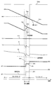
- FIG. 3 is a time chart showing an image of a control result by the ECU according to the present embodiment.
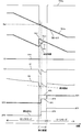
- FIG. 4 is a time chart showing an image according to a comparative example.
- the first chart shows the time change of the torque.
- “TQ1r” is the requested first torque
- “TQ2c” is the switching target second torque
- “TQe” is the estimated torque.
- the requested first torque is the final target first torque
- the switching target second torque is the final target second torque.
- the actual torque is represented by a dotted line in the chart.
- actual torque is not measured by actual engine control.
- the actual torque line drawn on the chart is an image line supported by the test results.
- the second chart in FIGS. 3 and 4 shows the time variation of the air amount.
- “KLt” is the target air amount
- “KLe” is the estimated air amount
- “KLi” is the intermediate air amount.
- the actual air amount is represented by a dotted line together with these air amounts.
- the actual air amount is not measured by actual engine control.
- the actual air volume line drawn on the chart is an image line supported by the test results.
- 3 and 4 show the change over time in the target efficiency for switching.
- ⁇ tc is the target efficiency for switching.
- the target efficiency for switching is the final target efficiency.
- 3 and 4 show the change over time in the indicated ignition timing efficiency.
- ⁇ i is the indicated ignition timing efficiency.
- SA is the ignition timing.
- retard limit of the ignition timing is represented by a two-dot chain line.
- time change of the ignition timing when not guarded at the retard limit is represented by a dotted line.
- the charts in the sixth row in FIGS. 3 and 4 show the time variation of the air-fuel ratio.
- “AFt” is the target air-fuel ratio
- “AFh” is the virtual air-fuel ratio
- “AF1” is the first air-fuel ratio
- “AF2” is the second air-fuel ratio
- “AF3” is the third air-fuel ratio.
- the time chart of the actual air-fuel ratio is shown in the seventh chart in FIGS.
- the virtual air-fuel ratio is switched from the first air-fuel ratio to the second air-fuel ratio prior to switching the target air-fuel ratio from the first air-fuel ratio to the second air-fuel ratio.
- the target air amount increases stepwise up to the air amount corresponding to the second air-fuel ratio, and the actual air amount also greatly increases so as to follow the target air amount.
- the target air amount prior to switching of the target air-fuel ratio it becomes possible to increase the air amount to an amount corresponding to the second air-fuel ratio by the time of switching of the target air-fuel ratio.
- the amount of air becomes more than the amount of air necessary to achieve the required first torque by the amount that the target air amount is increased prior to the switching of the target air-fuel ratio.
- the torque increase due to the excess air amount is offset by the torque decrease due to the retard of the ignition timing.
- the ignition timing is limited by the retard limit because of the guard function to prevent misfire, the ignition timing cannot be retarded by the necessary amount, and the increase in torque due to excessive air volume cannot be avoided. End up.
- the actual torque temporarily becomes excessive with respect to the requested first torque, and the smooth decrease in torque commensurate with the driver's deceleration request is impaired.
- both the target air-fuel ratio and the virtual air-fuel ratio are maintained at the first air-fuel ratio, which is the theoretical air-fuel ratio, until the required first torque decreases to the level of the reference value represented by “Ref”. Therefore, the target air amount calculated from the requested first torque and the virtual air-fuel ratio decreases in conjunction with the decrease in the requested first torque.
- the target second torque for switching is set to an invalid value in response to the target air-fuel ratio and the virtual air-fuel ratio matching. If the target second torque for switching is an invalid value, the indicated ignition timing efficiency is 1, so the ignition timing is maintained at the optimal ignition timing.
- the ignition timing changes according to the decrease in the required first torque. This is a change corresponding to the fact that the optimal ignition timing changes according to the engine speed and the air amount.
- the target air-fuel ratio is maintained at the stoichiometric air-fuel ratio, while the virtual air-fuel ratio is made lean in a stepwise manner.
- the operation with the second air-fuel ratio that is a lean air-fuel ratio requires a larger amount of air than the amount of air required for the operation with the first air-fuel ratio that is the stoichiometric air-fuel ratio. For this reason, when the virtual air-fuel ratio used for calculation of the target air amount is switched to the second air-fuel ratio in a stepwise manner, the target air amount also increases in a stepwise manner at the time of the switching.
- the actual air amount and the estimated air amount that is the estimated value do not increase stepwise, but increase after the target air amount. I will do it.
- the target air-fuel ratio is switched from the first air-fuel ratio to the third air-fuel ratio.
- the actual air amount and the estimated air amount further increase and converge to the target air amount, and eventually, the difference between the target air amount and the estimated air amount becomes less than the threshold value.
- the target air-fuel ratio is switched from the third air-fuel ratio to the second air-fuel ratio.
- the requested second torque for switching is an effective value from when the requested first torque falls below the reference value until the target air-fuel ratio and the virtual air-fuel ratio coincide again after the target air-fuel ratio deviates from the virtual air-fuel ratio.
- the value is the same as the first torque.
- the estimated torque calculated based on the estimated air amount and the target air-fuel ratio is obtained from the first air-fuel ratio of the virtual air-fuel ratio to the second air-fuel ratio while the target air-fuel ratio is maintained at the first air-fuel ratio. As the estimated amount of air increases due to switching, it gradually increases compared to the required first torque.
- the estimated torque decreases stepwise.
- the target air-fuel ratio is switched from the first air-fuel ratio to the third air-fuel ratio at the timing when the estimated air amount reaches the air amount at which the required first torque can be achieved under the third air-fuel ratio.
- the estimated torque immediately after switching of the fuel ratio matches the required first torque.
- the estimated torque gradually increases again compared to the requested first torque.
- the estimated air amount converges to the target air amount, and the target air-fuel ratio is switched from the third air-fuel ratio to the second air-fuel ratio, whereby the estimated torque decreases stepwise and matches the requested first torque.
- the command ignition timing efficiency which is the ratio of the switching target second torque, is a value smaller than one. Specifically, the indicated ignition timing efficiency monotonously decreases after the virtual air-fuel ratio is switched from the first air-fuel ratio to the second air-fuel ratio until the target air-fuel ratio is switched from the first air-fuel ratio to the third air-fuel ratio. I will do it. Then, it is returned to 1 when the target air-fuel ratio is switched from the first air-fuel ratio to the third air-fuel ratio. Thereafter, the command ignition timing efficiency decreases monotonously again until the target air-fuel ratio is switched from the third air-fuel ratio to the second air-fuel ratio.
- ⁇ Indicated ignition timing efficiency determines the ignition timing. The smaller the value of the commanded ignition timing efficiency, the larger the retard amount of the ignition timing with respect to the optimum ignition timing.
- the ignition timing responds to a decrease in the indicated ignition timing efficiency until the target air-fuel ratio is switched from the first air-fuel ratio to the third air-fuel ratio after the virtual air-fuel ratio is switched from the first air-fuel ratio to the second air-fuel ratio. Then it is delayed monotonously.
- the instruction ignition timing efficiency being returned to 1 when the target air-fuel ratio is switched from the first air-fuel ratio to the third air-fuel ratio
- the ignition timing is returned to the optimum ignition timing again.
- the ignition timing is retarded monotonically again in response to a decrease in the commanded ignition timing efficiency.
- the ignition timing is not continuously retarded monotonically during the transition period, but is temporarily returned to the optimal ignition timing in the middle, and the optimal ignition timing is set again. The starting point is monotonously retarded.
- the operation mode can be switched from the operation using the first air-fuel ratio to the operation using the second air-fuel ratio without causing torque fluctuation.
- the logic of the arithmetic unit 408 is different between the second embodiment and the first embodiment.
- the entire logic of the arithmetic unit 122 in which the arithmetic unit 408 is accommodated is the same as that of the first embodiment, and the logic of the arithmetic unit 122 according to this embodiment can also be represented in FIG.
- the overall logic of the ECU is the same as that of the first embodiment, and the logic of the ECU according to the present embodiment can also be represented in FIG.
- FIG. 5 is a time chart showing the logic of the arithmetic unit 408 according to the present embodiment.
- the first chart in FIG. 5 shows the change over time of the requested first torque.
- the second chart shows the time variation of the target air amount, the estimated air amount, the intermediate air amount, and the minimum air amount.
- the minimum air amount is the minimum value of the air amount that does not cause misfire under the third air-fuel ratio. In the figure, the minimum air amount is indicated as “KLmf”.
- the third chart shows changes over time in the virtual air-fuel ratio and the target air-fuel ratio.
- the arithmetic unit 408 calculates the minimum air amount based on various conditions related to misfire such as engine speed and intake air temperature.
- the arithmetic unit 408 detects that the virtual air-fuel ratio has been switched from the first air-fuel ratio to the second air-fuel ratio, it performs a comparison between the intermediate air amount and the estimated air amount for each control step, Comparison with the estimated air amount is also performed for each control step. Then, when the estimated air amount is equal to or greater than the intermediate air amount and the estimated air amount is equal to or greater than the minimum air amount, the arithmetic unit 408 switches the target air-fuel ratio from the first air-fuel ratio to the third air-fuel ratio.
- the calculation of the minimum air amount by the arithmetic unit 408 is performed for each control step until the target air-fuel ratio is switched from the first air-fuel ratio to the third air-fuel ratio after the virtual air-fuel ratio is switched from the first air-fuel ratio to the second air-fuel ratio.
- the processing after switching the target air-fuel ratio to the third air-fuel ratio is the same as the processing in the first embodiment.
- the arithmetic unit 408 switches the target air-fuel ratio from the third air-fuel ratio to the second air-fuel ratio.
- the operation mode switching logic employed in the present embodiment it is possible to prevent misfire due to a shortage of the air amount when the target air-fuel ratio is switched to the third air-fuel ratio.
- the minimum air amount is smaller than the intermediate air amount, a control result similar to the control result according to the first embodiment is obtained.
- the third embodiment and the first and second embodiments are different in the logic of the arithmetic unit 408.
- the entire logic of the arithmetic unit 122 in which the arithmetic unit 408 is accommodated is the same as that of the first embodiment, and the logic of the arithmetic unit 122 according to this embodiment can also be represented in FIG.
- the overall logic of the ECU is the same as that of the first embodiment, and the logic of the ECU according to the present embodiment can also be represented in FIG.
- the target air-fuel ratio is switched to the third air-fuel ratio before the ignition timing reaches the retard limit, and the ignition timing is advanced to the optimal ignition timing.
- the ignition timing will reach the retard limit before the target air-fuel ratio is switched to the third air-fuel ratio due to special operating conditions and individual differences between engines.
- a function for dealing with such a case is added to the arithmetic unit 408 according to the present embodiment.
- the arithmetic unit 408 sets the air / fuel ratio to the third air / fuel ratio and sets the ignition timing to the optimal ignition timing when the ignition timing is retarded to the retard limit within the transition period of the operation mode.
- a torque that can be achieved by the current estimated air amount (hereinafter referred to as torque A) is calculated.
- torque B a torque that can be achieved by the current estimated air amount when the air-fuel ratio is maintained at the first air-fuel ratio and the ignition timing is maintained at the retard limit
- torque B a shortage of torque A with respect to the requested first torque and an excess of torque B with respect to the requested first torque are respectively calculated, and it is determined which of the shortage and excess is smaller.
- the arithmetic unit 408 immediately switches the target air-fuel ratio from the first air-fuel ratio to the third air-fuel ratio. On the other hand, if the excess amount is smaller, the arithmetic unit 408 maintains the target air-fuel ratio at the first air-fuel ratio, waits for the estimated air amount to reach the intermediate air amount, and changes the target air-fuel ratio from the first air-fuel ratio to the first air-fuel ratio. Switch to 3 air-fuel ratio.
- the processing after switching the target air-fuel ratio to the third air-fuel ratio is the same as the processing in the first embodiment. When the difference between the target air amount and the estimated air amount becomes equal to or less than a predetermined threshold, the arithmetic unit 408 switches the target air-fuel ratio from the third air-fuel ratio to the second air-fuel ratio.
- 6 and 7 are time charts showing an image of a control result by the ECU according to the present embodiment. 6 and 7 show the control results when the ignition timing reaches the retard limit before the target air-fuel ratio is switched to the third air-fuel ratio.
- Each time chart is composed of a plurality of charts, and the contents shown in each chart are the same as those in the time chart of FIG.
- the control result shown in FIG. 6 is a control result in a case where it is determined that the shortage of torque A with respect to the requested first torque is smaller than the excess amount of torque B with respect to the requested first torque.
- the target air-fuel ratio is switched from the first air-fuel ratio to the third air-fuel ratio immediately after the ignition timing is retarded to the retard limit. Since the estimated air amount has not reached the intermediate air amount at this time, the estimated torque becomes smaller than the requested first torque by switching the target air-fuel ratio to the third air-fuel ratio, and the indicated ignition timing efficiency is returned to 1. .
- the ignition timing is advanced stepwise from the retard limit to the optimal ignition timing.
- the actual torque and the estimated torque temporarily decrease with respect to the requested first torque when the target air-fuel ratio is switched to the third air-fuel ratio.
- the estimated torque exceeds the required first torque.
- an increase in the actual torque with respect to the required first torque is avoided by the effective delay of the ignition timing.
- the control result shown in FIG. 7 is a control result in a case where it is determined that the excessive amount of torque B with respect to the requested first torque is smaller than the insufficient amount of torque A with respect to the requested first torque.
- the target air-fuel ratio is maintained at the first air-fuel ratio, and the ignition timing remains stuck to the retard limit.
- the actual torque temporarily becomes excessive with respect to the requested first torque.
- the target air-fuel ratio is switched from the first air-fuel ratio to the third air-fuel ratio, and accordingly the ignition timing is advanced stepwise to the optimal ignition timing.
- the actual torque again matches the requested first torque.
- an increase in the actual torque with respect to the requested first torque is avoided by the effective delay of the ignition timing.
- the engine to be controlled in this embodiment is a spark ignition type four-cycle reciprocating engine and a supercharged lean burn engine equipped with a turbocharger.
- the actuator operated by the ECU that controls the operation of the engine includes a wastegate valve (hereinafter referred to as WGV) provided in the turbocharger.
- WGV is a supercharging characteristic variable actuator that changes the supercharging characteristic of the turbocharger. Since the supercharging characteristic of the turbocharger changes the amount of air, WGV is included in the first actuator that changes the amount of air, like the throttle and VVT.
- FIG. 5 is a block diagram showing the logic of the ECU according to the present embodiment.
- the ECU includes an engine controller 100 and a powertrain manager 200.
- various functions included in the powertrain manager 200 are represented by blocks.
- the block which shows the function which is common with the thing of ECU which concerns on Embodiment 1 is attached
- the block indicating the engine controller 100 among various functions provided in the engine controller 100, functions related to the cooperative operation of the actuator are represented by blocks.
- it demonstrates centering on the block which shows the difference from Embodiment 1, ie, the function peculiar to control of a supercharged lean burn engine.
- the powertrain manager 200 includes an arithmetic unit 210 in addition to the arithmetic units 202, 204, 206, and 208 common to the first embodiment.
- the arithmetic unit 210 calculates the requested third torque and transmits it to the engine controller 100.
- the required third torque is described as “TQ3r”.
- the third torque is a torque required for the engine constantly or over a long period of time.
- the relationship between the third torque and the first torque is similar to the relationship between the first torque and the second torque. In other words, when viewed from the side of the first torque, the first torque is realized with a kind of torque that has higher urgency or priority than the third torque and requires high responsiveness of the engine, that is, earlier.
- the requested third torque is a requested value of the third torque that the powertrain manager 200 requests from the engine. If the three types of required torques calculated by the powertrain manager 200 are arranged in the order of urgency or priority, that is, in order of the responsiveness required for the engine, the required second torque, the required first torque, and the required third Torque order.
- the arithmetic unit 210 calculates the requested third torque based on a signal that responds to the opening of the accelerator pedal.
- the required third torque corresponds to the required torque in the present invention together with the required first torque.
- a request torque that is obtained by removing a pulse component in a temporary torque-down direction from the request first torque may be used as the request third torque.
- the engine controller 100 includes three large arithmetic units 120, 140, and 160, as in the first embodiment.
- the large arithmetic unit 120 includes an arithmetic unit 130 in addition to the arithmetic units 122, 124, 126, and 128 common to the first embodiment.
- the arithmetic unit 130 is classified as a third torque among the torques required to maintain the current engine operating state or to realize a predetermined operating state as a control parameter for the engine. Calculate the torque.
- the torque calculated by the arithmetic unit 130 is referred to as other third torque.
- the other third torque is indicated as “TQ3etc”.
- the arithmetic unit 130 outputs a valid value only when such torque is actually needed, and calculates an invalid value while such torque is not needed.
- the invalid value is set to a value larger than the maximum indicated torque that the engine can output.
- the large arithmetic unit 140 includes an arithmetic unit 148 in addition to the arithmetic units 142, 144, and 146 common to the first embodiment.
- the arithmetic unit 148 is configured to adjust the third torque.
- the requested third torque and the other third torque are input to the arithmetic unit 148.
- the arithmetic unit 148 arbitrates them and outputs the arbitrated torque as the finally determined target third torque.
- the finally determined target third torque is described as “TQ3t”.
- As an arbitration method in the arithmetic unit 148 minimum value selection is used. Therefore, when a valid value is not output from the arithmetic unit 130, the requested third torque given from the powertrain manager 200 is calculated as the target third torque.
- the large arithmetic unit 160 treats all of the target first torque, target second torque, and target third torque input from the large arithmetic unit 140 as target values of torque for the engine. Therefore, the large arithmetic unit 160 according to the present embodiment includes an arithmetic unit 182 instead of the arithmetic unit 162 according to the first embodiment, and includes an arithmetic unit 184 instead of the arithmetic unit 164 according to the first embodiment. .
- the calculation unit 182 receives the target first torque and the target third torque, and further inputs the target efficiency and the virtual air-fuel ratio.
- the arithmetic unit 182 corresponds to the target air amount calculation means in the present invention.
- the arithmetic unit 182 uses the same method as the arithmetic unit 162 according to the first embodiment to use the target efficiency and the virtual air-fuel ratio to achieve the target air amount (hereinafter referred to as target first air) for achieving the target first torque. Quantity) from the target first torque.
- the target first air amount is described as “KL1t”.
- the target first air amount is used for calculation of the target valve timing by the arithmetic unit 178.
- the calculation unit 182 uses the target efficiency and the virtual air-fuel ratio to achieve the target air amount (hereinafter, the target third air amount) for achieving the target third torque. ) Is calculated backward from the target third torque.
- the target third air amount is described as “KL3t”.
- the target efficiency and the virtual air-fuel ratio are used as parameters that give the conversion efficiency of the air amount into torque. If the value of the virtual air-fuel ratio is changed as in Embodiment 1 in the calculation of the target first air amount, the value of the virtual air-fuel ratio is similarly changed in the calculation of the target third air amount.
- the arithmetic unit 184 performs a reverse calculation of the target intake pipe pressure from the target first air amount by a method common to the arithmetic unit 164 according to the first embodiment.
- the target intake pipe pressure is indicated as “Pmt”.
- the target intake pipe pressure is used for calculation of the target throttle opening by the arithmetic unit 166.
- the arithmetic unit 184 calculates the target boost pressure from the target third air amount.
- the target boost pressure is indicated as “Pct”.
- the target third air amount is converted into the intake pipe pressure by the same method as that for calculating the target intake pipe pressure.
- the reserve pressure is added to the intake pipe pressure obtained by converting the target third air amount, and the total value is calculated as the target supercharging pressure.
- the reserve pressure is a minimum margin of the supercharging pressure with respect to the intake pipe pressure.
- the reserve pressure may be a fixed value, but may be changed in conjunction with the intake pipe pressure, for example.
- the large arithmetic unit 160 further includes an arithmetic unit 186.
- the arithmetic unit 186 calculates a target wastegate valve opening that is a target value of the wastegate valve opening based on the target boost pressure.
- the target wastegate valve opening is indicated as “WGV”.
- WGV the target wastegate valve opening
- a map or model that associates the boost pressure with the wastegate valve opening is used.
- the target wastegate valve opening calculated by the arithmetic unit 186 is converted into a signal for driving the WGV 10 and transmitted to the WGV 10 via the interface 115 of the ECU.
- the arithmetic unit 186 also corresponds to the first actuator control means in the present invention. Note that the operation amount of the WGV 10 may be the duty ratio of the solenoid that drives the WGV 10 instead of the waste gate valve opening.
- the air-fuel ratio can be adjusted while smoothly changing the torque according to the driver's request.
- the problem of switching with good response can also be achieved in a supercharged lean burn engine.
- the engine operating range is specified by the intake pipe pressure and the engine speed.
- the lean mode area where the lean mode is selected is set to the low / medium rotation / low / medium load area, and a part of the high load side overlaps with the supercharging area where the intake pipe pressure is higher than the atmospheric pressure. .
- the setting of the operation region is stored as a map. The ECU executes the operation mode switching according to the map.
- the timing of switching the target air-fuel ratio in the first embodiment may be a timing after the time when the estimated air amount reaches the intermediate air amount. Since there is an error between the actual air amount and the estimated air amount, the actual air amount may not reach the intermediate air amount when the target air-fuel ratio is switched from the first air-fuel ratio to the third air-fuel ratio. . In this case, the actual torque is insufficient with respect to the required torque. Therefore, it is preferable to wait for the actual air amount to reach the intermediate air amount and switch the target air-fuel ratio to the third air-fuel ratio in order to avoid a shortage of torque. However, it should be noted that there is a high possibility that the ignition timing will reach the retard limit if the timing for switching the target air-fuel ratio is delayed too much.
- the air-fuel ratio (virtual air-fuel ratio) used for calculating the target air amount can be replaced with the equivalence ratio.
- the equivalence ratio is also a parameter that gives the conversion efficiency of the air amount into torque and corresponds to a parameter corresponding to the air-fuel ratio.
- the excess air ratio can be used as a parameter that gives the conversion efficiency of the air amount into torque.
- variable lift mechanism that makes the lift amount of the intake valve variable can also be used.
- the variable lift mechanism can be used alone instead of the throttle, or can be used in combination with another first actuator such as a throttle or VVT. VVT may be omitted.
- a variable nozzle can also be used as the supercharging characteristic variable actuator that changes the supercharging characteristic of the turbocharger. Further, if the turbocharger is assisted by an electric motor, the electric motor can be used as a supercharging characteristic variable actuator.
- the injector as the second actuator is not limited to the port injector.
- An in-cylinder injector that directly injects fuel into the combustion chamber may be used, or both a port injector and an in-cylinder injector may be used in combination.
- the first air / fuel ratio is not limited to the stoichiometric air / fuel ratio. It is also possible to set the air-fuel ratio leaner than the stoichiometric air-fuel ratio to the first air-fuel ratio and set the air-fuel ratio leaner than the first air-fuel ratio to the second air-fuel ratio.
- variable valve timing mechanism 10 waste gate valve 100 engine controller 105 interface 200 as required torque receiving means power train manager 162; 182 arithmetic units 164, 166; 178 as target air amount calculating means Arithmetic units 174, 176 as actuator control means Arithmetic units 168, 170, 172 as second actuator control means Arithmetic unit 404 as third actuator control means Arithmetic units 406, 408 as parameter value changing means Target air-fuel ratio switching means Arithmetic unit as
Landscapes
- Engineering & Computer Science (AREA)
- General Engineering & Computer Science (AREA)
- Chemical & Material Sciences (AREA)
- Combustion & Propulsion (AREA)
- Mechanical Engineering (AREA)
- Signal Processing (AREA)
- Theoretical Computer Science (AREA)
- Computer Hardware Design (AREA)
- Microelectronics & Electronic Packaging (AREA)
- Combined Controls Of Internal Combustion Engines (AREA)
- Electrical Control Of Air Or Fuel Supplied To Internal-Combustion Engine (AREA)
- Control Of Throttle Valves Provided In The Intake System Or In The Exhaust System (AREA)
- Output Control And Ontrol Of Special Type Engine (AREA)
- Electrical Control Of Ignition Timing (AREA)
Abstract
Description
以下、本発明の実施の形態1について図を参照して説明する。
次に、本発明の実施の形態2について図を参照して説明する。
次に、本発明の実施の形態3について図を参照して説明する。
次に、本発明の実施の形態4について図を参照して説明する。
本発明は上述の実施の形態に限定されるものではなく、本発明の趣旨を逸脱しない範囲で種々変形して実施することができる。例えば、以下のような変形例を採用してもよい。
4 インジェクタ
6 点火装置
8 可変バルブタイミング機構
10 ウエストゲートバルブ
100 エンジンコントローラ
105 要求トルク受信手段としてのインタフェース
200 パワートレインマネージャ
162;182 目標空気量算出手段としての演算ユニット
164、166;178 第1アクチュエータ制御手段としての演算ユニット
174、176 第2アクチュエータ制御手段としての演算ユニット
168、170、172 第3アクチュエータ制御手段としての演算ユニット
404 パラメータ値変更手段としての演算ユニット
406、408 目標空燃比切替手段としての演算ユニット
Claims (9)
- 筒内に吸入される空気の量を変化させる第1アクチュエータと、筒内に燃料を供給する第2アクチュエータと、筒内の混合気に点火する第3アクチュエータとを有し、第1空燃比による運転と前記第1空燃比よりもリーンな第2空燃比による運転とを選択可能に構成された内燃機関の制御装置において、
要求トルクを受信する要求トルク受信手段と、
空気量のトルクへの変換効率を与えるパラメータを用いて前記要求トルクを達成するための目標空気量を前記要求トルクから逆算する目標空気量算出手段と、
前記第1空燃比による運転から前記第2空燃比による運転へ運転モードを切り替える条件が満たされたことに応答して、前記パラメータに含まれる仮想空燃比を前記第1空燃比から前記第2空燃比に変更する仮想空燃比変更手段と、
前記仮想空燃比が前記第1空燃比から前記第2空燃比へ変更された後、目標空燃比を前記第1空燃比から前記第1空燃比と前記第2空燃比との中間の第3空燃比に切り替え、さらに前記第3空燃比から前記第2空燃比へ切り替える目標空燃比切替手段と、
前記目標空気量に基づいて前記第1アクチュエータの操作量を決定し、前記操作量に従って前記第1アクチュエータを操作する第1アクチュエータ制御手段と、
前記目標空燃比に基づいて燃料供給量を決定し、前記燃料供給量に従って前記第2アクチュエータを操作する第2アクチュエータ制御手段と、
前記第1アクチュエータの操作量と前記目標空燃比とから推定されるトルクと前記要求トルクとに基づいて前記要求トルクを達成するための点火時期を決定し、前記点火時期に従って前記第3アクチュエータを操作する第3アクチュエータ制御手段と、
を備えることを特徴とする内燃機関の制御装置。 - 前記目標空燃比切替手段は、前記第1アクチュエータの操作量から推定される空気量が前記第3空燃比のもとで前記要求トルクを達成できる空気量に到達したことに応答して、前記目標空燃比を前記第1空燃比から前記第3空燃比に切り替えることを特徴とする請求項1に記載の内燃機関の制御装置。
- 前記目標空燃比切替手段は、前記第3空燃比のもとで前記要求トルクを達成できる空気量が失火を生じさせない最小空気量よりも少ない場合、前記第1アクチュエータの操作量から推定される空気量が前記最小空気量を超えたことに応答して、前記目標空燃比を前記第1空燃比から前記第3空燃比に切り替えることを特徴とする請求項2に記載の内燃機関の制御装置。
- 前記目標空燃比切替手段は、前記第1アクチュエータの操作量から推定される空気量が前記第3空燃比のもとで要求トルクを達成できる空気量に到達する前に点火時期が遅角限界まで遅角された場合、前記第3空燃比のもとで達成できるトルクの前記要求トルクに対する不足分が前記第1空燃比のもとで達成できるトルクの前記要求トルクに対する過剰分よりも小さいことを条件として、前記目標空燃比を前記第1空燃比から前記第3空燃比に切り替えることを特徴とする請求項2又は3に記載の内燃機関の制御装置。
- 前記目標空燃比切替手段は、前記目標空燃比の前記第3空燃比への切り替え後、前記目標空気量と前記第1アクチュエータの操作量から推定される空気量との差が閾値以下になってから、前記目標空燃比を前記第3空燃比から前記第2空燃比へ切り替えることを特徴とする請求項1乃至4の何れか1項に記載の内燃機関の制御装置。
- 前記目標空燃比切替手段は、前記目標空燃比の前記第3空燃比への切り替え後、一定時間が経過してから、前記目標空燃比を前記第3空燃比から前記第2空燃比へ切り替えることを特徴とする請求項1乃至4の何れか1項に記載の内燃機関の制御装置。
- 前記第1アクチュエータはスロットルを含み、
前記第1アクチュエータ制御手段は、前記目標空気量から算出される目標吸気管圧に基づいて目標スロットル開度を決定し、前記目標スロットル開度に従って前記スロットルを操作することを特徴とする請求項1乃至6の何れか1項に記載の内燃機関の制御装置。 - 前記第1アクチュエータは吸気バルブのバルブタイミングを変化させる可変バルブタイミング機構を含み、
前記第1アクチュエータ制御手段は、前記目標空気量に基づいて目標バルブタイミングを決定し、前記目標バルブタイミングに従って前記可変バルブタイミング機構を操作することを特徴とする請求項1乃至7の何れか1項に記載の内燃機関の制御装置。 - 前記内燃機関は過給器を備えた過給エンジンであり、
前記第1アクチュエータは前記過給器の過給特性を変化させる過給特性可変アクチュエータを含み、
前記第1アクチュエータ制御手段は、前記目標空気量から算出される目標過給圧に基づいて前記過給特性可変アクチュエータの操作量を決定し、前記操作量に従って前記過給特性可変アクチュエータを操作することを特徴とする請求項1乃至8の何れか1項に記載の内燃機関の制御装置。
Priority Applications (5)
| Application Number | Priority Date | Filing Date | Title |
|---|---|---|---|
| EP13885388.2A EP3006704B1 (en) | 2013-05-24 | 2013-05-24 | Control device for internal combustion engine |
| CN201380076805.8A CN105247194B (zh) | 2013-05-24 | 2013-05-24 | 内燃机的控制装置 |
| JP2015518029A JP6041051B2 (ja) | 2013-05-24 | 2013-05-24 | 内燃機関の制御装置 |
| PCT/JP2013/064514 WO2014188595A1 (ja) | 2013-05-24 | 2013-05-24 | 内燃機関の制御装置 |
| US14/892,696 US10221799B2 (en) | 2013-05-24 | 2013-05-24 | Control device for internal combustion engine |
Applications Claiming Priority (1)
| Application Number | Priority Date | Filing Date | Title |
|---|---|---|---|
| PCT/JP2013/064514 WO2014188595A1 (ja) | 2013-05-24 | 2013-05-24 | 内燃機関の制御装置 |
Publications (1)
| Publication Number | Publication Date |
|---|---|
| WO2014188595A1 true WO2014188595A1 (ja) | 2014-11-27 |
Family
ID=51933176
Family Applications (1)
| Application Number | Title | Priority Date | Filing Date |
|---|---|---|---|
| PCT/JP2013/064514 Ceased WO2014188595A1 (ja) | 2013-05-24 | 2013-05-24 | 内燃機関の制御装置 |
Country Status (5)
| Country | Link |
|---|---|
| US (1) | US10221799B2 (ja) |
| EP (1) | EP3006704B1 (ja) |
| JP (1) | JP6041051B2 (ja) |
| CN (1) | CN105247194B (ja) |
| WO (1) | WO2014188595A1 (ja) |
Cited By (1)
| Publication number | Priority date | Publication date | Assignee | Title |
|---|---|---|---|---|
| JP2018017154A (ja) * | 2016-07-27 | 2018-02-01 | 本田技研工業株式会社 | 車両の制御装置 |
Families Citing this family (11)
| Publication number | Priority date | Publication date | Assignee | Title |
|---|---|---|---|---|
| US20160123250A1 (en) * | 2013-05-24 | 2016-05-05 | Toyota Jidosha Kabushiki Kaisha | Device for controlling internal combustion engine |
| DE112013007133B9 (de) * | 2013-06-03 | 2019-07-18 | Toyota Jidosha Kabushiki Kaisha | Steuervorrichtung für Verbrennungsmotor mit Turbolader |
| JP6041052B2 (ja) * | 2013-06-06 | 2016-12-07 | トヨタ自動車株式会社 | 過給器付き内燃機関の制御装置 |
| CN105283648B (zh) * | 2013-06-11 | 2017-12-26 | 丰田自动车株式会社 | 内燃机的控制装置 |
| KR20170128785A (ko) * | 2016-05-13 | 2017-11-24 | 현대자동차주식회사 | 차량의 egr밸브 제어방법 및 그 제어시스템 |
| US10626840B2 (en) * | 2017-06-29 | 2020-04-21 | Ford Global Technologies, Llc | Methods and systems for spark timing control |
| JP7106993B2 (ja) * | 2018-05-31 | 2022-07-27 | 株式会社デンソー | 内燃機関の制御装置および内燃機関の制御方法 |
| JP7124518B2 (ja) * | 2018-07-26 | 2022-08-24 | マツダ株式会社 | 圧縮着火式エンジンの制御装置 |
| JP7131170B2 (ja) * | 2018-07-26 | 2022-09-06 | マツダ株式会社 | 圧縮着火式エンジンの制御装置 |
| JP7131169B2 (ja) * | 2018-07-26 | 2022-09-06 | マツダ株式会社 | 圧縮着火式エンジンの制御装置 |
| CN121452081A (zh) * | 2024-08-01 | 2026-02-03 | 康明斯有限公司 | 防止火花点火式内燃发动机中瞬态期间爆震和提前点火的燃烧控制 |
Citations (7)
| Publication number | Priority date | Publication date | Assignee | Title |
|---|---|---|---|---|
| JPH1068375A (ja) * | 1996-08-28 | 1998-03-10 | Mitsubishi Motors Corp | 筒内噴射式内燃機関の点火時期制御装置 |
| JPH10299536A (ja) * | 1997-04-28 | 1998-11-10 | Mitsubishi Motors Corp | 筒内噴射型火花点火式内燃エンジンの制御装置 |
| JPH1122609A (ja) | 1997-07-08 | 1999-01-26 | Nissan Motor Co Ltd | 内燃機関の制御装置 |
| JPH11159377A (ja) * | 1997-12-01 | 1999-06-15 | Hitachi Ltd | エンジン制御装置 |
| JP2001227377A (ja) * | 2000-02-18 | 2001-08-24 | Denso Corp | 筒内噴射式内燃機関の制御装置 |
| JP2005069029A (ja) * | 2003-08-27 | 2005-03-17 | Toyota Motor Corp | 内燃機関の制御装置 |
| JP2007126989A (ja) * | 2005-11-01 | 2007-05-24 | Honda Motor Co Ltd | 内燃機関の空燃比制御装置 |
Family Cites Families (32)
| Publication number | Priority date | Publication date | Assignee | Title |
|---|---|---|---|---|
| JPS6183467A (ja) * | 1984-09-29 | 1986-04-28 | Mazda Motor Corp | エンジンの制御装置 |
| US5272871A (en) * | 1991-05-24 | 1993-12-28 | Kabushiki Kaisha Toyota Chuo Kenkyusho | Method and apparatus for reducing nitrogen oxides from internal combustion engine |
| JPH06323165A (ja) * | 1993-05-17 | 1994-11-22 | Hitachi Ltd | ガスタービン用制御装置及び制御方法 |
| JP3862288B2 (ja) | 1993-10-20 | 2006-12-27 | 株式会社日立製作所 | 内燃機関の空燃比制御装置 |
| JPH0960543A (ja) | 1995-08-24 | 1997-03-04 | Hitachi Ltd | エンジン制御装置 |
| US5850815A (en) * | 1996-04-17 | 1998-12-22 | Honda Giken Kogyo Kabushiki Kaisha | Control system and control process in internal combustion engine |
| JP4036906B2 (ja) * | 1996-05-15 | 2008-01-23 | 三菱電機株式会社 | 筒内噴射内燃機関の制御装置 |
| JP3680491B2 (ja) * | 1997-06-02 | 2005-08-10 | 日産自動車株式会社 | 内燃機関の制御装置 |
| JP3500936B2 (ja) * | 1997-11-25 | 2004-02-23 | 株式会社日立製作所 | 筒内噴射エンジンの制御装置 |
| JP3815006B2 (ja) * | 1997-12-09 | 2006-08-30 | 日産自動車株式会社 | 内燃機関の制御装置 |
| DE19813381A1 (de) * | 1998-03-26 | 1999-10-07 | Bosch Gmbh Robert | Verfahren zum Betreiben einer Brennkraftmaschine insbesondere eines Kraftfahrzeugs |
| JP3484342B2 (ja) * | 1998-04-15 | 2004-01-06 | トヨタ自動車株式会社 | バキュームブースタ装置およびブレーキ装置 |
| US6497212B2 (en) * | 2000-02-10 | 2002-12-24 | Denso Corporation | Control apparatus for a cylinder injection type internal combustion engine capable of suppressing undesirable torque shock |
| US6519933B2 (en) * | 2000-03-21 | 2003-02-18 | Toyota Jidosha Kabushiki Kaisha | Internal combustion engine having variable valve control system and NOx catalyst |
| JP4590773B2 (ja) * | 2000-06-22 | 2010-12-01 | 株式会社デンソー | 車両統合制御システム |
| US6604504B2 (en) * | 2001-06-19 | 2003-08-12 | Ford Global Technologies, Llc | Method and system for transitioning between lean and stoichiometric operation of a lean-burn engine |
| DE10148871C1 (de) * | 2001-10-04 | 2003-06-12 | Bosch Gmbh Robert | Verfahren zum Betreiben einer Brennkraftmaschine, Steuergerät für eine Brennkraftmaschine und Brennkraftmaschine |
| JP3816416B2 (ja) * | 2002-03-28 | 2006-08-30 | 三菱電機株式会社 | 電子スロットル制御システムのフェイルセーフ装置 |
| JP3736498B2 (ja) * | 2002-04-26 | 2006-01-18 | トヨタ自動車株式会社 | 筒内噴射式内燃機関の蒸発燃料処理装置 |
| US6754578B1 (en) * | 2003-03-27 | 2004-06-22 | Ford Global Technologies, Llc | Computer instructions for control of multi-path exhaust system in an engine |
| JP4016905B2 (ja) * | 2003-08-08 | 2007-12-05 | トヨタ自動車株式会社 | 内燃機関の制御装置 |
| JP4251081B2 (ja) * | 2003-11-21 | 2009-04-08 | 株式会社デンソー | 内燃機関の制御装置 |
| DE102004033073A1 (de) * | 2004-07-08 | 2006-01-26 | Robert Bosch Gmbh | Verfahren zum Betrieb einer Brennkraftmaschine |
| JP4548486B2 (ja) * | 2008-01-09 | 2010-09-22 | トヨタ自動車株式会社 | 内燃機関の制御装置 |
| EP2267284A4 (en) * | 2008-04-25 | 2012-01-11 | Toyota Motor Co Ltd | CHARGER CONTROL FOR INTERNAL COMBUSTION ENGINE |
| EP2314845B1 (en) * | 2008-06-30 | 2014-08-13 | Nissan Motor Co., Ltd. | Controller of internal combustion engine with variable dynamic valve gear mechanism |
| JP4832542B2 (ja) * | 2009-03-18 | 2011-12-07 | 本田技研工業株式会社 | 内燃機関の制御装置 |
| JP5273480B2 (ja) * | 2009-11-04 | 2013-08-28 | トヨタ自動車株式会社 | 内燃機関の吸入空気量制御装置 |
| EP2565433B1 (en) * | 2010-04-27 | 2014-09-24 | Toyota Jidosha Kabushiki Kaisha | Control device for internal combustion engine |
| CN102575600B (zh) * | 2010-09-29 | 2013-06-26 | 丰田自动车株式会社 | 内燃机的控制装置 |
| JP4957868B1 (ja) * | 2010-10-12 | 2012-06-20 | トヨタ自動車株式会社 | 内燃機関の制御装置 |
| US8666635B2 (en) * | 2010-12-27 | 2014-03-04 | Toyota Jidosha Kabushiki Kaisha | Control device for internal combustion engine |
-
2013
- 2013-05-24 JP JP2015518029A patent/JP6041051B2/ja not_active Expired - Fee Related
- 2013-05-24 WO PCT/JP2013/064514 patent/WO2014188595A1/ja not_active Ceased
- 2013-05-24 US US14/892,696 patent/US10221799B2/en not_active Expired - Fee Related
- 2013-05-24 EP EP13885388.2A patent/EP3006704B1/en not_active Not-in-force
- 2013-05-24 CN CN201380076805.8A patent/CN105247194B/zh not_active Expired - Fee Related
Patent Citations (7)
| Publication number | Priority date | Publication date | Assignee | Title |
|---|---|---|---|---|
| JPH1068375A (ja) * | 1996-08-28 | 1998-03-10 | Mitsubishi Motors Corp | 筒内噴射式内燃機関の点火時期制御装置 |
| JPH10299536A (ja) * | 1997-04-28 | 1998-11-10 | Mitsubishi Motors Corp | 筒内噴射型火花点火式内燃エンジンの制御装置 |
| JPH1122609A (ja) | 1997-07-08 | 1999-01-26 | Nissan Motor Co Ltd | 内燃機関の制御装置 |
| JPH11159377A (ja) * | 1997-12-01 | 1999-06-15 | Hitachi Ltd | エンジン制御装置 |
| JP2001227377A (ja) * | 2000-02-18 | 2001-08-24 | Denso Corp | 筒内噴射式内燃機関の制御装置 |
| JP2005069029A (ja) * | 2003-08-27 | 2005-03-17 | Toyota Motor Corp | 内燃機関の制御装置 |
| JP2007126989A (ja) * | 2005-11-01 | 2007-05-24 | Honda Motor Co Ltd | 内燃機関の空燃比制御装置 |
Non-Patent Citations (1)
| Title |
|---|
| See also references of EP3006704A4 |
Cited By (1)
| Publication number | Priority date | Publication date | Assignee | Title |
|---|---|---|---|---|
| JP2018017154A (ja) * | 2016-07-27 | 2018-02-01 | 本田技研工業株式会社 | 車両の制御装置 |
Also Published As
| Publication number | Publication date |
|---|---|
| EP3006704B1 (en) | 2017-11-15 |
| JP6041051B2 (ja) | 2016-12-07 |
| US20160090935A1 (en) | 2016-03-31 |
| EP3006704A4 (en) | 2016-06-29 |
| EP3006704A1 (en) | 2016-04-13 |
| JPWO2014188595A1 (ja) | 2017-02-23 |
| CN105247194A (zh) | 2016-01-13 |
| CN105247194B (zh) | 2018-10-09 |
| US10221799B2 (en) | 2019-03-05 |
Similar Documents
| Publication | Publication Date | Title |
|---|---|---|
| JP6041051B2 (ja) | 内燃機関の制御装置 | |
| JP6041049B2 (ja) | 内燃機関の制御装置 | |
| JP6041050B2 (ja) | 内燃機関の制御装置 | |
| JP6070838B2 (ja) | 内燃機関の制御装置 | |
| JP5983882B2 (ja) | 内燃機関の制御装置 | |
| JP6041052B2 (ja) | 過給器付き内燃機関の制御装置 | |
| JP6075450B2 (ja) | ターボチャージャ付き内燃機関の制御装置 | |
| WO2014188601A1 (ja) | 内燃機関の制御装置 | |
| JP2015132237A (ja) | 内燃機関の制御装置 | |
| JP2014234776A (ja) | 内燃機関の制御装置 |
Legal Events
| Date | Code | Title | Description |
|---|---|---|---|
| 121 | Ep: the epo has been informed by wipo that ep was designated in this application |
Ref document number: 13885388 Country of ref document: EP Kind code of ref document: A1 |
|
| ENP | Entry into the national phase |
Ref document number: 2015518029 Country of ref document: JP Kind code of ref document: A |
|
| WWE | Wipo information: entry into national phase |
Ref document number: 14892696 Country of ref document: US |
|
| REEP | Request for entry into the european phase |
Ref document number: 2013885388 Country of ref document: EP |
|
| WWE | Wipo information: entry into national phase |
Ref document number: 2013885388 Country of ref document: EP |
|
| NENP | Non-entry into the national phase |
Ref country code: DE |