WO2014188700A1 - ランフラットタイヤ - Google Patents
ランフラットタイヤ Download PDFInfo
- Publication number
- WO2014188700A1 WO2014188700A1 PCT/JP2014/002629 JP2014002629W WO2014188700A1 WO 2014188700 A1 WO2014188700 A1 WO 2014188700A1 JP 2014002629 W JP2014002629 W JP 2014002629W WO 2014188700 A1 WO2014188700 A1 WO 2014188700A1
- Authority
- WO
- WIPO (PCT)
- Prior art keywords
- bead
- outer contour
- contour line
- rim
- tire
- Prior art date
- Legal status (The legal status is an assumption and is not a legal conclusion. Google has not performed a legal analysis and makes no representation as to the accuracy of the status listed.)
- Ceased
Links
Images

Classifications
-
- B—PERFORMING OPERATIONS; TRANSPORTING
- B60—VEHICLES IN GENERAL
- B60C—VEHICLE TYRES; TYRE INFLATION; TYRE CHANGING; CONNECTING VALVES TO INFLATABLE ELASTIC BODIES IN GENERAL; DEVICES OR ARRANGEMENTS RELATED TO TYRES
- B60C15/00—Tyre beads, e.g. ply turn-up or overlap
- B60C15/02—Seating or securing beads on rims
- B60C15/024—Bead contour, e.g. lips, grooves, or ribs
-
- B—PERFORMING OPERATIONS; TRANSPORTING
- B60—VEHICLES IN GENERAL
- B60C—VEHICLE TYRES; TYRE INFLATION; TYRE CHANGING; CONNECTING VALVES TO INFLATABLE ELASTIC BODIES IN GENERAL; DEVICES OR ARRANGEMENTS RELATED TO TYRES
- B60C15/00—Tyre beads, e.g. ply turn-up or overlap
- B60C15/06—Flipper strips, fillers, or chafing strips and reinforcing layers for the construction of the bead
-
- B—PERFORMING OPERATIONS; TRANSPORTING
- B60—VEHICLES IN GENERAL
- B60C—VEHICLE TYRES; TYRE INFLATION; TYRE CHANGING; CONNECTING VALVES TO INFLATABLE ELASTIC BODIES IN GENERAL; DEVICES OR ARRANGEMENTS RELATED TO TYRES
- B60C17/00—Tyres characterised by means enabling restricted operation in damaged or deflated condition; Accessories therefor
- B60C17/0009—Tyres characterised by means enabling restricted operation in damaged or deflated condition; Accessories therefor comprising sidewall rubber inserts, e.g. crescent shaped inserts
Definitions
- the present invention relates to a run flat tire.
- the side reinforcement rubber deforms the tire.
- a lateral force is applied to the tire by the turning, so that the tire is greatly deformed particularly in the tire width direction.
- the bead portion of the tire is pulled to the turning center side together with the sidewall portion, so that the bead portion easily gets over the rim hump and falls into the rim well, or There is a possibility that the bead portion may easily get over the rim flange, and as a result, the bead portion tends to come off from the rim seat of the rim.
- a tire in which the bead portion is prevented from being detached from the rim sheet even when the bead is added, for example, a tire in which the position of the bead core embedded in the bead portion is defined in the bead portion (for example, Patent Document 1) has been proposed.
- the rim having the above-mentioned special shape requires a new purchase of the rim together with the run-flat tire when the user who uses the run-flat tire does not own the rim.
- an object of the present invention is to provide a run-flat tire capable of ensuring sufficient rim detachment resistance even during run-flat running while maintaining the durability of the side reinforcing rubber.
- the diameter of the inner end in the tire radial direction of the bead core is 3.0 to 4.5 mm larger than the rim diameter of the applicable rim in the cross-sectional view in the tire width direction, and the bead heel point is set at the bead heel of the bead portion.
- the outer contour line of the bead heel is formed by a curved line, the tangent line of the outer contour line of the bead heel at the end on the bead base surface side and the end of the bead heel outer contour line on the bead back surface side.
- the outer contour line of the bead heel is formed to be square, the outer contour line on the bead base surface side of the outer contour line of the bead heel and the bead heel When the vertex of the outer contour line on the back side of the bead intersects with the outer contour line (that is, the angular point of the outer contour line of the bead heel), the diameter of the bead heel point is 1.7 than the rim diameter. And wherein the 2.9mm small. According to this configuration, it is possible to ensure sufficient rim detachment resistance even during run flat running while maintaining the durability of the side reinforcing rubber.
- the angles and dimensions of the constituent members of the tire are not mounted on the applied rim and are in an unloaded state, and the intervals between the bead portions are set in the applied rim.
- the bead back surface which is the outer surface in the tire width direction of the bead portion, which is in contact with the rim flange when each bead portion is attached to the applicable rim, is perpendicular to the tire width direction. It shall be measured in the state.
- the “applicable rim” refers to a standard rim at an applicable size described in the industry standard JATMA (Japan Automobile Tire Association) YEAR BOOK.
- the “inner end in the tire radial direction of the bead core” refers to the inner end in the tire radial direction of the cord that is located on the innermost side in the tire radial direction of the cord constituting the bead core.
- the “bead base surface” refers to the inner circumferential surface in the tire radial direction of the bead portion that comes into contact with the bead seat of the applied rim when mounted on the applied rim, and the “bead back surface” is applied When mounted on the rim, it refers to the outer surface in the tire width direction of the bead portion that contacts the rim flange.
- the “point” diameter and the “end” diameter refer to a diameter of a circle formed by connecting the “point” and the “end” in the tire circumferential direction.
- the outer contour line of the bead heel is formed from one arc in the tire width direction sectional view, and the end of the arc on the bead base surface side is the tire width direction of the bead core. It is preferable that the outer end is positioned on the inner side in the tire width direction than the position in the tire width direction. According to this, the rim assemblability when the tire is mounted on the applicable rim can be sufficiently maintained.
- the bead base surface of the bead toe outer contour line is formed as a curve.
- the bead toe outer straight line is the intersection of the bead toe outer contour line and the bead inner surface extended end of the bead inner surface, and the bead toe outer contour line is formed in an angular shape.
- the outer contour line on the bead base surface side of the outer contour line of the bead toe and the vertex at which the outer contour line on the bead inner surface side of the outer contour line of the bead toe intersects that is, the outer contour line of the bead toe.
- the straight line connecting the bead heel point and the bead toe point is preferably inclined 12.2 to 14.7 ° with respect to the tire width direction. According to this, rim detachment resistance can be further improved while effectively preventing a decrease in the durability of the side reinforcing rubber.
- “bead toe” refers to a portion of the bead portion that is located on the innermost side in the tire width direction.
- the “bead inner surface” refers to a surface of the bead portion facing the inner cavity side of the tire.
- the bead base outer contour line corresponding to the bead base surface among the outer contour lines of the bead portion includes a linear bead toe side portion, A bead heel side portion having a curved shape or a linear bead heel side portion having a slope different from the slope of the bead toe side portion, which is connected to the bead toe side portion at a connecting point, and the bead toe side portion is 17.5 with respect to the tire width direction. It is preferably inclined at ⁇ 19.5 °. According to this, it is possible to further improve the rim detachment resistance while more sufficiently maintaining the rim assembly property when the tire is mounted on the applied rim.
- the angle of the outer contour line of the bead portion sandwiching the bead toe point (hereinafter also referred to as “bead toe point angle”) is 30 ° or more in the tire width direction cross-sectional view. Preferably there is. According to this, the rigidity of the bead toe is maintained, and the bead toe can be prevented from being damaged when the tire is mounted on the applied rim.
- “the angle of the outer contour line of the bead portion sandwiching the bead toe point” means that when the outer contour line of the bead toe is formed as a curve, the bead toe point is the vertex of the bead toe outer contour line.
- the angle between the bead base surface extension straight line at the end of the bead base surface and the bead inner surface extension line of the bead toe outer contour line, or the bead toe outer contour line is angular.
- the angle between the outer contour line on the bead base surface side and the outer contour line on the bead inner surface side with the bead toe point as the apex is indicated.
- a textile chafer is disposed at least between the bead core and the bead base surface of the bead portion. According to this, the rim detachment resistance can be sufficiently improved.
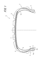
- FIG. 1 is a tire width direction sectional view showing a run flat tire according to an embodiment of the present invention.
- FIG. 2 is a cross-sectional view in the tire width direction showing an enlargement of the periphery of a bead portion of the run flat tire of FIG. 1.
- FIG. 1 is a cross-sectional view in the tire width direction showing a run-flat tire 1 (hereinafter also simply referred to as “tire”) according to an embodiment of the present invention in an unloaded state without being mounted on an applied rim.
- the run flat tire 1 adjusts the interval of each bead portion 2 to be described later to the interval when the bead portion 2 is attached to the applicable rim, and contacts the rim flange when each bead portion 2 is attached to the applicable rim.
- the bead back surface Po which becomes the outer surface of the portion 2 is in a state of being perpendicular to the tire width direction.
- the run-flat tire 1 shown in FIG. 1 is a so-called run-flat tire 1 that can travel a certain distance without losing the load supporting ability even when the tire internal pressure is reduced by puncture or the like. 3, a pair of sidewall portions 4 that are continuous on both sides of the tread portion 3, and a bead portion 2 that is continuous with each sidewall portion 4. Further, the run-flat tire 1 includes a carcass main body portion that extends in a toroidal manner between the bead cores 5 embedded in each bead portion 2 over the tread portion 3, the sidewall portion 4, and the bead portion 2, and the carcass main body portion.
- the carcass 6 is located on the outer side in the tire width direction and includes a carcass folding portion that extends from the carcass main body portion and is folded around the bead core 5 from the inner side in the tire radial direction toward the outer side in the tire radial direction. .
- FIG. 1 shows a case where the belt 7 is composed of a total of three belt layers, in the run-flat tire 1 of the present invention, the number of belt layers and the arrangement position thereof are arbitrary as required. The number of layers and the arrangement position can be set.
- the bead core 5 embedded in the bead portion 2 is sandwiched between the carcass main body portion and the carcass folding portion located on the outer side in the tire width direction of the carcass main body portion.
- a bead filler 8 having a substantially triangular cross section is disposed along the carcass 6 such that the thickness gradually decreases toward the outer side in the tire radial direction.
- the carcass 6 in the side wall portion 4 is arranged on the inner side in the tire width direction, specifically, on the carcass 6 in the region extending from the tire width direction end portion of the tread portion 3 to the bead portion 2 and on the tire inner surface side of the carcass 6.
- a side reinforcing rubber 10 having a substantially crescent-shaped cross section made of rubber having a relatively high elastic modulus is disposed between the inner liner 9 provided.
- the side reinforcing rubber 10 may be disposed outside the carcass 6, or may be disposed between the carcass layers when two carcass layers forming the carcass 6 are provided.
- the bead portion 2 is formed with curved outer contour lines of the bead heel 2h and the bead toe 2t in a cross-sectional view in the tire width direction. Further, the bead heel 2h of the bead portion 2 is located on the outer side in the tire radial direction than the bead toe 2t.
- the outer contour line of the bead heel 2h or the bead toe 2t can be formed to be square.
- the inventors conducted sincere research on the method of securing the resistance to rim detachment while maintaining the durability of the side reinforcing rubber of the run flat tire, and obtained the following knowledge. That is, the improvement of the rim resistance of the run-flat tire can be realized by increasing the tightening of the bead portion to the rim. On the other hand, if the tightening to the rim is increased, the bead part is excessively fixed to the rim, and when the lateral force is applied during run flat running, the movement of the bead part in the rim is suppressed.
- the diameter Dc of the inner end in the tire radial direction of the bead core 5 is 3.0 to larger than the rim diameter Dr of the applied rim in the tire width direction sectional view.
- the diameter Dh of the bead heel point Ih is 4.5 mm larger, and is 1.7 to 2.9 mm smaller than the rim diameter Dr.
- the bead core 2 is strongly fixed to the rim by increasing the diameter Dc of the bead core 5 within a range of 4.5 mm or less with respect to the rim diameter Dr of the applied rim, and the rim seat Since the contact pressure of the bead base surface Pb of the bead part 2 with respect to is improved, even if a lateral force is applied during the run-flat running, the positional deviation of the bead part 2 can be suppressed. Further, by setting the diameter Dc to be larger than the rim diameter Dr by 3.0 mm or more, even if a lateral force is applied during run-flat traveling, the bead portion 2 is not fixed to the rim excessively. Therefore, it is possible to prevent concentration of strain on the side reinforcement rubber 10 and therefore, the durability of the side reinforcing rubber 10 is not lowered.
- the bead heel 2h side portion of the bead portion 2 is strongly fixed to the rim, and the bead with respect to the rim seat is Since the contact pressure at the bead heel 2h side portion of the base surface Pb is improved, even if a lateral force is applied during the run-flat running, the positional deviation of the bead portion 2 can be sufficiently suppressed. As a result, sufficient rim detachment resistance can be ensured.
- the bead portion 2 is not excessively fixed to the rim.
- the concentration of strain on the reinforcing rubber 10 can be prevented, and therefore the durability of the side reinforcing rubber 10 is not lowered.
- the diameter Dc is a rim in a cross-sectional view in the tire width direction. More preferably, the diameter Dr is 3.0 to 4.2 mm larger than the diameter Dr, and the diameter Dh is 2.0 to 2.9 mm smaller than the rim diameter Dr.
- the section height is less than 120 mm, More preferably, the diameter Dc is 3.3 to 4.5 mm larger than the rim diameter Dr, and the diameter Dh is 1.7 to 2.6 mm smaller than the rim diameter Dr.
- “Section height” refers to a value obtained by multiplying “nominal width of tire cross section” by “nominal size of tire flatness”.
- the operation of mounting the run-flat tire on the rim is to place each bead part over the rim flange of the rim, once positioned in the well inside the rim hump, and then raised to a predetermined internal pressure of the tire. Then, the bead portion is carried over the rim hump so as to be positioned on the rim seat at a predetermined position.
- the rim flange or the rim hump over the bead portion when the rim is assembled is compared with a normal pneumatic tire. As a result, rim assembly tends to be difficult, and it is required that the rim assembly performance does not deteriorate.
- the outer contour line of the bead heel 2h of the bead portion 2 is formed from one arc in the tire width direction cross-sectional view, and the end E of the arc on the bead base surface Pb side.
- the bead core 5 is located on the inner side in the tire width direction than the position in the tire width direction at the outer end in the tire width direction. According to this, since the corner is eliminated by forming the outer contour line of the bead heel 2h from one arc, the rim assembly can be smoothly performed without being caught by the rim hump or the like.
- the rubber volume forming the bead heel 2h can be suppressed by positioning the end E of the arc on the inner side in the tire width direction than the outer end in the tire width direction of the bead core 5. As a result, the rim assembly property can be sufficiently maintained.
- the rubber flow of the bead portion 2 becomes smooth during vulcanization of the tire, and manufacturing defects can be reduced.
- the diameter Dc is 3.0 to 4.5 mm larger than the rim diameter Dr and the diameter Dh is larger than the rim diameter Dr in the tire width direction sectional view. Also, the rim assembly property can be maintained by reducing the diameter by 1.7 to 2.9 mm.
- the radius of curvature of the arc is preferably 5.0-8. 0 mm.
- the radius of curvature of the arc is preferably 5.0-8. 0 mm.
- the straight line connecting the bead heel point Ih and the bead toe point It has an angle ⁇ in the range of 12.2 to 14.7 ° with respect to the tire width direction. Just tilted. According to this, even if a lateral force is applied during run flat traveling, it is possible to improve the rim detachment resistance while preventing the concentration of strain on the side reinforcing rubber 10. That is, when the angle ⁇ is set to 12.2 ° or more, the contact pressure with respect to the rim of the bead toe 2t side portion of the bead portion 2 is increased. Can be sufficiently suppressed, and as a result, rim detachment resistance can be improved.
- the contact pressure on the bead toe 2t side portion does not become excessive, and therefore the bead portion 2 is not fixed to the rim, so that the distortion to the side reinforcing rubber 10 is reduced. Concentration can be prevented, and as a result, a decrease in durability of the side reinforcing rubber 10 can be effectively prevented.
- the angle ⁇ is 12. More preferably, it is in the range of 5 to 14.7 °, and when the section height is less than 120 mm, the angle ⁇ is in the range of 12.2 to 14.4 ° in a cross-sectional view in the tire width direction. More preferred.
- the outer contour of the bead base corresponding to the bead base surface Pb out of the outer contour of the bead portion 2 is a straight line in the tire width direction sectional view.
- a bead toe side portion 22 and a bead toe side portion 22 connected to the bead toe side portion 22 at a connecting point Ic are provided.
- the bead toe side portion 22 is 17.5 to Preferably, it is inclined by an angle ⁇ of 19.5 °.
- each inclination of the bead heel side part 21 and the bead toe side part 22 is different.
- a part of the curved portion 23 forming the outer contour line of the bead heel 2h is the bead heel side portion 21, and the end E of the curved portion 23 of the bead heel 2h (the outer contour of the bead heel 2h).
- the end E) of the line on the bead base surface Pb side is the connection point Ic
- the bead toe side portion 22 is inclined from the connection point Ic to the inside in the tire radial direction and before the curved portion 24 of the bead toe 2t.
- it protrudes toward the tire radial direction outer side at the connection point Ic.
- the bead toe point It is preferably located on the extension line of the bead toe side portion 22.
- the angle ⁇ is set to 17.5 ° or more, the contact pressure of the bead portion 2 with respect to the rim on the bead toe 2t side is increased, and even if a lateral force is applied during run flat running, the rim removal resistance is improved. It can be improved effectively.
- the angle ⁇ is not inclined too much, so that the rigidity of the bead toe 2t is increased, and when the tire 1 is mounted on the rim, for example, the bead portion 2 is When the rim flange is climbed over, the bead toe 2t smoothly climbs over the rim flange to reduce the amount of biting, so that damage such as chipping of the tip of the bead toe 2t does not occur (that is, the rim assembly property is maintained).
- the angle ⁇ to 19.5 ° or less the contact pressure of the bead toe side portion 22 with respect to the rim is made uniform and the friction coefficient is improved. Therefore, even if a lateral force is applied during run flat running, The detachability can be effectively improved.
- the angle ⁇ is 18.0 to 19 when the section height is 120 mm or more. More preferably, the angle ⁇ is 17.5 to 19.0 ° when the section height is less than 120 mm.
- a part of the curved portion 23 forming the outer contour line of the bead heel 2 h is a bead heel side portion 21, but the bead base surface on the inner side in the tire width direction than the curved portion 23.
- a bead heel side portion 21 and a connection point Ic can be provided on Pb separately from the curved portion 23 and its end E. In such a case, when the bead heel side portion 21 is linear, it is preferable that the inclination of the bead heel side portion 21 with respect to the tire width direction is less than 17.5 °.
- the connecting point Ic is preferably located within the range of the position of the bead core 5 in the tire width direction, in other words, the inside of the bead core 5 in the tire radial direction.
- the contact pressure with respect to the rim of the bead portion 2 changes on the bead heel 2h side and the bead toe 2t side with the connection point Ic as a boundary, but by positioning the connection point Ic on the inner side in the tire radial direction of the bead core 5 having high rigidity, The non-uniformity of the contact pressure can be reduced.
- the connecting point Ic is the end E of the curved portion 23 of the bead heel 2h.
- the connecting point Ic and the end E are different, the connecting point Ic from the same viewpoint. It is preferable that Ic and the end E are located inside the bead core 5 in the tire radial direction.
- the angle ⁇ of the bead toe point It is 30 ° or more. According to this, since the rigidity of the bead toe 2t is improved, for example, when the tire 1 is mounted on the rim, damage such as chipping of the bead toe 2t can be prevented.
- the angle ⁇ of the bead toe point It is in the range of 30 to 90 °.
- a textile chafer is disposed at least between the bead core 5 and the bead base surface Pb, although not shown.
- a reinforcing cord layer formed by covering a layer formed by arranging organic fiber cords with rubber can be used.
- the textile chafer one in which the cord is inclined at an angle of 30 to 60 °, preferably 45 ° with respect to the tire circumferential direction can be used.
- the tires of Examples 1 to 21 are run-flat tires of tire size 205 / 55R16 having side reinforcement rubber, and have the configurations shown in FIGS. 1 and 2 according to the specifications shown in Table 1.
- the tires of Comparative Examples 1 to 4 are the same as the tires of Example 1 except that each configuration of the bead portion is different depending on the specifications shown in Table 1. The performance of such a test tire was evaluated by the following method. The results are shown in Table 1.
- Rim assembly test When mounting each test tire on a rim having a rim size of 6.5J-16, whether or not the bead toe was damaged was visually observed and evaluated. In addition, it was evaluated whether or not the bead part can get over the rim hump with the standard pressure applied when each test tire is mounted on the rim (meaning that the bead part cannot get over the rim hump in one operation, In that case, it is necessary to release the pressure and reapply the lubricant to the bead portion or rim). When the bead toe is not damaged, and when the bead portion can get over the rim hump and the tire can be attached to the rim at a normal pressure, it means that the rim assembly is good.
- Run flat turning test Each test tire was mounted on a rim similar to that described above, its internal pressure was 0 kPa, and the tire was attached to a vehicle having a weight of 2 t. Next, after running the vehicle for 5 km at a speed of 20 km / h and running-in, the vehicle enters the turning circuit with a radius of 25 m at a predetermined speed, and stops when the turning circuit has made a 1/3 turn. It was. At this time, if the tire does not come off the rim even if the vehicle is driven twice on the turning circuit, or if the side reinforcing rubber of the tire is not damaged (that is, the vehicle can run), the speed is 1 km / h. I went up and made it run in the same way. Then, the speed (turning limit) when either the rim disengagement or the side reinforcing rubber was damaged was measured. The higher the speed is, the more the rim resistance is secured while maintaining the durability of the side reinforcing rubber for the tire.
- the tires of Examples 1 to 21 have a higher limit speed in the turning circuit in the run-flat turning test than the tires of Comparative Examples 1 to 4, that is, the durability of the side reinforcing rubber is maintained. However, it was found that sufficient rim detachment resistance can be secured even during run-flat driving. Note that the tire of Example 21 was not subjected to the run-flat turning test because the bead toe was damaged in the rim assembly test.
Landscapes
- Engineering & Computer Science (AREA)
- Mechanical Engineering (AREA)
- Tires In General (AREA)
Abstract
サイド補強ゴムの耐久性を維持しつつ、ランフラット走行時でも十分な耐リム外れ性を確保することが可能なランフラットタイヤ(1)を提供することを目的とする。この発明のランフラットタイヤ(1)は、トレッド部と、該トレッド部の両側に連なる一対のサイドウォール部と、各サイドウォール部に連なるビード部(2)と、該ビード部(2)に埋設されたビードコア(5)と、前記サイドウォール部に配設される断面三日月状のサイド補強ゴムと、を備えてなるランフラットタイヤ(1)であって、タイヤ幅方向断面視において、前記ビードコア(5)のタイヤ径方向内端の径(Dc)が、前記リム径(Dr)よりも3.0~4.5mm大きく、前記ビード部(2)のビードヒール点(Ih)の径(Dh)が、適用リムのリム径(Dr)よりも1.7~2.9mm小さいことを特徴とする。
Description
本発明はランフラットタイヤに関する。
タイヤのパンク等によってタイヤ内圧が低下した場合であっても、荷重支持能力を失うことなくある程度の距離の走行が可能な、所謂ランフラットタイヤとして、比較的弾性率が高い断面三日月状のサイド補強ゴムをタイヤのサイドウォール部のカーカスのタイヤ内面側に配設して、サイドウォール部の剛性を向上させたサイド補強型のランフラットタイヤが各種提案されている。
ここで、サイド補強型のランフラットタイヤでは、ランフラット走行時(タイヤパンク時等のタイヤ内圧が大幅に低下した状態での走行時)において、車両が直進するときにはサイド補強ゴムによってタイヤの撓み変形を大きくすることなく走行可能であるが、車両が旋回すると、その旋回によってタイヤに対して横力が加わるので、タイヤが特にタイヤ幅方向に大きく変形する。そして、横力によってタイヤの変形が生じると、タイヤのビード部が、サイドウォール部とともに旋回中心側に引っ張られるので、ビード部がリムハンプを乗り越えてリムのウエルに落ち易い状態になったり、あるいは、ビード部がリムフランジを乗り越えやすい状態になったりするおそれがあり、その結果としてビード部がリムのリムシートから外れ易い傾向があった。
そこで、上記のようなビード部のリム外れの問題に対しては、タイヤに対して横力が加わってもビード部がリムハンプを乗り越えにくい特別の形状を有するリムを用いたり、あるいは、横力が加わってもビード部がリムシートから外れるのを抑制させたタイヤ、例えばビード部に埋設したビードコアの、ビード部内の位置を規定したタイヤ(例えば、特許文献1)等が提案されている。
ところで、上述の特別の形状を有するリムは、ランフラットタイヤを利用するユーザーが当該リムを所有していない場合には、ランフラットタイヤとともに新規に当該リムを購入することを要するため、ユーザーにとって金銭的な負担が発生するとともに、それまで使用していたリムが不要になることがあり、資源の有効活用の面からデメリットもある。
また、特許文献1に記載されるようなランフラットタイヤでは、ビード部がリムシートから外れるのを防止することが可能であるものの、さらに高い耐リム外れ性が要求されていた。また一方で、ランフラットタイヤにおいて耐リム外れ性を過剰に向上させすぎると、ビード部がリムに強く固定されてランフラット走行時にビード部のリム内でのわずかな動きも抑制されることとなって、ビード部のタイヤ径方向外側に配置されたサイド補強ゴムに歪が生じやすくなり、その結果としてサイド補強ゴムの耐久性が低下するなどの問題が生じる可能性があることがわかった。
そこで、本発明は、サイド補強ゴムの耐久性を維持しつつ、ランフラット走行時でも十分な耐リム外れ性を確保することが可能なランフラットタイヤを提供することを目的とする。
本発明のランフラットタイヤは、タイヤ幅方向断面視において、ビードコアのタイヤ径方向内端の径が、適用リムのリム径よりも3.0~4.5mm大きく、ビードヒール点を、ビード部のビードヒールの外輪郭線が曲線で形成される場合には、該ビードヒールの外輪郭線のビードベース面側の端での該外輪郭線の接線と、前記ビードヒールの外輪郭線のビード背面側の端での該外輪郭線の接線との交点とし、また、ビードヒールの外輪郭線が角張って形成される場合には、前記ビードヒールの外輪郭線のビードベース面側の該外輪郭線と、前記ビードヒールの外輪郭線のビード背面側の該外輪郭線とが交差する頂点(つまり、ビードヒールの外輪郭線でその角張った点)とするとき、前記ビードヒール点の径が、前記リム径よりも1.7~2.9mm小さいことを特徴とする。この構成によれば、サイド補強ゴムの耐久性を維持しつつ、ランフラット走行時でも十分な耐リム外れ性を確保することができる。
なお、本発明において、タイヤの構成部材の角度等および諸寸法等は、特に断りのない限り、タイヤを適用リムに装着せずかつ無負荷状態とし、さらに、各ビード部の間隔を適用リムに装着した場合の間隔に合わせるとともに、各ビード部を適用リムに取り付けた場合にリムフランジに接触することとなる、ビード部のタイヤ幅方向外側面であるビード背面を、タイヤ幅方向に対して垂直にした状態で測定するものとする。因みに、「適用リム」とは、産業規格であるJATMA(日本自動車タイヤ協会)YEAR BOOKに記載されている、適用サイズにおける標準リムを指す。
また、本発明において、「ビードコアのタイヤ径方向内端」とは、ビードコアを構成するコードで最もタイヤ径方向内側に位置するコードのタイヤ径方向内端を指すものとする。
また、本発明において、「ビードベース面」とは、適用リムに装着した場合に、適用リムのビードシートに接触するビード部のタイヤ径方向内周面を指し、「ビード背面」とは、適用リムに装着した場合に、リムフランジに接触するビード部のタイヤ幅方向外側面を指す。
さらに、本発明において、「点」の径および「端」の径とは、「点」および「端」を、タイヤ周方向に連結して形成される円の径を指す。
ここで、本発明のランフラットタイヤでは、タイヤ幅方向断面視において、前記ビードヒールの外輪郭線が、1つの円弧から形成され、前記円弧のビードベース面側の端が、前記ビードコアのタイヤ幅方向外端のタイヤ幅方向位置よりもタイヤ幅方向内側に位置することが好ましい。これによれば、タイヤを適用リムに装着する際のリム組み性を十分に維持することができる。
また、本発明のランフラットタイヤでは、タイヤ幅方向断面視において、ビードトウ点を、前記ビード部のビードトウの外輪郭線が曲線で形成される場合には、該ビードトウの外輪郭線のビードベース面側の端でのビードベース面の延長直線と、前記ビードトウの外輪郭線のビード内面側の端でのビード内面の延長直線との交点とし、また、ビードトウの外輪郭線が角張って形成される場合には、該ビードトウの外輪郭線のビードベース面側の該外輪郭線と、前記ビードトウの外輪郭線のビード内面側の該外輪郭線とが交差する頂点(つまり、ビードトウの外輪郭線でその角張った点)とするとき、前記ビードヒール点と、前記ビードトウ点とを結んだ直線が、タイヤ幅方向に対して12.2~14.7°傾斜することが好ましい。これによれば、サイド補強ゴムの耐久性の低下を効果的に防止しつつ、耐リム外れ性をより向上させることができる。
また、本発明において、「ビードトウ」とは、ビード部で最もタイヤ幅方向内側に位置する部分を指す。また、本発明において、「ビード内面」とは、ビード部の、タイヤの内腔側を向く表面を指す。
ここで、本発明のランフラットタイヤでは、タイヤ幅方向断面視において、前記ビード部の外輪郭線のうちビードベース面に相当するビードベースの外輪郭線が、直線状のビードトウ側部と、該ビードトウ側部と連結点で連結される、曲線状または前記ビードトウ側部の傾きと異なる傾きの直線状のビードヒール側部とを備え、前記ビードトウ側部が、タイヤ幅方向に対して、17.5~19.5°傾斜していることが好ましい。これによれば、タイヤを適用リムに装着する際のリム組み性をより十分に維持しつつ、耐リム外れ性をさらに向上させることができる。
さらに、本発明のランフラットタイヤでは、タイヤ幅方向断面視において、前記ビードトウ点を挟む前記ビード部の外輪郭線の角度(以下、「ビードトウ点の角度」ともいう。)が、30°以上であることが好ましい。これによれば、ビードトウの剛性が維持されて、タイヤを適用リムに装着する際のビードトウの損傷を防止することができる。なお、本発明において、「ビードトウ点を挟むビード部の外輪郭線の角度」とは、ビードトウの外輪郭線が曲線で形成される場合には、ビードトウ点を頂点として、ビードトウの外輪郭線のビードベース面側の端でのビードベース面の延長直線と、ビードトウの外輪郭線のビード内面側の端でのビード内面の延長直線と、で挟まれる角度、または、ビードトウの外輪郭線が角張って形成される場合には、ビードトウ点を頂点として、ビードベース面側の外輪郭線とビード内面側の外輪郭線とで挟まれる角度を指す。
さらに、本発明のランフラットタイヤでは、少なくとも前記ビードコアと前記ビード部のビードベース面との間に、テキスタイルチェーファーが配設されることが好ましい。これによれば、耐リム外れ性を十分に向上させることができる。
本発明によれば、サイド補強ゴムの耐久性を維持しつつ、ランフラット走行時でも十分な耐リム外れ性を確保することが可能なランフラットタイヤを提供することができる。
以下、図面を参照して本発明の一実施形態を詳細に例示説明する。
図1は、本発明の一実施形態に係るランフラットタイヤ1(以下、単に「タイヤ」ともいう。)を、適用リムに装着しない、無負荷の状態で示すタイヤ幅方向断面図である。なお、ランフラットタイヤ1は、後述の各ビード部2の間隔を適用リムに装着した場合の間隔に合わせるとともに、各ビード部2を適用リムに取り付けた場合にリムフランジに接触することとなるビード部2の外側面となるビード背面Poを、タイヤ幅方向に対して垂直にした状態となっている。
図1は、本発明の一実施形態に係るランフラットタイヤ1(以下、単に「タイヤ」ともいう。)を、適用リムに装着しない、無負荷の状態で示すタイヤ幅方向断面図である。なお、ランフラットタイヤ1は、後述の各ビード部2の間隔を適用リムに装着した場合の間隔に合わせるとともに、各ビード部2を適用リムに取り付けた場合にリムフランジに接触することとなるビード部2の外側面となるビード背面Poを、タイヤ幅方向に対して垂直にした状態となっている。
図1に示すランフラットタイヤ1は、パンク等によってタイヤ内圧が低下した場合であっても、荷重支持能力を失うことなくある程度の距離の走行が可能な、所謂ランフラットタイヤ1であり、トレッド部3と、トレッド部3の両側に連なる一対のサイドウォール部4と、各サイドウォール部4に連なるビード部2とを備えている。さらに、ランフラットタイヤ1は、各ビード部2内に埋設されたビードコア5の間を、トレッド部3、サイドウォール部4およびビード部2にわたってトロイド状に延在するカーカス本体部と、カーカス本体部のタイヤ幅方向外側に位置し、カーカス本体部から延びビードコア5の周りをタイヤ径方向内側からタイヤ径方向外側へ向かって折り返されてなるカーカス折返し部とから構成されるカーカス6を有している。
さらに、トレッド部3のカーカス6のタイヤ径方向外側には、それぞれゴム引きコード層からなる3枚のベルト層を積層してなるベルト7が配設されている。また、ベルト7のタイヤ径方向外側には、トレッドゴムが配設されており、トレッドゴムの表面には、タイヤ周方向に延びる周方向溝等のトレッド溝が形成されている。なお、図1では、ベルト7が、合計3層のベルト層からなる場合を示しているが、本発明のランフラットタイヤ1では、ベルト層の層数や配設位置は、必要に応じて任意の層数や配設位置とすることができる。
また、図1および2に示すように、ビード部2に埋設されたビードコア5のタイヤ径方向外側には、カーカス本体部と、カーカス本体部のタイヤ幅方向外側に位置するカーカス折返し部とに挟まれ、カーカス6に沿ってタイヤ径方向外側に向けて厚みが漸減する断面略三角形のビードフィラー8が配設されている。
さらに、サイドウォール部4におけるカーカス6のタイヤ幅方向内側に、具体的にはトレッド部3のタイヤ幅方向端部からビード部2にわたる領域の、カーカス6と、該カーカス6のタイヤ内面側に配設されたインナーライナー9との間に、比較的弾性率が高いゴムよりなる断面略三日月状のサイド補強ゴム10が配設されている。なお、サイド補強ゴム10は、図示しないが、カーカス6の外側に配設し、あるいはカーカス6を形成するカーカス層を2枚とした場合にはカーカス層の間に配設してもよい。
また、本実施形態では、ビード部2は、図2に示すように、タイヤ幅方向断面視で、ビードヒール2hおよびビードトウ2tの外輪郭線が曲線で形成されている。また、ビード部2のビードヒール2hはビードトウ2tよりもタイヤ径方向外側に位置している。なお、ビードヒール2hまたはビードトウ2tの外輪郭線が角張って形成されることも可能である。
ところで、発明者らは、ランフラットタイヤの、サイド補強ゴムの耐久性を維持しつつ、耐リム外れ性を確保する方途を誠意研究したところ、次の知見を得た。すなわち、ランフラットタイヤの耐リム外れ性の向上は、ビード部の、リムへの締め付けを大きくすれば実現できる。その一方で、リムへの締め付けを大きくすると、ビード部がリムに対して過剰に固定されて、ランフラット走行時に横力が加わった際に、ビード部のリム内での動きが抑制されるため、リムフランジと路面との間に挟まれて撓み変形したサイド補強ゴムのタイヤ径方向内側部分が大きく屈曲して、サイド補強ゴムに歪が集中する傾向があり、その結果として、サイド補強ゴムに割れ等が発生し、サイド補強ゴムの耐久性が低下するおそれがある。
そこで、本発明のランフラットタイヤ1では、図2に示すように、タイヤ幅方向断面視において、ビードコア5のタイヤ径方向内端の径Dcが、適用リムのリム径Drよりも3.0~4.5mm大きく、ビードヒール点Ihの径Dhが、リム径Drよりも1.7~2.9mm小さくなっている。
この構成によれば、ビードコア5の径Dcを、適用リムのリム径Drに対して4.5mm以下の範囲で大径にすることで、ビード部2がリムに対して強く固定されて、リムシートに対するビード部2のビードベース面Pbの接触圧が向上するので、ランフラット走行時に横力が加わっても、ビード部2の位置ずれを抑制することができる。また、径Dcをリム径Drに対して3.0mm以上大径にすることにより、ランフラット走行時に横力が加わっても、ビード部2がリムに対して固定され過ぎないので、サイド補強ゴム10への歪の集中を防止でき、それゆえにサイド補強ゴム10の耐久性を低下させることがない。
さらに、ビードヒール点Ihの径Dhを、適用リムのリム径Drに対して1.7mm以上小径にすることで、ビード部2のビードヒール2h側部分がリムに対して強く固定されて、リムシートに対するビードベース面Pbの当該ビードヒール2h側部分の接触圧が向上するので、ランフラット走行時に横力が加わっても、ビード部2の位置ずれを十分に抑制できる。その結果として、十分な耐リム外れ性を確保することができる。また、径Dhをリム径Drに対して2.9mm以下の範囲で小径にすることで、ランフラット走行時に横力が加わっても、ビード部2がリムに対して固定され過ぎないので、サイド補強ゴム10への歪の集中を防止でき、それゆえにサイド補強ゴム10の耐久性を低下させることがない。
なお、サイド補強ゴム10への歪の集中を防止しつつ、十分な耐リム外れ性を確保する観点からは、セクションハイトが120mm以上の場合には、タイヤ幅方向断面視において、径Dcがリム径Drよりも3.0~4.2mm大きく、径Dhがリム径Drよりも2.0~2.9mm小さいことがより好ましく、セクションハイトが120mm未満の場合には、タイヤ幅方向断面視において、径Dcがリム径Drよりも3.3~4.5mm大きく、径Dhがリム径Drよりも1.7~2.6mm小さいことがより好ましい。なお、「セクションハイト」とは、「タイヤの断面幅の呼び」と「タイヤの扁平率の呼び」とを掛け合わせた値を指す。
ここで、ランフラットタイヤをリムに装着する操作は、それぞれのビード部を、リムのリムフランジを乗り越えさせて、一旦、リムハンプより内側のウエルに位置させ、次いで、タイヤの所定の内圧に上昇させて、そのビード部を、リムハンプを乗り越えさせて所定の位置のリムシートに位置するように実施する。このように、サイドウォール部に配置した高弾性率のサイド補強ゴムを有するランフラットタイヤでは、リム組み際して上記のビード部のリムフランジの乗越えまたはリムハンプの乗越えが通常の空気入りタイヤと比してリム組みが困難になる傾向が有るので、リム組み性が低下しないことが求められる。
したがって、上記の観点から、図2に示すように、タイヤ幅方向断面視において、ビード部2のビードヒール2hの外輪郭線が、1つの円弧から形成され、円弧のビードベース面Pb側の端Eが、ビードコア5のタイヤ幅方向外端のタイヤ幅方向位置よりもタイヤ幅方向内側に位置することが好ましい。これによれば、ビードヒール2hの外輪郭線を1つの円弧から形成することにより角がなくなるので、リム組みを、リムハンプ等に引っかかることなく滑らかに行うことができる。また、円弧のビードベース面側の端を、ビードコアのタイヤ幅方向外端よりもタイヤ幅方向外側に位置させると、ビードヒールを形成するゴムボリュームが大きくなり、ビードヒールがリムハンプを滑らかに乗り越えにくくなる虞があるところ、円弧の端Eを、ビードコア5のタイヤ幅方向外端よりもタイヤ幅方向内側に位置させることにより、ビードヒール2hを形成するゴムボリュームを抑えることができる。その結果としてリム組み性を十分に維持することができる。そして、外輪郭線を円弧で形成することにより、タイヤ加硫時にビード部2のゴムの流動がスムーズになり製造不良を低下させることができる。なお、本発明のランフラットタイヤ1では、先述のように、タイヤ幅方向断面視において、径Dcを、リム径Drよりも3.0~4.5mm大きくし、径Dhを、リム径Drよりも1.7~2.9mm小さくすることによっても、リム組み性を維持することができる。
なお、ビードヒール2hの外輪郭線は、タイヤ幅方向断面視で、ビードヒール2hの外輪郭線が1つの円弧により形成される場合には、好ましくは、当該円弧の曲率半径は5.0~8.0mmである。円弧の曲率半径を5.0mm以上にすることによりリム組み性を十分に維持することができる。また、ビードヒールを形成するゴムボリュームが小さくなると、耐リム外れ性が低下する虞があるところ、曲率半径を8.0mm以下にすることにより、ビードヒール2hを形成するゴムボリュームが小さくなることを防止することができ、それゆえに十分な耐リム外れ性を確保することができる。
ここで、このランフラットタイヤ1では、図2に示すように、ビードヒール点Ihとビードトウ点Itとを結んだ直線が、タイヤ幅方向に対して12.2~14.7°の範囲の角度αだけ傾斜している。これによれば、サイド補強ゴム10への歪の集中を防止しつつ、ランフラット走行時に横力が加わっても、耐リム外れ性を向上させることができる。すなわち、角度αを12.2°以上にすることにより、ビード部2のビードトウ2t側部分のリムに対する接触圧が大きくなるので、ランフラット走行時に横力が加わっても、ビード部2の位置ずれを十分に抑制でき、その結果として、耐リム外れ性を向上させることができる。また、角度αを14.7°以下にすることにより、ビードトウ2t側部分の接触圧が過剰になりすぎず、それゆえにビード部2がリムに固定されすぎないので、サイド補強ゴム10への歪の集中を防止することができ、その結果としてサイド補強ゴム10の耐久性の低下を効果的に防止することができる。
なお、サイド補強ゴム10への歪の集中を防止しつつ、耐リム外れ性を向上させる観点からは、セクションハイトが120mm以上の場合には、タイヤ幅方向断面視において、角度αが、12.5~14.7°の範囲であることがより好ましく、セクションハイトが120mm未満の場合には、タイヤ幅方向断面視において、角度αが、12.2~14.4°の範囲であることがより好ましい。
また、このランフラットタイヤ1では、図2に示すように、タイヤ幅方向断面視において、ビード部2の外輪郭線のうちビードベース面Pbに相当するビードベースの外輪郭線が、直線状のビードトウ側部22と、ビードトウ側部22と連結点Icで連結される、曲線状または直線状のビードヒール側部21とを備え、ビードトウ側部22が、タイヤ幅方向に対して、17.5~19.5°の角度βだけ傾斜していることが好ましい。なお、ビードヒール側部21が直線状の場合は、ビードヒール側部21とビードトウ側部22とのそれぞれの傾きが異なっている。そして本実施形態では、図示するように、ビードヒール2hの外輪郭線をなす曲線状部分23の一部がビードヒール側部21であり、ビードヒール2hの曲線状部分23の端E(ビードヒール2hの外輪郭線のビードベース面Pb側の端E)が連結点Icであり、連結点Icからタイヤ径方向内側に傾斜してビードトウ2tの曲線状部分24前までがビードトウ側部22である。また、この実施形態では、連結点Icで、タイヤ径方向外側に向かって凸となっている。なお、ビードトウ側部22の延長線上に、ビードトウ点Itが位置することが好ましい。
これによれば、角度βを17.5°以上にすることにより、ビード部2のビードトウ2t側のリムに対する接触圧が大きくなり、ランフラット走行時に横力が加わっても、耐リム外れ性を効果的に向上させることができる。また、角度βを19.5°以下にすることにより、ビードトウ側部22の傾斜が大きくなりすぎないので、ビードトウ2tの剛性が上がり、タイヤ1をリムに装着する際、例えばビード部2を、リムフランジを乗り越えさせるときに、ビードトウ2tがリムフランジを滑らかに乗越えることで食い込み量が減る為、ビードトウ2tの先端が欠ける等の損傷が発生しない(すなわちリム組性が維持されている)。また、角度βを19.5°以下にすることにより、ビードトウ側部22の、リムに対する接地圧が均一化されて摩擦係数が向上するので、ランフラット走行時に横力が加わっても、耐リム外れ性を効果的に向上させることができる。
なお、耐リム外れ性を向上させつつ、リム組み性を向上させてリム組時のビード部の損傷を防ぐ観点からは、セクションハイト120mm以上の場合には、角度βが、18.0~19.5°であることがより好ましく、セクションハイト120mm未満の場合には、角度βが、17.5~19.0°であることがより好ましい。
またなお、図2に示すビード部2は、ビードヒール2hの外輪郭線をなす曲線状部分23の一部をビードヒール側部21としているが、曲線状部分23よりもタイヤ幅方向内側のビードベース面Pb上に、曲線状部分23およびその端Eとは別にビードヒール側部21および連結点Icを設けることができる。なお、かかる場合であって、ビードヒール側部21が直線状のときは、ビードヒール側部21のタイヤ幅方向に対する傾きが、17.5°未満であることが好ましい。
さらに、連結点Icは、ビードコア5のタイヤ幅方向位置の範囲内に、言い換えればビードコア5のタイヤ径方向内側に位置することが好ましい。ビード部2のリムに対する接触圧が、連結点Icを境にしてビードヒール2h側およびビードトウ2t側で変化するが、連結点Icを剛性の高いビードコア5のタイヤ径方向内側に位置させることにより、上記の接触圧の不均一を低減させることができる。なお、本実施形態では、図2に示すように、連結点Icが、ビードヒール2hの曲線状部分23の端Eであるが、連結点Icと端Eとが異なる場合、同様な観点から連結点Icと端Eとはビードコア5のタイヤ径方向内側に位置していることが好ましい。
ここで、ビードトウ点Itの角度γが、30°以上であることが好ましい。これによれば、ビードトウ2tの剛性が向上するので、例えばタイヤ1をリムに装着する際に、ビードトウ2tが欠ける等の損傷を防止することができる。
なお、製造上の観点からは、ビードトウ点Itの角度γが、30~90°の範囲であることがより好ましい。
ところで、ビード部2の、ビードコア5よりもタイヤ径方向内側部分の剛性を向上させることで、ランフラット走行時に横力が加わっても耐リム外れ性を向上させることができるところ、本発明のランフラットタイヤ1では、少なくともビードコア5とビードベース面Pbとの間に、図示しないがテキスタイルチェーファーが配設されることが好ましい。なお、テキスタイルチェーファーとしては、有機繊維コードを配列させてなる層をゴムで被覆して形成される補強コード層を用いることができる。また、テキスタイルチェーファーは、そのコードがタイヤ周方向に対して30~60°の角度、好ましくは45°の角度で傾斜するものを用いることができる。
以上、図面を参照して本発明の実施形態を例示説明したが、本発明のランフラットタイヤは、上記の例に限定されることは無く、適宜変更を加えることができる。
以下、実施例により本発明を更に詳細に説明するが、本発明は下記の実施例になんら限定されるものではない。
実施例1~21のタイヤは、サイド補強ゴムを有するタイヤサイズ205/55R16のランフラットタイヤであって、表1に示す諸元で、図1および2に示すような構成を有するものである。また、比較例1~4のタイヤは、ビード部の各構成を表1に示す諸元で異なる以外、実施例1のタイヤと同等なものである。このような供試タイヤについて、以下の方法で性能を評価した。結果を表1に示す。
リム組み性試験:各供試タイヤをリムサイズ6.5J-16のリムに装着する際に、ビードトウに損傷が発生するか否かを目視で観察して評価した。また、各供試タイヤをリムに装着する際に適用する標準圧力で、ビード部がリムハンプを乗り越えられるか否かを評価した(ビード部がリムハンプを一度の作業で乗り越えられない場合を意味し、その場合には、圧力を抜いて、ビード部やリムに潤滑剤を再塗布する必要が生じる)。ビードトウに損傷が発生しない場合、および標準圧力で、ビード部がリムハンプを乗り越えてタイヤをリムに装着できた場合、リム組み性が良好であることを指す。
ランフラット旋回試験:各供試タイヤを、上述と同様なリムに装着しその内圧を0kPaにして、タイヤを重量2tの車両に取り付けた。次いで、車両を速度20km/hで5km走行させて慣らし運転をした後、車両を、半径25mの旋回路に所定の速度で進入させて、当該旋回路を1/3周走行させたところで停止させた。この時、車両を旋回路で2回走行させても、タイヤがリムから外れない、あるいは、タイヤのサイド補強ゴムが破損していない場合(すなわち走行可能な場合)には、速度を1km/h上げて、同様に旋回路を走行させた。そして、リム外れまたはサイド補強ゴムの破損のいずれかが生じたときの速度(旋回限界)を測定した。その速度が大きい程、そのタイヤについて、サイド補強ゴムの耐久性を維持しつつ、十分な耐リム外れ性を確保していることを示す。

表1より、実施例1~21のタイヤでは、比較例1~4のタイヤと比較して、ランフラット旋回試験における旋回路での限界速度が大きくなり、すなわち、サイド補強ゴムの耐久性を維持しつつ、ランフラット走行時でも十分な耐リム外れ性を確保することできることがわかった。
なお、実施例21のタイヤは、リム組み性試験において、ビードトウに損傷が生じたため、ランフラット旋回試験を実施していない。
なお、実施例21のタイヤは、リム組み性試験において、ビードトウに損傷が生じたため、ランフラット旋回試験を実施していない。
本発明によれば、サイド補強ゴムの耐久性を維持しつつ、ランフラット走行時でも十分な耐リム外れ性を確保することが可能なランフラットタイヤを提供することができる。
1 ランフラットタイヤ ; 2 ビード部 ; 21 ビードヒール側部 ; 22 ビードトウ側部 ; 23、24 曲線状部分 ; 2h ビードヒール ; 2t ビードトウ ; 3 トレッド部 ; 4 サイドウォール部 ; 5 ビードコア ; 6 カーカス ; 7 ベルト ; 8 ビードフィラー ; 9 インナーライナー ; 10 サイド補強ゴム ; Dc、Dh 径 ; Dr リム径 ; E 端 ; Ic 連結点 ; Ih ビードヒール点 ; It ビードトウ点 ; Pb ビードベース面 ; Po ビード背面 ; α、β、γ 角度
Claims (6)
- トレッド部と、該トレッド部の両側に連なる一対のサイドウォール部と、各サイドウォール部に連なるビード部と、該ビード部に埋設されたビードコアと、前記サイドウォール部に配設される断面三日月状のサイド補強ゴムと、を備えてなるランフラットタイヤであって、
タイヤ幅方向断面視において、
前記ビードコアのタイヤ径方向内端の径が、適用リムのリム径よりも3.0~4.5mm大きく、
ビードヒール点を、前記ビード部のビードヒールの外輪郭線が曲線で形成される場合には、該ビードヒールの外輪郭線のビードベース面側の端での該外輪郭線の接線と、前記ビードヒールの外輪郭線のビード背面側の端での該外輪郭線の接線との交点とし、また、ビードヒールの外輪郭線が角張って形成される場合には、前記ビードヒールの外輪郭線のビードベース面側の該外輪郭線と、前記ビードヒールの外輪郭線のビード背面側の該外輪郭線とが交差する頂点とするとき、
前記ビードヒール点の径が、前記リム径よりも1.7~2.9mm小さいことを特徴とする、ランフラットタイヤ。 - タイヤ幅方向断面視において、前記ビードヒールの外輪郭線が、1つの円弧から形成され、
前記円弧のビードベース面側の端が、前記ビードコアのタイヤ幅方向外端のタイヤ幅方向位置よりもタイヤ幅方向内側に位置することを特徴とする、請求項1に記載のランフラットタイヤ。 - タイヤ幅方向断面視において、
ビードトウ点を、前記ビード部のビードトウの外輪郭線が曲線で形成される場合には、該ビードトウの外輪郭線のビードベース面側の端でのビードベース面の延長直線と、前記ビードトウの外輪郭線のビード内面側の端でのビード内面の延長直線との交点とし、また、ビードトウの外輪郭線が角張って形成される場合には、該ビードトウの外輪郭線のビードベース面側の該外輪郭線と、前記ビードトウの外輪郭線のビード内面側の該外輪郭線とが交差する頂点とするとき、
前記ビードヒール点と、前記ビードトウ点とを結んだ直線が、タイヤ幅方向に対して12.2~14.7°傾斜することを特徴とする、請求項1または2に記載のランフラットタイヤ。 - タイヤ幅方向断面視において、前記ビード部の外輪郭線のうちビードベース面に相当するビードベースの外輪郭線が、直線状のビードトウ側部と、該ビードトウ側部と連結点で連結される、曲線状または前記ビードトウ側部の傾きと異なる傾きの直線状のビードヒール側部とを備え、
前記ビードトウ側部が、タイヤ幅方向に対して、17.5~19.5°傾斜していることを特徴とする、請求項1~3のいずれかに記載のランフラットタイヤ。 - タイヤ幅方向断面視において、前記ビードトウ点を挟む前記ビード部の外輪郭線の角度が、30°以上であることを特徴とする、請求項1~4のいずれかに記載のランフラットタイヤ。
- 少なくとも前記ビードコアと前記ビード部のビードベース面との間に、テキスタイルチェーファーが配設されることを特徴とする、請求項1~5のいずれかに記載のランフラットタイヤ。
Priority Applications (3)
| Application Number | Priority Date | Filing Date | Title |
|---|---|---|---|
| EP14800584.6A EP3000625B1 (en) | 2013-05-20 | 2014-05-19 | Run flat tire |
| CN201480029404.1A CN105228837B (zh) | 2013-05-20 | 2014-05-19 | 缺气保用轮胎 |
| US14/787,542 US20160121662A1 (en) | 2013-05-20 | 2014-05-19 | Run flat tire |
Applications Claiming Priority (2)
| Application Number | Priority Date | Filing Date | Title |
|---|---|---|---|
| JP2013106407A JP5809191B2 (ja) | 2013-05-20 | 2013-05-20 | 乗用車用のランフラットタイヤ |
| JP2013-106407 | 2013-05-20 |
Publications (1)
| Publication Number | Publication Date |
|---|---|
| WO2014188700A1 true WO2014188700A1 (ja) | 2014-11-27 |
Family
ID=51933267
Family Applications (1)
| Application Number | Title | Priority Date | Filing Date |
|---|---|---|---|
| PCT/JP2014/002629 Ceased WO2014188700A1 (ja) | 2013-05-20 | 2014-05-19 | ランフラットタイヤ |
Country Status (5)
| Country | Link |
|---|---|
| US (1) | US20160121662A1 (ja) |
| EP (1) | EP3000625B1 (ja) |
| JP (1) | JP5809191B2 (ja) |
| CN (1) | CN105228837B (ja) |
| WO (1) | WO2014188700A1 (ja) |
Cited By (1)
| Publication number | Priority date | Publication date | Assignee | Title |
|---|---|---|---|---|
| US20210339577A1 (en) * | 2020-04-30 | 2021-11-04 | Toyo Tire Corporation | Pneumatic tire |
Families Citing this family (5)
| Publication number | Priority date | Publication date | Assignee | Title |
|---|---|---|---|---|
| JP5809192B2 (ja) * | 2013-05-20 | 2015-11-10 | 株式会社ブリヂストン | 乗用車用のランフラットタイヤ |
| JP6763188B2 (ja) * | 2016-04-18 | 2020-09-30 | 住友ゴム工業株式会社 | 空気入りタイヤ |
| CN106739843A (zh) * | 2017-01-20 | 2017-05-31 | 安徽佳通乘用子午线轮胎有限公司 | 适用于5°斜底轮辋的全钢载重无内轮胎 |
| JP7367488B2 (ja) * | 2019-11-26 | 2023-10-24 | 住友ゴム工業株式会社 | 空気入りタイヤ |
| CN118219710A (zh) * | 2024-04-22 | 2024-06-21 | 肇庆骏鸿实业有限公司 | 一种防异响的缺气保用轮胎 |
Citations (4)
| Publication number | Priority date | Publication date | Assignee | Title |
|---|---|---|---|---|
| JP2001225614A (ja) * | 2000-02-15 | 2001-08-21 | Yokohama Rubber Co Ltd:The | 空気入りタイヤ |
| JP2002513361A (ja) * | 1997-06-10 | 2002-05-08 | ミシュラン ルシェルシュ エ テクニク ソシエテ アノニム | ビード/リム境界部を改良したランフラットタイヤ |
| JP2009126262A (ja) | 2007-11-21 | 2009-06-11 | Bridgestone Corp | ランフラットタイヤ |
| JP2010111173A (ja) * | 2008-11-04 | 2010-05-20 | Sumitomo Rubber Ind Ltd | ランフラットタイヤ |
Family Cites Families (10)
| Publication number | Priority date | Publication date | Assignee | Title |
|---|---|---|---|---|
| GB1436725A (en) * | 1972-06-21 | 1976-05-26 | Bridgestone Tire Co Ltd | Pneumatic safety tyre |
| IN155019B (ja) * | 1979-12-06 | 1984-12-22 | Dunlop Ltd | |
| US5217549A (en) * | 1991-04-04 | 1993-06-08 | Bridgestone/Firestone, Inc. | Pneumatic safety tire |
| CA2089450A1 (en) * | 1992-02-21 | 1993-08-22 | Masanao Yoshida | Pneumatic tire |
| JP2733730B2 (ja) * | 1992-12-28 | 1998-03-30 | 住友ゴム工業株式会社 | 空気入りタイヤ |
| JPH0920110A (ja) * | 1995-07-04 | 1997-01-21 | Bridgestone Corp | 空気入りラジアル・タイヤ |
| JP3485413B2 (ja) * | 1996-03-29 | 2004-01-13 | 住友ゴム工業株式会社 | 空気入りタイヤのビード部構造 |
| JPH1191321A (ja) * | 1997-09-25 | 1999-04-06 | Bridgestone Corp | 重荷重用空気入りタイヤ |
| JP5809192B2 (ja) * | 2013-05-20 | 2015-11-10 | 株式会社ブリヂストン | 乗用車用のランフラットタイヤ |
| JP6317130B2 (ja) * | 2014-02-20 | 2018-04-25 | 株式会社ブリヂストン | ランフラットタイヤ |
-
2013
- 2013-05-20 JP JP2013106407A patent/JP5809191B2/ja not_active Expired - Fee Related
-
2014
- 2014-05-19 CN CN201480029404.1A patent/CN105228837B/zh not_active Expired - Fee Related
- 2014-05-19 WO PCT/JP2014/002629 patent/WO2014188700A1/ja not_active Ceased
- 2014-05-19 EP EP14800584.6A patent/EP3000625B1/en not_active Not-in-force
- 2014-05-19 US US14/787,542 patent/US20160121662A1/en not_active Abandoned
Patent Citations (4)
| Publication number | Priority date | Publication date | Assignee | Title |
|---|---|---|---|---|
| JP2002513361A (ja) * | 1997-06-10 | 2002-05-08 | ミシュラン ルシェルシュ エ テクニク ソシエテ アノニム | ビード/リム境界部を改良したランフラットタイヤ |
| JP2001225614A (ja) * | 2000-02-15 | 2001-08-21 | Yokohama Rubber Co Ltd:The | 空気入りタイヤ |
| JP2009126262A (ja) | 2007-11-21 | 2009-06-11 | Bridgestone Corp | ランフラットタイヤ |
| JP2010111173A (ja) * | 2008-11-04 | 2010-05-20 | Sumitomo Rubber Ind Ltd | ランフラットタイヤ |
Cited By (1)
| Publication number | Priority date | Publication date | Assignee | Title |
|---|---|---|---|---|
| US20210339577A1 (en) * | 2020-04-30 | 2021-11-04 | Toyo Tire Corporation | Pneumatic tire |
Also Published As
| Publication number | Publication date |
|---|---|
| EP3000625B1 (en) | 2018-01-03 |
| JP5809191B2 (ja) | 2015-11-10 |
| JP2014226977A (ja) | 2014-12-08 |
| EP3000625A1 (en) | 2016-03-30 |
| CN105228837B (zh) | 2017-07-04 |
| EP3000625A4 (en) | 2016-06-01 |
| US20160121662A1 (en) | 2016-05-05 |
| CN105228837A (zh) | 2016-01-06 |
Similar Documents
| Publication | Publication Date | Title |
|---|---|---|
| CN101903196B (zh) | 充气轮胎 | |
| CN109562645B (zh) | 泄气保用轮胎 | |
| JP5091223B2 (ja) | 空気入りラジアルタイヤ | |
| JP5809191B2 (ja) | 乗用車用のランフラットタイヤ | |
| EP2949483B1 (en) | Pneumatic tire | |
| CN101541566A (zh) | 充气轮胎 | |
| CN106029405B (zh) | 缺气保用轮胎 | |
| JP5809192B2 (ja) | 乗用車用のランフラットタイヤ | |
| CN104070931B (zh) | 充气轮胎 | |
| CN103906631A (zh) | 重载用充气子午线轮胎 | |
| WO2012066766A1 (ja) | 空気入りタイヤ | |
| CN111372792B (zh) | 充气轮胎 | |
| JP2007099003A (ja) | 空気入りラジアルタイヤ | |
| JP2002240516A (ja) | 空気入りタイヤ | |
| JP4436514B2 (ja) | ビード部耐久性に優れる空気入りタイヤ | |
| JP2004276763A (ja) | 空気入りタイヤ | |
| JP2006264492A (ja) | 空気入りランフラットタイヤ | |
| JP4978087B2 (ja) | 空気入りタイヤ | |
| JP5235640B2 (ja) | 空気入りタイヤ | |
| JP4572651B2 (ja) | 空気入りタイヤ | |
| JP2009262865A (ja) | 空気入りタイヤ | |
| JP7611687B2 (ja) | 空気入りタイヤ | |
| JP5749995B2 (ja) | オフロード用の空気入りタイヤ | |
| JP5470216B2 (ja) | 空気入りタイヤ | |
| JP2006159985A (ja) | 空気入りランフラットタイヤ |
Legal Events
| Date | Code | Title | Description |
|---|---|---|---|
| WWE | Wipo information: entry into national phase |
Ref document number: 201480029404.1 Country of ref document: CN |
|
| 121 | Ep: the epo has been informed by wipo that ep was designated in this application |
Ref document number: 14800584 Country of ref document: EP Kind code of ref document: A1 |
|
| WWE | Wipo information: entry into national phase |
Ref document number: 14787542 Country of ref document: US |
|
| WWE | Wipo information: entry into national phase |
Ref document number: 2014800584 Country of ref document: EP |
|
| NENP | Non-entry into the national phase |
Ref country code: DE |