WO2014188700A1 - Pneumatique à mobilité étendue - Google Patents
Pneumatique à mobilité étendue Download PDFInfo
- Publication number
- WO2014188700A1 WO2014188700A1 PCT/JP2014/002629 JP2014002629W WO2014188700A1 WO 2014188700 A1 WO2014188700 A1 WO 2014188700A1 JP 2014002629 W JP2014002629 W JP 2014002629W WO 2014188700 A1 WO2014188700 A1 WO 2014188700A1
- Authority
- WO
- WIPO (PCT)
- Prior art keywords
- bead
- outer contour
- contour line
- rim
- tire
- Prior art date
- Legal status (The legal status is an assumption and is not a legal conclusion. Google has not performed a legal analysis and makes no representation as to the accuracy of the status listed.)
- Ceased
Links
Images

Classifications
-
- B—PERFORMING OPERATIONS; TRANSPORTING
- B60—VEHICLES IN GENERAL
- B60C—VEHICLE TYRES; TYRE INFLATION; TYRE CHANGING; CONNECTING VALVES TO INFLATABLE ELASTIC BODIES IN GENERAL; DEVICES OR ARRANGEMENTS RELATED TO TYRES
- B60C15/00—Tyre beads, e.g. ply turn-up or overlap
- B60C15/02—Seating or securing beads on rims
- B60C15/024—Bead contour, e.g. lips, grooves, or ribs
-
- B—PERFORMING OPERATIONS; TRANSPORTING
- B60—VEHICLES IN GENERAL
- B60C—VEHICLE TYRES; TYRE INFLATION; TYRE CHANGING; CONNECTING VALVES TO INFLATABLE ELASTIC BODIES IN GENERAL; DEVICES OR ARRANGEMENTS RELATED TO TYRES
- B60C15/00—Tyre beads, e.g. ply turn-up or overlap
- B60C15/06—Flipper strips, fillers, or chafing strips and reinforcing layers for the construction of the bead
-
- B—PERFORMING OPERATIONS; TRANSPORTING
- B60—VEHICLES IN GENERAL
- B60C—VEHICLE TYRES; TYRE INFLATION; TYRE CHANGING; CONNECTING VALVES TO INFLATABLE ELASTIC BODIES IN GENERAL; DEVICES OR ARRANGEMENTS RELATED TO TYRES
- B60C17/00—Tyres characterised by means enabling restricted operation in damaged or deflated condition; Accessories therefor
- B60C17/0009—Tyres characterised by means enabling restricted operation in damaged or deflated condition; Accessories therefor comprising sidewall rubber inserts, e.g. crescent shaped inserts
Definitions
- the present invention relates to a run flat tire.
- the side reinforcement rubber deforms the tire.
- a lateral force is applied to the tire by the turning, so that the tire is greatly deformed particularly in the tire width direction.
- the bead portion of the tire is pulled to the turning center side together with the sidewall portion, so that the bead portion easily gets over the rim hump and falls into the rim well, or There is a possibility that the bead portion may easily get over the rim flange, and as a result, the bead portion tends to come off from the rim seat of the rim.
- a tire in which the bead portion is prevented from being detached from the rim sheet even when the bead is added, for example, a tire in which the position of the bead core embedded in the bead portion is defined in the bead portion (for example, Patent Document 1) has been proposed.
- the rim having the above-mentioned special shape requires a new purchase of the rim together with the run-flat tire when the user who uses the run-flat tire does not own the rim.
- an object of the present invention is to provide a run-flat tire capable of ensuring sufficient rim detachment resistance even during run-flat running while maintaining the durability of the side reinforcing rubber.
- the diameter of the inner end in the tire radial direction of the bead core is 3.0 to 4.5 mm larger than the rim diameter of the applicable rim in the cross-sectional view in the tire width direction, and the bead heel point is set at the bead heel of the bead portion.
- the outer contour line of the bead heel is formed by a curved line, the tangent line of the outer contour line of the bead heel at the end on the bead base surface side and the end of the bead heel outer contour line on the bead back surface side.
- the outer contour line of the bead heel is formed to be square, the outer contour line on the bead base surface side of the outer contour line of the bead heel and the bead heel When the vertex of the outer contour line on the back side of the bead intersects with the outer contour line (that is, the angular point of the outer contour line of the bead heel), the diameter of the bead heel point is 1.7 than the rim diameter. And wherein the 2.9mm small. According to this configuration, it is possible to ensure sufficient rim detachment resistance even during run flat running while maintaining the durability of the side reinforcing rubber.
- the angles and dimensions of the constituent members of the tire are not mounted on the applied rim and are in an unloaded state, and the intervals between the bead portions are set in the applied rim.
- the bead back surface which is the outer surface in the tire width direction of the bead portion, which is in contact with the rim flange when each bead portion is attached to the applicable rim, is perpendicular to the tire width direction. It shall be measured in the state.
- the “applicable rim” refers to a standard rim at an applicable size described in the industry standard JATMA (Japan Automobile Tire Association) YEAR BOOK.
- the “inner end in the tire radial direction of the bead core” refers to the inner end in the tire radial direction of the cord that is located on the innermost side in the tire radial direction of the cord constituting the bead core.
- the “bead base surface” refers to the inner circumferential surface in the tire radial direction of the bead portion that comes into contact with the bead seat of the applied rim when mounted on the applied rim, and the “bead back surface” is applied When mounted on the rim, it refers to the outer surface in the tire width direction of the bead portion that contacts the rim flange.
- the “point” diameter and the “end” diameter refer to a diameter of a circle formed by connecting the “point” and the “end” in the tire circumferential direction.
- the outer contour line of the bead heel is formed from one arc in the tire width direction sectional view, and the end of the arc on the bead base surface side is the tire width direction of the bead core. It is preferable that the outer end is positioned on the inner side in the tire width direction than the position in the tire width direction. According to this, the rim assemblability when the tire is mounted on the applicable rim can be sufficiently maintained.
- the bead base surface of the bead toe outer contour line is formed as a curve.
- the bead toe outer straight line is the intersection of the bead toe outer contour line and the bead inner surface extended end of the bead inner surface, and the bead toe outer contour line is formed in an angular shape.
- the outer contour line on the bead base surface side of the outer contour line of the bead toe and the vertex at which the outer contour line on the bead inner surface side of the outer contour line of the bead toe intersects that is, the outer contour line of the bead toe.
- the straight line connecting the bead heel point and the bead toe point is preferably inclined 12.2 to 14.7 ° with respect to the tire width direction. According to this, rim detachment resistance can be further improved while effectively preventing a decrease in the durability of the side reinforcing rubber.
- “bead toe” refers to a portion of the bead portion that is located on the innermost side in the tire width direction.
- the “bead inner surface” refers to a surface of the bead portion facing the inner cavity side of the tire.
- the bead base outer contour line corresponding to the bead base surface among the outer contour lines of the bead portion includes a linear bead toe side portion, A bead heel side portion having a curved shape or a linear bead heel side portion having a slope different from the slope of the bead toe side portion, which is connected to the bead toe side portion at a connecting point, and the bead toe side portion is 17.5 with respect to the tire width direction. It is preferably inclined at ⁇ 19.5 °. According to this, it is possible to further improve the rim detachment resistance while more sufficiently maintaining the rim assembly property when the tire is mounted on the applied rim.
- the angle of the outer contour line of the bead portion sandwiching the bead toe point (hereinafter also referred to as “bead toe point angle”) is 30 ° or more in the tire width direction cross-sectional view. Preferably there is. According to this, the rigidity of the bead toe is maintained, and the bead toe can be prevented from being damaged when the tire is mounted on the applied rim.
- “the angle of the outer contour line of the bead portion sandwiching the bead toe point” means that when the outer contour line of the bead toe is formed as a curve, the bead toe point is the vertex of the bead toe outer contour line.
- the angle between the bead base surface extension straight line at the end of the bead base surface and the bead inner surface extension line of the bead toe outer contour line, or the bead toe outer contour line is angular.
- the angle between the outer contour line on the bead base surface side and the outer contour line on the bead inner surface side with the bead toe point as the apex is indicated.
- a textile chafer is disposed at least between the bead core and the bead base surface of the bead portion. According to this, the rim detachment resistance can be sufficiently improved.
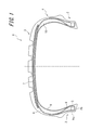
- FIG. 1 is a tire width direction sectional view showing a run flat tire according to an embodiment of the present invention.
- FIG. 2 is a cross-sectional view in the tire width direction showing an enlargement of the periphery of a bead portion of the run flat tire of FIG. 1.
- FIG. 1 is a cross-sectional view in the tire width direction showing a run-flat tire 1 (hereinafter also simply referred to as “tire”) according to an embodiment of the present invention in an unloaded state without being mounted on an applied rim.
- the run flat tire 1 adjusts the interval of each bead portion 2 to be described later to the interval when the bead portion 2 is attached to the applicable rim, and contacts the rim flange when each bead portion 2 is attached to the applicable rim.
- the bead back surface Po which becomes the outer surface of the portion 2 is in a state of being perpendicular to the tire width direction.
- the run-flat tire 1 shown in FIG. 1 is a so-called run-flat tire 1 that can travel a certain distance without losing the load supporting ability even when the tire internal pressure is reduced by puncture or the like. 3, a pair of sidewall portions 4 that are continuous on both sides of the tread portion 3, and a bead portion 2 that is continuous with each sidewall portion 4. Further, the run-flat tire 1 includes a carcass main body portion that extends in a toroidal manner between the bead cores 5 embedded in each bead portion 2 over the tread portion 3, the sidewall portion 4, and the bead portion 2, and the carcass main body portion.
- the carcass 6 is located on the outer side in the tire width direction and includes a carcass folding portion that extends from the carcass main body portion and is folded around the bead core 5 from the inner side in the tire radial direction toward the outer side in the tire radial direction. .
- FIG. 1 shows a case where the belt 7 is composed of a total of three belt layers, in the run-flat tire 1 of the present invention, the number of belt layers and the arrangement position thereof are arbitrary as required. The number of layers and the arrangement position can be set.
- the bead core 5 embedded in the bead portion 2 is sandwiched between the carcass main body portion and the carcass folding portion located on the outer side in the tire width direction of the carcass main body portion.
- a bead filler 8 having a substantially triangular cross section is disposed along the carcass 6 such that the thickness gradually decreases toward the outer side in the tire radial direction.
- the carcass 6 in the side wall portion 4 is arranged on the inner side in the tire width direction, specifically, on the carcass 6 in the region extending from the tire width direction end portion of the tread portion 3 to the bead portion 2 and on the tire inner surface side of the carcass 6.
- a side reinforcing rubber 10 having a substantially crescent-shaped cross section made of rubber having a relatively high elastic modulus is disposed between the inner liner 9 provided.
- the side reinforcing rubber 10 may be disposed outside the carcass 6, or may be disposed between the carcass layers when two carcass layers forming the carcass 6 are provided.
- the bead portion 2 is formed with curved outer contour lines of the bead heel 2h and the bead toe 2t in a cross-sectional view in the tire width direction. Further, the bead heel 2h of the bead portion 2 is located on the outer side in the tire radial direction than the bead toe 2t.
- the outer contour line of the bead heel 2h or the bead toe 2t can be formed to be square.
- the inventors conducted sincere research on the method of securing the resistance to rim detachment while maintaining the durability of the side reinforcing rubber of the run flat tire, and obtained the following knowledge. That is, the improvement of the rim resistance of the run-flat tire can be realized by increasing the tightening of the bead portion to the rim. On the other hand, if the tightening to the rim is increased, the bead part is excessively fixed to the rim, and when the lateral force is applied during run flat running, the movement of the bead part in the rim is suppressed.
- the diameter Dc of the inner end in the tire radial direction of the bead core 5 is 3.0 to larger than the rim diameter Dr of the applied rim in the tire width direction sectional view.
- the diameter Dh of the bead heel point Ih is 4.5 mm larger, and is 1.7 to 2.9 mm smaller than the rim diameter Dr.
- the bead core 2 is strongly fixed to the rim by increasing the diameter Dc of the bead core 5 within a range of 4.5 mm or less with respect to the rim diameter Dr of the applied rim, and the rim seat Since the contact pressure of the bead base surface Pb of the bead part 2 with respect to is improved, even if a lateral force is applied during the run-flat running, the positional deviation of the bead part 2 can be suppressed. Further, by setting the diameter Dc to be larger than the rim diameter Dr by 3.0 mm or more, even if a lateral force is applied during run-flat traveling, the bead portion 2 is not fixed to the rim excessively. Therefore, it is possible to prevent concentration of strain on the side reinforcement rubber 10 and therefore, the durability of the side reinforcing rubber 10 is not lowered.
- the bead heel 2h side portion of the bead portion 2 is strongly fixed to the rim, and the bead with respect to the rim seat is Since the contact pressure at the bead heel 2h side portion of the base surface Pb is improved, even if a lateral force is applied during the run-flat running, the positional deviation of the bead portion 2 can be sufficiently suppressed. As a result, sufficient rim detachment resistance can be ensured.
- the bead portion 2 is not excessively fixed to the rim.
- the concentration of strain on the reinforcing rubber 10 can be prevented, and therefore the durability of the side reinforcing rubber 10 is not lowered.
- the diameter Dc is a rim in a cross-sectional view in the tire width direction. More preferably, the diameter Dr is 3.0 to 4.2 mm larger than the diameter Dr, and the diameter Dh is 2.0 to 2.9 mm smaller than the rim diameter Dr.
- the section height is less than 120 mm, More preferably, the diameter Dc is 3.3 to 4.5 mm larger than the rim diameter Dr, and the diameter Dh is 1.7 to 2.6 mm smaller than the rim diameter Dr.
- “Section height” refers to a value obtained by multiplying “nominal width of tire cross section” by “nominal size of tire flatness”.
- the operation of mounting the run-flat tire on the rim is to place each bead part over the rim flange of the rim, once positioned in the well inside the rim hump, and then raised to a predetermined internal pressure of the tire. Then, the bead portion is carried over the rim hump so as to be positioned on the rim seat at a predetermined position.
- the rim flange or the rim hump over the bead portion when the rim is assembled is compared with a normal pneumatic tire. As a result, rim assembly tends to be difficult, and it is required that the rim assembly performance does not deteriorate.
- the outer contour line of the bead heel 2h of the bead portion 2 is formed from one arc in the tire width direction cross-sectional view, and the end E of the arc on the bead base surface Pb side.
- the bead core 5 is located on the inner side in the tire width direction than the position in the tire width direction at the outer end in the tire width direction. According to this, since the corner is eliminated by forming the outer contour line of the bead heel 2h from one arc, the rim assembly can be smoothly performed without being caught by the rim hump or the like.
- the rubber volume forming the bead heel 2h can be suppressed by positioning the end E of the arc on the inner side in the tire width direction than the outer end in the tire width direction of the bead core 5. As a result, the rim assembly property can be sufficiently maintained.
- the rubber flow of the bead portion 2 becomes smooth during vulcanization of the tire, and manufacturing defects can be reduced.
- the diameter Dc is 3.0 to 4.5 mm larger than the rim diameter Dr and the diameter Dh is larger than the rim diameter Dr in the tire width direction sectional view. Also, the rim assembly property can be maintained by reducing the diameter by 1.7 to 2.9 mm.
- the radius of curvature of the arc is preferably 5.0-8. 0 mm.
- the radius of curvature of the arc is preferably 5.0-8. 0 mm.
- the straight line connecting the bead heel point Ih and the bead toe point It has an angle ⁇ in the range of 12.2 to 14.7 ° with respect to the tire width direction. Just tilted. According to this, even if a lateral force is applied during run flat traveling, it is possible to improve the rim detachment resistance while preventing the concentration of strain on the side reinforcing rubber 10. That is, when the angle ⁇ is set to 12.2 ° or more, the contact pressure with respect to the rim of the bead toe 2t side portion of the bead portion 2 is increased. Can be sufficiently suppressed, and as a result, rim detachment resistance can be improved.
- the contact pressure on the bead toe 2t side portion does not become excessive, and therefore the bead portion 2 is not fixed to the rim, so that the distortion to the side reinforcing rubber 10 is reduced. Concentration can be prevented, and as a result, a decrease in durability of the side reinforcing rubber 10 can be effectively prevented.
- the angle ⁇ is 12. More preferably, it is in the range of 5 to 14.7 °, and when the section height is less than 120 mm, the angle ⁇ is in the range of 12.2 to 14.4 ° in a cross-sectional view in the tire width direction. More preferred.
- the outer contour of the bead base corresponding to the bead base surface Pb out of the outer contour of the bead portion 2 is a straight line in the tire width direction sectional view.
- a bead toe side portion 22 and a bead toe side portion 22 connected to the bead toe side portion 22 at a connecting point Ic are provided.
- the bead toe side portion 22 is 17.5 to Preferably, it is inclined by an angle ⁇ of 19.5 °.
- each inclination of the bead heel side part 21 and the bead toe side part 22 is different.
- a part of the curved portion 23 forming the outer contour line of the bead heel 2h is the bead heel side portion 21, and the end E of the curved portion 23 of the bead heel 2h (the outer contour of the bead heel 2h).
- the end E) of the line on the bead base surface Pb side is the connection point Ic
- the bead toe side portion 22 is inclined from the connection point Ic to the inside in the tire radial direction and before the curved portion 24 of the bead toe 2t.
- it protrudes toward the tire radial direction outer side at the connection point Ic.
- the bead toe point It is preferably located on the extension line of the bead toe side portion 22.
- the angle ⁇ is set to 17.5 ° or more, the contact pressure of the bead portion 2 with respect to the rim on the bead toe 2t side is increased, and even if a lateral force is applied during run flat running, the rim removal resistance is improved. It can be improved effectively.
- the angle ⁇ is not inclined too much, so that the rigidity of the bead toe 2t is increased, and when the tire 1 is mounted on the rim, for example, the bead portion 2 is When the rim flange is climbed over, the bead toe 2t smoothly climbs over the rim flange to reduce the amount of biting, so that damage such as chipping of the tip of the bead toe 2t does not occur (that is, the rim assembly property is maintained).
- the angle ⁇ to 19.5 ° or less the contact pressure of the bead toe side portion 22 with respect to the rim is made uniform and the friction coefficient is improved. Therefore, even if a lateral force is applied during run flat running, The detachability can be effectively improved.
- the angle ⁇ is 18.0 to 19 when the section height is 120 mm or more. More preferably, the angle ⁇ is 17.5 to 19.0 ° when the section height is less than 120 mm.
- a part of the curved portion 23 forming the outer contour line of the bead heel 2 h is a bead heel side portion 21, but the bead base surface on the inner side in the tire width direction than the curved portion 23.
- a bead heel side portion 21 and a connection point Ic can be provided on Pb separately from the curved portion 23 and its end E. In such a case, when the bead heel side portion 21 is linear, it is preferable that the inclination of the bead heel side portion 21 with respect to the tire width direction is less than 17.5 °.
- the connecting point Ic is preferably located within the range of the position of the bead core 5 in the tire width direction, in other words, the inside of the bead core 5 in the tire radial direction.
- the contact pressure with respect to the rim of the bead portion 2 changes on the bead heel 2h side and the bead toe 2t side with the connection point Ic as a boundary, but by positioning the connection point Ic on the inner side in the tire radial direction of the bead core 5 having high rigidity, The non-uniformity of the contact pressure can be reduced.
- the connecting point Ic is the end E of the curved portion 23 of the bead heel 2h.
- the connecting point Ic and the end E are different, the connecting point Ic from the same viewpoint. It is preferable that Ic and the end E are located inside the bead core 5 in the tire radial direction.
- the angle ⁇ of the bead toe point It is 30 ° or more. According to this, since the rigidity of the bead toe 2t is improved, for example, when the tire 1 is mounted on the rim, damage such as chipping of the bead toe 2t can be prevented.
- the angle ⁇ of the bead toe point It is in the range of 30 to 90 °.
- a textile chafer is disposed at least between the bead core 5 and the bead base surface Pb, although not shown.
- a reinforcing cord layer formed by covering a layer formed by arranging organic fiber cords with rubber can be used.
- the textile chafer one in which the cord is inclined at an angle of 30 to 60 °, preferably 45 ° with respect to the tire circumferential direction can be used.
- the tires of Examples 1 to 21 are run-flat tires of tire size 205 / 55R16 having side reinforcement rubber, and have the configurations shown in FIGS. 1 and 2 according to the specifications shown in Table 1.
- the tires of Comparative Examples 1 to 4 are the same as the tires of Example 1 except that each configuration of the bead portion is different depending on the specifications shown in Table 1. The performance of such a test tire was evaluated by the following method. The results are shown in Table 1.
- Rim assembly test When mounting each test tire on a rim having a rim size of 6.5J-16, whether or not the bead toe was damaged was visually observed and evaluated. In addition, it was evaluated whether or not the bead part can get over the rim hump with the standard pressure applied when each test tire is mounted on the rim (meaning that the bead part cannot get over the rim hump in one operation, In that case, it is necessary to release the pressure and reapply the lubricant to the bead portion or rim). When the bead toe is not damaged, and when the bead portion can get over the rim hump and the tire can be attached to the rim at a normal pressure, it means that the rim assembly is good.
- Run flat turning test Each test tire was mounted on a rim similar to that described above, its internal pressure was 0 kPa, and the tire was attached to a vehicle having a weight of 2 t. Next, after running the vehicle for 5 km at a speed of 20 km / h and running-in, the vehicle enters the turning circuit with a radius of 25 m at a predetermined speed, and stops when the turning circuit has made a 1/3 turn. It was. At this time, if the tire does not come off the rim even if the vehicle is driven twice on the turning circuit, or if the side reinforcing rubber of the tire is not damaged (that is, the vehicle can run), the speed is 1 km / h. I went up and made it run in the same way. Then, the speed (turning limit) when either the rim disengagement or the side reinforcing rubber was damaged was measured. The higher the speed is, the more the rim resistance is secured while maintaining the durability of the side reinforcing rubber for the tire.
- the tires of Examples 1 to 21 have a higher limit speed in the turning circuit in the run-flat turning test than the tires of Comparative Examples 1 to 4, that is, the durability of the side reinforcing rubber is maintained. However, it was found that sufficient rim detachment resistance can be secured even during run-flat driving. Note that the tire of Example 21 was not subjected to the run-flat turning test because the bead toe was damaged in the rim assembly test.
Landscapes
- Engineering & Computer Science (AREA)
- Mechanical Engineering (AREA)
- Tires In General (AREA)
Abstract
L'invention concerne un pneumatique à mobilité étendue lequel permet, tout en maintenant la durabilité du caoutchouc de renforcement latéral, d'assurer une résistance au détachement de la jante suffisante, même lorsque le véhicule roule après crevaison. Plus spécifiquement, ce pneumatique (1) à mobilité étendue comporte: une partie bande de roulement; une paire de parties de parois latérales contigües aux deux côtés de la partie bande de roulement; une partie talon (2) contigüe à chaque partie de paroi latérale; une tringle (5) de talon enfouie dans la partie talon (2); et un caoutchouc de renforcement dont la section transversale est en forme de croissant, et qui est situé sur les parties de parois latérales. Ce pneumatique (1) à mobilité étendue se caractérise en ce que, dans une vue en coupe du pneumatique dans le sens de la largeur, le diamètre (Dc) au niveau d'une extrémité interne en direction du diamètre du pneu de la tringle (5) de talon est supérieur de 3,0 à 4,5 mm au diamètre (Dr) de la jante, et en ce que le diamètre (Dh) d'un point (Ih) du talon de bourrelet de la partie talon (2) est inférieur de 1,7 à 2,9 mm au diamètre (Dr) de la jante de ce pneumatique.
Priority Applications (3)
| Application Number | Priority Date | Filing Date | Title |
|---|---|---|---|
| EP14800584.6A EP3000625B1 (fr) | 2013-05-20 | 2014-05-19 | Pneumatique à mobilité étendue |
| US14/787,542 US20160121662A1 (en) | 2013-05-20 | 2014-05-19 | Run flat tire |
| CN201480029404.1A CN105228837B (zh) | 2013-05-20 | 2014-05-19 | 缺气保用轮胎 |
Applications Claiming Priority (2)
| Application Number | Priority Date | Filing Date | Title |
|---|---|---|---|
| JP2013106407A JP5809191B2 (ja) | 2013-05-20 | 2013-05-20 | 乗用車用のランフラットタイヤ |
| JP2013-106407 | 2013-05-20 |
Publications (1)
| Publication Number | Publication Date |
|---|---|
| WO2014188700A1 true WO2014188700A1 (fr) | 2014-11-27 |
Family
ID=51933267
Family Applications (1)
| Application Number | Title | Priority Date | Filing Date |
|---|---|---|---|
| PCT/JP2014/002629 Ceased WO2014188700A1 (fr) | 2013-05-20 | 2014-05-19 | Pneumatique à mobilité étendue |
Country Status (5)
| Country | Link |
|---|---|
| US (1) | US20160121662A1 (fr) |
| EP (1) | EP3000625B1 (fr) |
| JP (1) | JP5809191B2 (fr) |
| CN (1) | CN105228837B (fr) |
| WO (1) | WO2014188700A1 (fr) |
Cited By (1)
| Publication number | Priority date | Publication date | Assignee | Title |
|---|---|---|---|---|
| US20210339577A1 (en) * | 2020-04-30 | 2021-11-04 | Toyo Tire Corporation | Pneumatic tire |
Families Citing this family (5)
| Publication number | Priority date | Publication date | Assignee | Title |
|---|---|---|---|---|
| JP5809192B2 (ja) * | 2013-05-20 | 2015-11-10 | 株式会社ブリヂストン | 乗用車用のランフラットタイヤ |
| JP6763188B2 (ja) * | 2016-04-18 | 2020-09-30 | 住友ゴム工業株式会社 | 空気入りタイヤ |
| CN106739843A (zh) * | 2017-01-20 | 2017-05-31 | 安徽佳通乘用子午线轮胎有限公司 | 适用于5°斜底轮辋的全钢载重无内轮胎 |
| JP7367488B2 (ja) * | 2019-11-26 | 2023-10-24 | 住友ゴム工業株式会社 | 空気入りタイヤ |
| CN118219710A (zh) * | 2024-04-22 | 2024-06-21 | 肇庆骏鸿实业有限公司 | 一种防异响的缺气保用轮胎 |
Citations (4)
| Publication number | Priority date | Publication date | Assignee | Title |
|---|---|---|---|---|
| JP2001225614A (ja) * | 2000-02-15 | 2001-08-21 | Yokohama Rubber Co Ltd:The | 空気入りタイヤ |
| JP2002513361A (ja) * | 1997-06-10 | 2002-05-08 | ミシュラン ルシェルシュ エ テクニク ソシエテ アノニム | ビード/リム境界部を改良したランフラットタイヤ |
| JP2009126262A (ja) | 2007-11-21 | 2009-06-11 | Bridgestone Corp | ランフラットタイヤ |
| JP2010111173A (ja) * | 2008-11-04 | 2010-05-20 | Sumitomo Rubber Ind Ltd | ランフラットタイヤ |
Family Cites Families (10)
| Publication number | Priority date | Publication date | Assignee | Title |
|---|---|---|---|---|
| GB1436725A (en) * | 1972-06-21 | 1976-05-26 | Bridgestone Tire Co Ltd | Pneumatic safety tyre |
| IN155019B (fr) * | 1979-12-06 | 1984-12-22 | Dunlop Ltd | |
| US5217549A (en) * | 1991-04-04 | 1993-06-08 | Bridgestone/Firestone, Inc. | Pneumatic safety tire |
| CA2089450A1 (fr) * | 1992-02-21 | 1993-08-22 | Masanao Yoshida | Pneumatique |
| JP2733730B2 (ja) * | 1992-12-28 | 1998-03-30 | 住友ゴム工業株式会社 | 空気入りタイヤ |
| JPH0920110A (ja) * | 1995-07-04 | 1997-01-21 | Bridgestone Corp | 空気入りラジアル・タイヤ |
| JP3485413B2 (ja) * | 1996-03-29 | 2004-01-13 | 住友ゴム工業株式会社 | 空気入りタイヤのビード部構造 |
| JPH1191321A (ja) * | 1997-09-25 | 1999-04-06 | Bridgestone Corp | 重荷重用空気入りタイヤ |
| JP5809192B2 (ja) * | 2013-05-20 | 2015-11-10 | 株式会社ブリヂストン | 乗用車用のランフラットタイヤ |
| JP6317130B2 (ja) * | 2014-02-20 | 2018-04-25 | 株式会社ブリヂストン | ランフラットタイヤ |
-
2013
- 2013-05-20 JP JP2013106407A patent/JP5809191B2/ja not_active Expired - Fee Related
-
2014
- 2014-05-19 US US14/787,542 patent/US20160121662A1/en not_active Abandoned
- 2014-05-19 WO PCT/JP2014/002629 patent/WO2014188700A1/fr not_active Ceased
- 2014-05-19 EP EP14800584.6A patent/EP3000625B1/fr not_active Not-in-force
- 2014-05-19 CN CN201480029404.1A patent/CN105228837B/zh not_active Expired - Fee Related
Patent Citations (4)
| Publication number | Priority date | Publication date | Assignee | Title |
|---|---|---|---|---|
| JP2002513361A (ja) * | 1997-06-10 | 2002-05-08 | ミシュラン ルシェルシュ エ テクニク ソシエテ アノニム | ビード/リム境界部を改良したランフラットタイヤ |
| JP2001225614A (ja) * | 2000-02-15 | 2001-08-21 | Yokohama Rubber Co Ltd:The | 空気入りタイヤ |
| JP2009126262A (ja) | 2007-11-21 | 2009-06-11 | Bridgestone Corp | ランフラットタイヤ |
| JP2010111173A (ja) * | 2008-11-04 | 2010-05-20 | Sumitomo Rubber Ind Ltd | ランフラットタイヤ |
Cited By (1)
| Publication number | Priority date | Publication date | Assignee | Title |
|---|---|---|---|---|
| US20210339577A1 (en) * | 2020-04-30 | 2021-11-04 | Toyo Tire Corporation | Pneumatic tire |
Also Published As
| Publication number | Publication date |
|---|---|
| JP2014226977A (ja) | 2014-12-08 |
| EP3000625B1 (fr) | 2018-01-03 |
| CN105228837A (zh) | 2016-01-06 |
| EP3000625A1 (fr) | 2016-03-30 |
| JP5809191B2 (ja) | 2015-11-10 |
| EP3000625A4 (fr) | 2016-06-01 |
| CN105228837B (zh) | 2017-07-04 |
| US20160121662A1 (en) | 2016-05-05 |
Similar Documents
| Publication | Publication Date | Title |
|---|---|---|
| CN101903196B (zh) | 充气轮胎 | |
| CN109562645B (zh) | 泄气保用轮胎 | |
| JP5091223B2 (ja) | 空気入りラジアルタイヤ | |
| JP5809191B2 (ja) | 乗用車用のランフラットタイヤ | |
| EP2949483B1 (fr) | Pneumatique | |
| CN101541566A (zh) | 充气轮胎 | |
| CN106029405B (zh) | 缺气保用轮胎 | |
| JP5809192B2 (ja) | 乗用車用のランフラットタイヤ | |
| CN104070931B (zh) | 充气轮胎 | |
| CN103906631A (zh) | 重载用充气子午线轮胎 | |
| WO2012066766A1 (fr) | Pneumatique | |
| CN111372792B (zh) | 充气轮胎 | |
| JP2007099003A (ja) | 空気入りラジアルタイヤ | |
| JP2002240516A (ja) | 空気入りタイヤ | |
| JP4436514B2 (ja) | ビード部耐久性に優れる空気入りタイヤ | |
| JP2004276763A (ja) | 空気入りタイヤ | |
| JP2006264492A (ja) | 空気入りランフラットタイヤ | |
| JP4978087B2 (ja) | 空気入りタイヤ | |
| JP5235640B2 (ja) | 空気入りタイヤ | |
| JP2009262865A (ja) | 空気入りタイヤ | |
| JP7611687B2 (ja) | 空気入りタイヤ | |
| JP5749995B2 (ja) | オフロード用の空気入りタイヤ | |
| JP5470216B2 (ja) | 空気入りタイヤ | |
| JP2006111219A (ja) | 空気入りタイヤ | |
| JP2006159985A (ja) | 空気入りランフラットタイヤ |
Legal Events
| Date | Code | Title | Description |
|---|---|---|---|
| WWE | Wipo information: entry into national phase |
Ref document number: 201480029404.1 Country of ref document: CN |
|
| 121 | Ep: the epo has been informed by wipo that ep was designated in this application |
Ref document number: 14800584 Country of ref document: EP Kind code of ref document: A1 |
|
| WWE | Wipo information: entry into national phase |
Ref document number: 14787542 Country of ref document: US |
|
| WWE | Wipo information: entry into national phase |
Ref document number: 2014800584 Country of ref document: EP |
|
| NENP | Non-entry into the national phase |
Ref country code: DE |