WO2014188961A1 - タービン翼の冷却構造 - Google Patents
タービン翼の冷却構造 Download PDFInfo
- Publication number
- WO2014188961A1 WO2014188961A1 PCT/JP2014/062992 JP2014062992W WO2014188961A1 WO 2014188961 A1 WO2014188961 A1 WO 2014188961A1 JP 2014062992 W JP2014062992 W JP 2014062992W WO 2014188961 A1 WO2014188961 A1 WO 2014188961A1
- Authority
- WO
- WIPO (PCT)
- Prior art keywords
- cooling medium
- cooling
- passage
- turbine blade
- cylindrical spaces
- Prior art date
- Legal status (The legal status is an assumption and is not a legal conclusion. Google has not performed a legal analysis and makes no representation as to the accuracy of the status listed.)
- Ceased
Links
Images


Classifications
-
- F—MECHANICAL ENGINEERING; LIGHTING; HEATING; WEAPONS; BLASTING
- F01—MACHINES OR ENGINES IN GENERAL; ENGINE PLANTS IN GENERAL; STEAM ENGINES
- F01D—NON-POSITIVE DISPLACEMENT MACHINES OR ENGINES, e.g. STEAM TURBINES
- F01D5/00—Blades; Blade-carrying members; Heating, heat-insulating, cooling or antivibration means on the blades or the members
- F01D5/12—Blades
- F01D5/14—Form or construction
- F01D5/18—Hollow blades, i.e. blades with cooling or heating channels or cavities; Heating, heat-insulating or cooling means on blades
- F01D5/187—Convection cooling
-
- F—MECHANICAL ENGINEERING; LIGHTING; HEATING; WEAPONS; BLASTING
- F05—INDEXING SCHEMES RELATING TO ENGINES OR PUMPS IN VARIOUS SUBCLASSES OF CLASSES F01-F04
- F05D—INDEXING SCHEME FOR ASPECTS RELATING TO NON-POSITIVE-DISPLACEMENT MACHINES OR ENGINES, GAS-TURBINES OR JET-PROPULSION PLANTS
- F05D2240/00—Components
- F05D2240/20—Rotors
- F05D2240/30—Characteristics of rotor blades, i.e. of any element transforming dynamic fluid energy to or from rotational energy and being attached to a rotor
- F05D2240/303—Characteristics of rotor blades, i.e. of any element transforming dynamic fluid energy to or from rotational energy and being attached to a rotor related to the leading edge of a rotor blade
-
- F—MECHANICAL ENGINEERING; LIGHTING; HEATING; WEAPONS; BLASTING
- F05—INDEXING SCHEMES RELATING TO ENGINES OR PUMPS IN VARIOUS SUBCLASSES OF CLASSES F01-F04
- F05D—INDEXING SCHEME FOR ASPECTS RELATING TO NON-POSITIVE-DISPLACEMENT MACHINES OR ENGINES, GAS-TURBINES OR JET-PROPULSION PLANTS
- F05D2250/00—Geometry
- F05D2250/10—Two-dimensional
- F05D2250/14—Two-dimensional elliptical
- F05D2250/141—Two-dimensional elliptical circular
-
- F—MECHANICAL ENGINEERING; LIGHTING; HEATING; WEAPONS; BLASTING
- F05—INDEXING SCHEMES RELATING TO ENGINES OR PUMPS IN VARIOUS SUBCLASSES OF CLASSES F01-F04
- F05D—INDEXING SCHEME FOR ASPECTS RELATING TO NON-POSITIVE-DISPLACEMENT MACHINES OR ENGINES, GAS-TURBINES OR JET-PROPULSION PLANTS
- F05D2250/00—Geometry
- F05D2250/10—Two-dimensional
- F05D2250/15—Two-dimensional spiral
-
- F—MECHANICAL ENGINEERING; LIGHTING; HEATING; WEAPONS; BLASTING
- F05—INDEXING SCHEMES RELATING TO ENGINES OR PUMPS IN VARIOUS SUBCLASSES OF CLASSES F01-F04
- F05D—INDEXING SCHEME FOR ASPECTS RELATING TO NON-POSITIVE-DISPLACEMENT MACHINES OR ENGINES, GAS-TURBINES OR JET-PROPULSION PLANTS
- F05D2250/00—Geometry
- F05D2250/20—Three-dimensional
- F05D2250/23—Three-dimensional prismatic
- F05D2250/231—Three-dimensional prismatic cylindrical
-
- F—MECHANICAL ENGINEERING; LIGHTING; HEATING; WEAPONS; BLASTING
- F05—INDEXING SCHEMES RELATING TO ENGINES OR PUMPS IN VARIOUS SUBCLASSES OF CLASSES F01-F04
- F05D—INDEXING SCHEME FOR ASPECTS RELATING TO NON-POSITIVE-DISPLACEMENT MACHINES OR ENGINES, GAS-TURBINES OR JET-PROPULSION PLANTS
- F05D2250/00—Geometry
- F05D2250/20—Three-dimensional
- F05D2250/25—Three-dimensional helical
-
- F—MECHANICAL ENGINEERING; LIGHTING; HEATING; WEAPONS; BLASTING
- F05—INDEXING SCHEMES RELATING TO ENGINES OR PUMPS IN VARIOUS SUBCLASSES OF CLASSES F01-F04
- F05D—INDEXING SCHEME FOR ASPECTS RELATING TO NON-POSITIVE-DISPLACEMENT MACHINES OR ENGINES, GAS-TURBINES OR JET-PROPULSION PLANTS
- F05D2250/00—Geometry
- F05D2250/30—Arrangement of components
- F05D2250/31—Arrangement of components according to the direction of their main axis or their axis of rotation
- F05D2250/312—Arrangement of components according to the direction of their main axis or their axis of rotation the axes being parallel to each other
-
- F—MECHANICAL ENGINEERING; LIGHTING; HEATING; WEAPONS; BLASTING
- F05—INDEXING SCHEMES RELATING TO ENGINES OR PUMPS IN VARIOUS SUBCLASSES OF CLASSES F01-F04
- F05D—INDEXING SCHEME FOR ASPECTS RELATING TO NON-POSITIVE-DISPLACEMENT MACHINES OR ENGINES, GAS-TURBINES OR JET-PROPULSION PLANTS
- F05D2250/00—Geometry
- F05D2250/30—Arrangement of components
- F05D2250/31—Arrangement of components according to the direction of their main axis or their axis of rotation
- F05D2250/314—Arrangement of components according to the direction of their main axis or their axis of rotation the axes being inclined in relation to each other
-
- F—MECHANICAL ENGINEERING; LIGHTING; HEATING; WEAPONS; BLASTING
- F05—INDEXING SCHEMES RELATING TO ENGINES OR PUMPS IN VARIOUS SUBCLASSES OF CLASSES F01-F04
- F05D—INDEXING SCHEME FOR ASPECTS RELATING TO NON-POSITIVE-DISPLACEMENT MACHINES OR ENGINES, GAS-TURBINES OR JET-PROPULSION PLANTS
- F05D2250/00—Geometry
- F05D2250/70—Shape
- F05D2250/72—Shape symmetric
-
- F—MECHANICAL ENGINEERING; LIGHTING; HEATING; WEAPONS; BLASTING
- F05—INDEXING SCHEMES RELATING TO ENGINES OR PUMPS IN VARIOUS SUBCLASSES OF CLASSES F01-F04
- F05D—INDEXING SCHEME FOR ASPECTS RELATING TO NON-POSITIVE-DISPLACEMENT MACHINES OR ENGINES, GAS-TURBINES OR JET-PROPULSION PLANTS
- F05D2260/00—Function
- F05D2260/20—Heat transfer, e.g. cooling
- F05D2260/201—Heat transfer, e.g. cooling by impingement of a fluid
-
- F—MECHANICAL ENGINEERING; LIGHTING; HEATING; WEAPONS; BLASTING
- F05—INDEXING SCHEMES RELATING TO ENGINES OR PUMPS IN VARIOUS SUBCLASSES OF CLASSES F01-F04
- F05D—INDEXING SCHEME FOR ASPECTS RELATING TO NON-POSITIVE-DISPLACEMENT MACHINES OR ENGINES, GAS-TURBINES OR JET-PROPULSION PLANTS
- F05D2260/00—Function
- F05D2260/20—Heat transfer, e.g. cooling
- F05D2260/221—Improvement of heat transfer
- F05D2260/2212—Improvement of heat transfer by creating turbulence
-
- F—MECHANICAL ENGINEERING; LIGHTING; HEATING; WEAPONS; BLASTING
- F05—INDEXING SCHEMES RELATING TO ENGINES OR PUMPS IN VARIOUS SUBCLASSES OF CLASSES F01-F04
- F05D—INDEXING SCHEME FOR ASPECTS RELATING TO NON-POSITIVE-DISPLACEMENT MACHINES OR ENGINES, GAS-TURBINES OR JET-PROPULSION PLANTS
- F05D2260/00—Function
- F05D2260/20—Heat transfer, e.g. cooling
- F05D2260/221—Improvement of heat transfer
- F05D2260/2214—Improvement of heat transfer by increasing the heat transfer surface
Definitions
- the present invention relates to a structure for cooling a turbine blade in a turbine of a gas turbine engine from the inside.
- the turbine constituting the gas turbine engine is disposed downstream of the combustor and is supplied with high-temperature gas combusted in the combustor, so that it is exposed to high temperatures during operation of the gas turbine engine. Therefore, it is necessary to cool the turbine blades, that is, the stationary blades and the moving blades of the turbine.
- As a structure for cooling such turbine blades it is known that a part of air compressed by a compressor is introduced into a cooling passage formed in the blades, and the turbine blades are cooled by using compressed air as a cooling medium. Yes.
- a cooling structure it has been proposed to form a cooling passage by a circular pipe in a turbine blade and supply a cooling air from one end thereof to generate a swirling flow (for example, Patent Document 1). reference).
- an object of the present invention is to provide a cooling system capable of cooling the turbine blades with high efficiency by making the temperature distribution of the cooling medium passing through the cooling passages in the turbine blades uniform in order to solve the above-described problems. To provide a structure.
- a turbine blade cooling structure is a structure for cooling a turbine blade from the inside, and cooling medium passages provided in the turbine blade extend in parallel to each other.
- a part of the plurality of substantially cylindrical spaces has a shape overlapping each other, and the cooling medium supply passage for supplying the cooling medium to the cooling medium passage includes the cooling medium in a portion including a peripheral wall of the cooling medium passage. They are connected in a direction that forms an acute angle with the longitudinal direction of the medium passage.
- the cooling medium supplied to the cooling medium passage from the portion including the peripheral wall of the cooling medium passage flows into the plurality of cylindrical spaces, and forms a swirling flow in each cylindrical space. Further, a part of each swirl flow in both cylindrical spaces flows into the other cylindrical space through the overlapping region of both spaces.
- the mixing of the cooling medium is promoted, and the temperature distribution in the cooling medium is made uniform. High cooling efficiency can be obtained. Furthermore, when each swirl flow flows into the other cylindrical space, it collides with the partition sides formed between the cylindrical spaces, thereby providing a high cooling effect due to the impingement effect.
- the overlapping length W along a straight line connecting the centers of the two cross-sectional circles of the two adjacent cylindrical spaces is the cross-sectional diameter D1 of one cylindrical space and the other cylindrical space. It is preferable that the two adjacent cylindrical spaces overlap with each other so that 0.05 ⁇ W / ((D1 + D2) / 2) ⁇ 0.35 is satisfied.
- a cooling medium supply passage for supplying a cooling medium to the cooling medium passage may be connected to an overlapping region of two cylindrical spaces adjacent to the cooling medium passage.
- the cooling medium supply passage is connected to the overlapping region so that the cooling medium supplied from the cooling medium supply passage collides with a partition side formed between the two adjacent cylindrical spaces. It is preferable.
- the cooling medium supplied from the cooling medium supply passage collides with the partition side formed between the two spaces, so that the cooling medium is distributed almost evenly in the two cylindrical spaces. Since a swirling flow in the opposite direction with high directivity is formed along the inner wall surface forming the cooling medium, mixing of the cooling medium is further promoted. Also, in the cooling medium supply portion, the cooling medium is collided with the partition side, whereby the cooling of the wall surface is promoted by the impingement effect. Due to these effects, extremely high cooling efficiency can be obtained.
- the cooling medium supply passage for supplying the cooling medium passage to the cooling medium passage is a straight line connecting between the centers of both cross-sectional circles of two cylindrical spaces adjacent to each other in the cooling medium passage. You may connect to the side part on the opposite side to the overlapping area
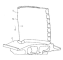
- FIG. 1 is a perspective view showing a moving blade 1 which is a turbine blade of a turbine of a gas turbine engine to which a turbine blade cooling structure according to a first embodiment of the present invention is applied.
- the turbine rotor blade 1 has a platform 2 connected to the outer peripheral portion of the turbine disk, so that a large number of turbine blades 1 are implanted in the circumferential direction to form a turbine.
- the turbine rotor blade 1 is exposed to the hot gas G flowing in the direction of the arrow supplied from the combustor.
- the upstream side left side in FIG.
- the cooling structure is applied to the inside of the front end portion 1 a that is particularly high in the turbine rotor blade 1.
- a first coolant passage 5 extending along the radial direction of the turbine (the vertical direction in the figure) is formed in the front end 1a of the turbine rotor blade 1.
- Compressed air from the compressor used as the cooling medium CL is introduced into the turbine rotor blade 1 through a cooling medium introduction passage 6 formed in the turbine disk 3.
- a part of the cooling medium CL introduced into the turbine rotor blade 1 is supplied to the first cooling medium passage 5.
- the remaining part of the cooling medium CL introduced into the turbine rotor blade 1 is supplied to the second cooling medium passage 7 for cooling the rear portion 1b of the turbine rotor blade 1.
- the cooling medium CL supplied to the first cooling medium passage 5 is discharged from the discharge hole 8 communicating with the outside of the turbine rotor blade 1.
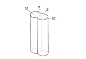
- the first cooling medium passage 5 has a shape in which a plurality of (two in this example) substantially cylindrical cylindrical spaces S1 and S2 extending in parallel with each other overlap each other. Yes. That is, as shown in FIG. 4, the cross section of the first cooling medium passage 5 has a shape in which two circles (hereinafter referred to as cross-sectional circles) C1 and C2 are partially overlapped.
- substantially cylindrical means a cylindrical shape having a circular cross-sectional shape, or a cylindrical shape having an elliptical shape in which the ratio of the short axis length to the long axis length is 0.5 or more. means.
- the diameter D1 of one cross-sectional circle C1 and the diameter D2 of the other cross-sectional circle C2 are set to the same value, but both the diameters D1, D2 may be set to different values.
- the degree of overlap between the two adjacent cylindrical spaces S1 and S2 is closer to each other than the circumscribed state of the cross-sectional circles C1 and C2, and the inscribed state (when both diameters D1 and D2 are equal).
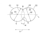
- the cross section circles C1 and C2 are not particularly limited as long as they are separated from each other. However, as a preferable overlapping degree for separating the cooling medium CL more effectively in the first cooling medium passage 5, the centers O1, O2 of the cross-sectional circles C1, C2 of the two adjacent cylindrical spaces S1, S2 are used.
- a direction along a straight line L connecting the centers O1 and O2 of both cross-sectional circles C1 and C2 of two adjacent cylindrical spaces S1 and S2 is simply referred to as a width direction X.
- the cooling medium supply passage 9 that supplies the cooling medium CL to the first cooling medium passage 5 is connected to the overlapping region M of the two adjacent cylindrical spaces S ⁇ b> 1 and S ⁇ b> 2 of the first cooling medium passage 5.
- the cooling medium supply is performed so that the cooling medium CL supplied from the cooling medium supply path 9 to the first cooling medium path 5 collides with the partition side 11 formed between two adjacent cylindrical spaces S1 and S2.
- the passage 9 is preferably connected to the overlap region M. More specifically, the cooling medium supply passage 9 is perpendicular to the width direction X in a cross-sectional view with respect to the overlapping region M between the cylindrical spaces S1 and S2, and the center of the passage is substantially at the opposing partition side 11. Connected in a matching arrangement.
- the partition side 11 partitions between the adjacent cylindrical space S1, S2, that is, the peripheral wall forming the cylindrical space S1 and the peripheral wall forming the cylindrical space S2. It is a side formed in a portion that extends in the longitudinal direction of the first cooling medium passage 5.
- the width direction X substantially matches the thickness direction of the turbine rotor blade 1, for example.
- the cooling medium CL supplied into the first cooling medium flow path 5 is sprayed to the outside from a plurality of injection holes 13 formed in the front end portion 1a, and the blade surface of the front end portion 1a is film-cooled.
- the cooling medium supply passage 9 is connected to a portion including the peripheral wall 15 of the first cooling medium passage 5 in a direction that forms an acute angle with respect to the longitudinal direction of the first cooling medium passage 5. Yes.
- the cooling medium supply passage 9 is connected to a corner portion 19 formed between the peripheral wall 15 and the bottom wall 17 at the upstream end portion of the first cooling medium passage 5.
- the angle ⁇ formed by the longitudinal direction of the cooling medium supply passage 9 and the first cooling medium passage 5 is not particularly limited as long as it is a value larger than 0 ° and smaller than 90 °, but the cooling medium CL is surely the first cooling medium.
- the angle ⁇ is preferably in the range of 15 ° ⁇ ⁇ 60 °, and more preferably in the range of 30 ° ⁇ ⁇ ⁇ 45 °.
- the first cooling medium passage 5 is connected to the first cooling medium passage 5 via the cooling medium supply passage 9 as shown in FIG.
- the swirl flows R1 and R2 are formed in the cylindrical spaces S1 and S2, respectively.
- a part of the swirl flow R1 flowing on the outer diameter side via the overlapping region M of the spaces S1, S2 is a cylinder.
- a part flowing from the shape space S1 to S2 and flowing on the outer diameter side of the swirl flow R2 flows from the cylindrical space S2 to S1.
- the cooling medium supply passage 9 is connected to the overlapping region M of the adjacent cylindrical spaces S1 and S2, the cooling medium CL is transferred from the cooling medium supply passage 9 to the first cooling medium passage 5. Even when it flows in, it collides with the partition side 11 formed between the two spaces S1, S2. By this partition side 11, the cooling medium CL is distributed almost evenly in the two cylindrical spaces S1, S2, and swirl flows R1, swirling in opposite directions along the inner wall surfaces forming the cylindrical spaces S1, S2, respectively. Since R2 is formed, mixing in the overlapping region M is further promoted. In the supply portion of the cooling medium CL, the cooling of the wall surface is promoted by the impingement effect by causing the cooling medium CL to collide with the partition side 11. Due to these effects, extremely high cooling efficiency can be obtained.
- the form of the cooling structure is not limited to the example described above, and the cooling medium passage provided in the turbine blade has a shape in which a plurality of substantially cylindrical spaces extending in parallel with each other overlap each other. And the cooling medium supply passage is connected to the portion including the peripheral wall of the cooling medium passage in a direction that forms an acute angle with respect to the longitudinal direction of the cooling medium passage, Mixing of the cooling medium CL is promoted when they flow into each other, and the effect that the temperature distribution in the cooling medium CL is made uniform is obtained.
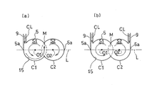
- the coolant supply passage 9 is opposite to the overlapping region M of the cylindrical space on the straight line L of the first coolant passage 5 as shown in FIG. It may be connected to one of the side portions 5a and 5a.
- two cooling medium supply passages 9 may be provided and connected to both sides of the first cooling medium passage 5.
- the cooling medium supply passage 9 is thus connected to the side portion 5a of the cooling medium passage 5
- the supply direction of the cooling medium CL by the cooling medium supply passage 9 in the cross-sectional view of the first cooling medium passage 5 is the cross-sectional circle C1.
- C2 is preferably set so as to be in the tangential direction.
- the configuration other than that specifically described above is such that the cooling medium supply passage 9 is in a portion including the peripheral wall 15 of the first cooling medium passage 5 with respect to the longitudinal direction of the first cooling medium passage 5.
- the configuration is the same as that of the first embodiment including the configuration connected in the direction that forms an acute angle.
- the number of cylindrical spaces forming the first cooling medium passage 5 is not limited to two, and for example, as shown in FIG. 9, three cylindrical spaces S1, S2, S3 May be arranged in this order, and adjacent cylindrical spaces S1 and S2, and S2 and S3 may have shapes that overlap each other.
- the shape of the first cooling medium passage 5 is formed by arranging three cylindrical spaces S1 to S3 in a substantially straight line (that is, each of the sectional circles C1, C2, and C3).
- the centers O1, O2, and O3 may be in the same straight line shape.
- the shape of the turbine blade portion to which this cooling structure is applied as shown in FIG.
- the width direction X1 of S2 and the width direction X2 of the cylindrical spaces S2, S3 may not be parallel (that is, the centers O1, O2, O3 of the cross-sectional circles C1, C2, C3 are not collinear). .
- the configuration other than that specifically described above is such that the cooling medium supply passage 9 is in a portion including the peripheral wall 15 of the first cooling medium passage 5 with respect to the longitudinal direction of the first cooling medium passage 5.
- the configuration is the same as that of the first embodiment including the configuration connected in the direction that forms an acute angle.
- the cooling structure exemplified as the first to third embodiments is applied not only to the front end portion 1a of the turbine rotor blade 1, but also to the second cooling medium passage 7 of the rear portion 1b instead of or in addition to this. Also good.
- the cooling medium CL is not limited to the compressed air from the compressor, and other gases or liquids generally used as a cooling medium may be used.
- the cooling structure according to the present invention can be applied to a turbine stationary blade in addition to the turbine rotor blade 1 as a turbine blade of a gas turbine.
- Turbine blade (turbine blade) 5 First cooling medium passage (cooling medium passage) 9 Cooling medium supply passage 15 Perimeter wall CL of cooling medium passage Cooling medium C1, C2, C3 Cross-sectional circle M Overlapping region O1, O2, O3 Center of cross-sectional circle S1, S2, S3 Cylindrical space
Landscapes
- Engineering & Computer Science (AREA)
- Mechanical Engineering (AREA)
- General Engineering & Computer Science (AREA)
- Turbine Rotor Nozzle Sealing (AREA)
Abstract
タービン翼(1)を内部から冷却するための構造において、前記タービン翼(1)内に冷却媒体通路(5)を設け、この冷却媒体通路(5)を、互いに平行に延びる複数のほぼ円筒状の空間(S1,S2)の一部が互いに重なり合った形状を有するものとし、前記冷却媒体通路に冷却媒体(CL)を供給する冷却媒体供給通路(9)を、前記冷却媒体通路の周壁(15)を含む部分に、前記冷却媒体通路の長手方向に対して鋭角をなす方向に接続する。
Description
本出願は、2013年5月20日出願の特願2013-105818の優先権を主張するものであり、その全体を参照により本願の一部をなすものとして引用する。
本発明は、ガスタービンエンジンのタービンにおけるタービン翼を、内部から冷却するための構造に関する。
ガスタービンエンジンを構成するタービンは、燃焼器の下流に配置され、燃焼器で燃焼された高温のガスが供給されるため、ガスタービンエンジンの運転中は高温にさらされる。したがって、タービン翼、すなわちタービンの静翼および動翼を冷却する必要がある。このようなタービン翼を冷却する構造として、圧縮機で圧縮された空気の一部を、翼内に形成した冷却通路に導入し、圧縮空気を冷却媒体としてタービン翼を冷却することが知られている。このような冷却構造の例として、タービン翼内に円管によって冷却通路を形成し、その一端から冷却用の空気を供給して旋回流を生じさせることが提案されている(例えば、特許文献1参照)。
圧縮空気の一部をタービン翼の冷却に用いる場合、外部から冷却媒体を導入する必要がなく、冷却構造を簡単にできるメリットがある一方、圧縮機で圧縮された空気を多量に冷却に用いるとエンジン効率の低下につながるので、最小限の空気量で効率的に冷却を行う必要がある。しかし、上記のように単純な円筒状の空間に空気を流すのみでは、冷却通路内で冷却媒体である空気が一方向に旋回するのみで、冷却媒体中の温度分布が不均一となり、十分な冷却効果は得られない。
そこで、本発明の目的は、上記の課題を解決すべく、タービン翼内の冷却通路を通過する冷却媒体の温度分布の均一化を図ることにより、高効率にタービン翼を冷却することができる冷却構造を提供することにある。
上記目的を達成するために、本発明に係るタービン翼の冷却構造は、タービン翼を内部から冷却するための構造であって、前記タービン翼内に設けられた冷却媒体通路が、互いに平行に延びる複数のほぼ円筒状の空間の一部が互いに重なり合った形状を有しており、前記冷却媒体通路に冷却媒体を供給する冷却媒体供給通路が、前記冷却媒体通路の周壁を含む部分に、前記冷却媒体通路の長手方向に対して鋭角をなす方向に接続されている。
この構成によれば、冷却媒体通路の周壁を含む部分から冷却媒体通路に供給された冷却媒体が、複数の円筒形状空間に分かれて流入し、各円筒形状空間内でそれぞれ旋回流を形成する。さらに、両空間の重なり領域を介して、両円筒形状空間内の各旋回流の一部が、他方の円筒形状空間へ流入する。このように、隣り合う円筒形状空間内で形成された冷却媒体の各旋回流が、他方へ流入し合う際に、冷却媒体の混合が促進され、冷却媒体内の温度分布が均一化されるので、高い冷却効率を得ることができる。さらには、各旋回流が他方の円筒形状空間に流入する際に、円筒形状空間の間に形成される区画辺に衝突することにより、インピンジ効果による高い冷却効果がもたらされる。
本発明の一実施形態において、隣り合う2つの前記円筒形状空間の両断面円の中心間を結ぶ直線に沿った重なり長さWが、一方の円筒形状空間の断面直径D1および他方の円筒形状空間の断面直径D2に対して、0.05≦W/((D1+D2)/2)≦0.35となるように前記隣り合う2つの円筒形状空間が重なっていることが好ましい。両円筒形状空間の重なり度合いをこのように設定することにより、両円筒形状空間内にそれぞれ分離した旋回流が生じ、かつ互いの旋回流が隣り合う円筒形状空間内に流入し合う現象を確実に発生させることができる。
本発明の一実施形態において、前記冷却媒体通路に冷却媒体を供給する冷却媒体供給通路が、前記冷却媒体通路の隣り合う2つの前記円筒形状空間の重なり領域に接続されていてもよい。その場合、前記冷却媒体供給通路から供給された冷却媒体が、前記隣り合う2つの円筒形状空間の間に形成される区画辺に衝突するように、前記冷却媒体供給通路が前記重なり領域に接続されていることが好ましい。この構成によれば、冷却媒体供給通路から供給された冷却媒体が、両空間の間に形成される区画辺に衝突することによって、両円筒形状空間内にほぼ均等に振り分けられ、各円筒形状空間を形成する内壁面に沿って指向性の高い逆方向の旋回流が形成されるので、冷却媒体の混合が一層促進される。また、冷却媒体の供給部分においても、冷却媒体を区画辺に衝突させることにより、インピンジ効果によって壁面の冷却が促進される。これらの効果により、極めて高い冷却効率を得ることができる。
本発明の一実施形態において、前記冷却媒体通路に冷却媒体を供給する冷却媒体供給通路が、前記冷却媒体通路の隣り合う2つの前記円筒形状空間の両断面円の中心間を結ぶ直線上の前記円筒形状空間の重なり領域と反対側の側部に接続されていてもよい。この構成によれば、当該冷却構造を適用するタービン翼の部位の形状に応じた柔軟な設計が可能となる。
請求の範囲および/または明細書および/または図面に開示された少なくとも2つの構成のどのような組合せも、本発明に含まれる。特に、請求の範囲の各請求項の2つ以上のどのような組合せも、本発明に含まれる。
この発明は、添付の図面を参考にした以下の好適な実施形態の説明から、より明瞭に理解されるであろう。しかしながら、実施形態および図面は単なる図示および説明のためのものであり、この発明の範囲を定めるために利用されるべきものではない。この発明の範囲は添付の請求の範囲によって定まる。添付図面において、複数の図面における同一の符号は、同一または相当する部分を示す。
本発明の第1実施形態に係る冷却構造が適用されるタービン翼の一例を示す斜視図である。
図1のタービン翼の冷却構造を模式的に示す断面図である。
図2の冷却構造の冷却媒体通路の形状を示す斜視図である。
図2の冷却構造の冷却媒体通路の形状を示す断面図である。
図2のタービン翼の前端部の横断面図である。
図2の冷却構造の作用を模式的に示す断面図である。
図2の冷却構造の冷却媒体供給通路を模式的に示す断面図である。
本発明の第2実施形態に係るタービン翼の冷却構造の例を模式的に示す断面図である。
本発明の第3実施形態に係るタービン翼の冷却構造の例を模式的に示す断面図である。
以下,本発明の好ましい実施形態を図面に基づいて説明する。図1は本発明の第1実施形態であるタービン翼の冷却構造が適用される、ガスタービンエンジンのタービンのタービン翼である動翼1を示す斜視図である。タービン動翼1は、そのプラットフォーム2がタービンディスクの外周部に連結されることで、周方向に多数植設されてタービンを形成している。タービン動翼1は、燃焼器から供給される矢印方向に流れる高温ガスGに曝されている。以下の説明では、高温ガスGの流れ方向に沿った上流側(図1の左側)を前方とよび、下流側(図1の右側)を後方と呼ぶ。本実施形態では、タービン動翼1において特に高温となる前端部1aの内部に冷却構造を適用している。
図2に示すように、タービン動翼1の前端部1aの内部には、タービンの径方向(同図の上下方向)に沿って延びる第1冷却媒体通路5が形成されている。冷却媒体CLとして使用される圧縮機からの圧縮空気は、タービンディスク3の内部に形成された冷却媒体導入通路6を介してタービン動翼1の内部に導入される。タービン動翼1の内部に導入された冷却媒体CLの一部は第1冷却媒体通路5に供給される。タービン動翼1の内部に導入された冷却媒体CLの残りの一部はタービン動翼1の後部1bを冷却するための第2冷却媒体通路7に供給される。冷却媒体CLを、これら冷却媒体通路5,7を通過させることにより、タービン動翼1が内部から冷却される。第1冷却媒体通路5に供給された冷却媒体CLは、タービン動翼1の外部に連通する排出孔8から排出される。
図3に示すように、第1冷却媒体通路5は、互いに平行に延びる複数(この例では2つ)のほぼ円筒状の円筒状空間S1,S2の一部が互いに重なり合った形状を有している。すなわち、図4に示すように、第1冷却媒体通路5の断面は、2つの円(以下、断面円という)C1、C2の一部が重なり合った形状を有している。なお、本明細書において、「ほぼ円筒状」とは、断面形状が円形状である筒状、または長軸長さに対する短軸長さの比が0.5以上の楕円形状である筒状を意味する。図示の例では、一方の断面円C1の直径D1と他方の断面円C2の直径D2とは等しい値に設定されているが、両直径D1,D2は異なる値に設定されていてもよい。
隣り合う2つの円筒形状空間S1とS2との重なり度合いは、断面円C1とC2とが外接した状態よりも互いに近接しており、かつ内接した状態(両直径D1,D2が等しい場合には、断面円C1とC2とが完全に重なった状態)よりも互いに離間していれば特に限定されない。もっとも、冷却媒体CLをより効果的に第1冷却媒体通路5内で分離させるための好ましい重なり度合いとしては、隣り合う2つの円筒形状空間S1,S2の両断面円C1,C2の中心O1,O2間を結ぶ直線Lに沿った重なり長さWが、一方の断面円C1の直径D1および他方の断面円C2の直径D2に対して、0.05≦W/((D1+D2)/2)≦0.35となるように設定されていることが好ましく、0.10≦W/((D1+D2)/2)≦0.30であることがより好ましく、W/((D1+D2)/2)=0.20であることがさらに好ましい。なお、以下の説明では、隣り合う2つの円筒形状空間S1,S2の両断面円C1,C2の中心O1,O2間を結ぶ直線Lに沿った方向を、単に幅方向Xとよぶ。
両円筒形状空間S1,S2の重なり度合いをこのように設定することにより、図6と共に後に詳述するように、両円筒形状空間S1,S2内にそれぞれ分離した旋回流R1,R2が生じ、かつ互いの旋回流R1,R2が隣り合う円筒形状空間内に流入し合う現象を確実に発生させることができる。
図6に示すように、第1冷却媒体通路5に冷却媒体CLを供給する冷却媒体供給通路9は、第1冷却媒体通路5の隣り合う2つの円筒形状空間S1,S2の重なり領域Mに接続されている。特に、冷却媒体供給通路9から第1冷却媒体通路5に供給された冷却媒体CLが、隣り合う2つの円筒形状空間S1,S2の間に形成される区画辺11に衝突するように冷却媒体供給通路9が重なり領域Mに接続されていることが好ましい。より詳細には、冷却媒体供給通路9は、円筒形状空間S1,S2間の重なり領域Mに対して、断面視で幅方向Xに直交し、かつ通路の中心が、対向する区画辺11にほぼ一致する配置で接続されている。ここで、区画辺11とは、図3に示すように、隣り合う両円筒形状空間S1,S2の間、つまり、円筒形状空間S1を形成する周壁と円筒形状空間S2を形成する周壁とを区画する部分に形成される、第1冷却媒体通路5の長手方向に延びる辺のことである。
なお、図5に示すように、幅方向Xは、例えば、タービン動翼1の厚さ方向にほぼ合致している。第1冷却媒体流路5内に供給された冷却媒体CLは、前端部1aに形成された複数の噴射孔13から外部へ噴射されて、前端部1aの翼表面をフィルム冷却する。
また、図7に示すように、冷却媒体供給通路9は、第1冷却媒体通路5の周壁15を含む部分に、第1冷却媒体通路5の長手方向に対して鋭角をなす方向に接続されている。図示の例では、冷却媒体供給通路9は、第1冷却媒体通路5の上流側端部における周壁15と底壁17との間に形成される角部19に接続されている。冷却媒体供給通路9の長手方向と第1冷却媒体通路5とがなす角度αは、0°より大きく、90°より小さい値であれば特に限定されないが、冷却媒体CLが確実に第1冷却媒体通路5内で旋回流を形成するためには、当該角度αは15°≦α≦60°の範囲にあることが好ましく、30°≦α≦45°の範囲にあることがより好ましい。
このように構成された第1冷却媒体通路5を備える冷却構造によれば、図6に示すように、冷却媒体供給通路9を介して、第1冷却媒体通路5に、第1冷却媒体通路の周壁を含む部分から供給された冷却媒体CLが、円筒形状空間S1とS2に分かれて流入した後、各円筒形状空間S1,S2内でそれぞれ旋回流R1,R2を形成する。さらに、第1冷却媒体通路5内を旋回流R1,R2として通過していく過程で、両空間S1,S2の重なり領域Mを介して、旋回流R1の外径側を流れる一部が、円筒形状空間S1からS2へ流入し、旋回流R2の外径側を流れる一部が、円筒形状空間S2からS1へ流入する。このように、互いの円筒形状空間S1,S2の旋回流R1,R2が他方の円筒形状空間S2,S1へ流入し合う際に冷却媒体CLの混合が促進され、冷却媒体CL内の温度分布が均一化されるので、高い冷却効率を得ることができる。さらには、各旋回流R1,R2が円筒形状空間S1,S2間に形成される区画辺11に衝突することにより、インピンジ効果による高い冷却効果がもたらされる。
特に、図示した例では、冷却媒体供給通路9が隣り合う円筒形状空間S1,S2の重なり領域Mに接続されているので、冷却媒体CLは、冷却媒体供給通路9から第1冷却媒体通路5へ流入する際にも両空間S1,S2間に形成される区画辺11に衝突する。この区画辺11によって、冷却媒体CLが両円筒形状空間S1、S2内にほぼ均等に振り分けられ、各円筒形状空間S1、S2を形成する内壁面に沿って互いに逆方向に旋回する旋回流R1,R2が形成されるので、重なり領域Mにおける混合が一層促進される。また、冷却媒体CLの供給部分においても、冷却媒体CLを区画辺11に衝突させることにより、インピンジ効果によって壁面の冷却が促進される。これらの効果により、極めて高い冷却効率を得ることができる。
なお、冷却構造の形態としては、上記で説明した例に限らず、タービン翼内に設けられた冷却媒体通路が、互いに平行に延びる複数のほぼ円筒状の空間の一部が互いに重なり合った形状を有し、かつ冷却媒体供給通路が、冷却媒体通路の周壁を含む部分に、冷却媒体通路の長手方向に対して鋭角をなす方向に接続されていれば、互いの円筒形状空間の旋回流が他方へ流入し合う際に冷却媒体CLの混合が促進され、冷却媒体CL内の温度分布が均一化されるという効果が得られる。
例えば、本発明の第2実施形態として、冷却媒体供給通路9は、図8(a)に示すように、第1冷却媒体通路5の、直線L上の、円筒形状空間の重なり領域Mと反対側の側部5a,5aの一方に接続されていてもよい。または、図8(b)に示すように、冷却媒体供給通路9を2つ設けて、第1冷却媒体通路5の両側部に接続してもよい。このように冷却媒体供給通路9を冷却媒体通路5の側部5aに接続する場合、第1冷却媒体通路5の断面視において、冷却媒体供給通路9による冷却媒体CLの供給方向が、断面円C1,C2の接線方向となるように設定することが好ましい。この第2実施形態において、上記で特に説明した以外の構成は、冷却媒体供給通路9が、第1冷却媒体通路5の周壁15を含む部分に、第1冷却媒体通路5の長手方向に対して鋭角をなす方向に接続されている構成を含めて、第1実施形態と同様である。
また、本発明の第3実施形態として、第1冷却媒体通路5を形成する円筒状空間の数は2つに限らず、例えば図9に示すように、3つの円筒形状空間S1、S2,S3をこの順に並べて、隣り合う円筒形状空間S1とS2,およびS2とS3がそれぞれ互いに重なり合う形状を有していてもよい。その場合、図9(a)に示すように、第1冷却媒体通路5の形状を、3つの円筒状空間S1~S3をほぼ直線状に並べた(つまり、断面円C1,C2,C3の各中心O1,O2,O3が同一直線状にある)形状としてもよいが、この冷却構造を適用するタービン翼の部分の形状に合わせて、図9(b)に示すように、円筒状空間S1,S2の幅方向X1と円筒状空間S2,S3の幅方向X2とが平行とならない(つまり、断面円C1,C2,C3の各中心O1,O2,O3が同一直線状にない)形状としてもよい。円筒状空間の数を4つ以上とする場合も同様である。
この第3実施形態において、上記で特に説明した以外の構成は、冷却媒体供給通路9が、第1冷却媒体通路5の周壁15を含む部分に、第1冷却媒体通路5の長手方向に対して鋭角をなす方向に接続されている構成を含めて、第1実施形態と同様である。
第1~第3実施形態として例示した冷却構造は、タービン動翼1の前端部1aのみならず、これに代えて、または追加して、後方部1bの第2冷却媒体通路7に適用してもよい。また、いずれの実施形態においても、冷却媒体CLとして、圧縮機からの圧縮空気に限らず、一般的に冷却媒体として用いられる他の気体または液体を使用してもよい。さらには、本発明に係る冷却構造は、ガスタービンのタービン翼として、タービン動翼1のほかに、タービン静翼にも適用できる。
以上のとおり、図面を参照しながら本発明の好適な実施形態を説明したが、本発明の趣旨を逸脱しない範囲内で、種々の追加、変更または削除が可能である。したがって、そのようなものも本発明の範囲内に含まれる。
1 タービン動翼(タービン翼)
5 第1冷却媒体通路(冷却媒体通路)
9 冷却媒体供給通路
15 冷却媒体通路の周壁
CL 冷却媒体
C1,C2,C3 断面円
M 重なり領域
O1,O2,O3 断面円の中心
S1,S2,S3 円筒状空間
5 第1冷却媒体通路(冷却媒体通路)
9 冷却媒体供給通路
15 冷却媒体通路の周壁
CL 冷却媒体
C1,C2,C3 断面円
M 重なり領域
O1,O2,O3 断面円の中心
S1,S2,S3 円筒状空間
Claims (5)
- タービン翼を内部から冷却するための構造であって、
前記タービン翼内に設けられた冷却媒体通路が、互いに平行に延びる複数のほぼ円筒状の空間の一部が互いに重なり合った形状を有しており、
前記冷却媒体通路に冷却媒体を供給する冷却媒体供給通路が、前記冷却媒体通路の周壁を含む部分に、前記冷却媒体通路の長手方向に対して鋭角をなす方向に接続されている、
タービン翼の冷却構造。 - 請求項1に記載の冷却構造において、隣り合う2つの前記円筒形状空間の両断面円の中心間を結ぶ直線に沿った重なり長さWが、一方の円筒形状空間の断面直径D1および他方の円筒形状空間の断面直径D2に対して、0.05≦W/((D1+D2)/2)≦0.35となるように前記隣り合う2つの円筒形状空間が重なっているタービン翼の冷却構造。
- 請求項1または2に記載の冷却構造において、前記冷却媒体供給通路が、前記冷却媒体通路の隣り合う2つの前記円筒形状空間の重なり領域に接続されているタービン翼の冷却構造。
- 請求項3に記載の冷却構造において、前記冷却媒体供給通路から供給された冷却媒体が、前記隣り合う2つの円筒形状空間の間に形成される区画辺に衝突するように、前記冷却媒体供給通路が前記重なり領域に接続されているタービン翼の冷却構造。
- 請求項1または2に記載の冷却構造において、前記冷却媒体供給通路が、前記冷却媒体通路の隣り合う2つの前記円筒形状空間の両断面円の中心間を結ぶ直線上の前記円筒形状空間の重なり領域と反対側の側部に接続されているタービン翼の冷却構造。
Priority Applications (4)
| Application Number | Priority Date | Filing Date | Title |
|---|---|---|---|
| CN201480028931.0A CN105339590B (zh) | 2013-05-20 | 2014-05-15 | 涡轮叶片的冷却构造 |
| EP14801881.5A EP3000972B1 (en) | 2013-05-20 | 2014-05-15 | Turbine blade cooling structure |
| CA2912823A CA2912823A1 (en) | 2013-05-20 | 2014-05-15 | Turbine blade having cooling passages shaped as overlapping cylinders |
| US14/944,441 US10018053B2 (en) | 2013-05-20 | 2015-11-18 | Turbine blade cooling structure |
Applications Claiming Priority (2)
| Application Number | Priority Date | Filing Date | Title |
|---|---|---|---|
| JP2013105818A JP5567180B1 (ja) | 2013-05-20 | 2013-05-20 | タービン翼の冷却構造 |
| JP2013-105818 | 2013-05-20 |
Related Child Applications (1)
| Application Number | Title | Priority Date | Filing Date |
|---|---|---|---|
| US14/944,441 Continuation US10018053B2 (en) | 2013-05-20 | 2015-11-18 | Turbine blade cooling structure |
Publications (1)
| Publication Number | Publication Date |
|---|---|
| WO2014188961A1 true WO2014188961A1 (ja) | 2014-11-27 |
Family
ID=51427175
Family Applications (1)
| Application Number | Title | Priority Date | Filing Date |
|---|---|---|---|
| PCT/JP2014/062992 Ceased WO2014188961A1 (ja) | 2013-05-20 | 2014-05-15 | タービン翼の冷却構造 |
Country Status (6)
| Country | Link |
|---|---|
| US (1) | US10018053B2 (ja) |
| EP (1) | EP3000972B1 (ja) |
| JP (1) | JP5567180B1 (ja) |
| CN (1) | CN105339590B (ja) |
| CA (1) | CA2912823A1 (ja) |
| WO (1) | WO2014188961A1 (ja) |
Families Citing this family (8)
| Publication number | Priority date | Publication date | Assignee | Title |
|---|---|---|---|---|
| US11021967B2 (en) * | 2017-04-03 | 2021-06-01 | General Electric Company | Turbine engine component with a core tie hole |
| KR101937579B1 (ko) * | 2017-08-22 | 2019-01-10 | 두산중공업 주식회사 | 터빈 디스크, 터빈 및 이를 포함하는 가스터빈 |
| US10626733B2 (en) | 2017-10-03 | 2020-04-21 | United Technologies Corporation | Airfoil having internal hybrid cooling cavities |
| US10626734B2 (en) | 2017-10-03 | 2020-04-21 | United Technologies Corporation | Airfoil having internal hybrid cooling cavities |
| US10704398B2 (en) | 2017-10-03 | 2020-07-07 | Raytheon Technologies Corporation | Airfoil having internal hybrid cooling cavities |
| US10633980B2 (en) * | 2017-10-03 | 2020-04-28 | United Technologies Coproration | Airfoil having internal hybrid cooling cavities |
| KR102734896B1 (ko) * | 2020-03-25 | 2024-11-26 | 미츠비시 파워 가부시키가이샤 | 터빈 날개 |
| CN112302727A (zh) * | 2020-11-23 | 2021-02-02 | 华能国际电力股份有限公司 | 一种涡轮叶片前缘冷却结构 |
Citations (5)
| Publication number | Priority date | Publication date | Assignee | Title |
|---|---|---|---|---|
| GB855777A (en) * | 1958-02-10 | 1960-12-07 | Rolls Royce | Improvements relating to turbine and compressor blades |
| US3781129A (en) * | 1972-09-15 | 1973-12-25 | Gen Motors Corp | Cooled airfoil |
| US5603606A (en) | 1994-11-14 | 1997-02-18 | Solar Turbines Incorporated | Turbine cooling system |
| JP2008038774A (ja) * | 2006-08-07 | 2008-02-21 | Mitsubishi Heavy Ind Ltd | ガスタービン用高温部材の製造方法 |
| JP2012154232A (ja) * | 2011-01-26 | 2012-08-16 | Hitachi Ltd | ガスタービン翼 |
Family Cites Families (19)
| Publication number | Priority date | Publication date | Assignee | Title |
|---|---|---|---|---|
| DE3211139C1 (de) * | 1982-03-26 | 1983-08-11 | MTU Motoren- und Turbinen-Union München GmbH, 8000 München | Axialturbinenschaufel,insbesondere Axialturbinenlaufschaufel fuer Gasturbinentriebwerke |
| JPS62271902A (ja) * | 1986-01-20 | 1987-11-26 | Hitachi Ltd | ガスタ−ビン冷却翼 |
| US5002460A (en) * | 1989-10-02 | 1991-03-26 | General Electric Company | Internally cooled airfoil blade |
| US5704763A (en) * | 1990-08-01 | 1998-01-06 | General Electric Company | Shear jet cooling passages for internally cooled machine elements |
| US6099251A (en) * | 1998-07-06 | 2000-08-08 | United Technologies Corporation | Coolable airfoil for a gas turbine engine |
| US6431832B1 (en) * | 2000-10-12 | 2002-08-13 | Solar Turbines Incorporated | Gas turbine engine airfoils with improved cooling |
| GB2395232B (en) * | 2002-11-12 | 2006-01-25 | Rolls Royce Plc | Turbine components |
| US6808367B1 (en) * | 2003-06-09 | 2004-10-26 | Siemens Westinghouse Power Corporation | Cooling system for a turbine blade having a double outer wall |
| US7195448B2 (en) * | 2004-05-27 | 2007-03-27 | United Technologies Corporation | Cooled rotor blade |
| US20050265840A1 (en) * | 2004-05-27 | 2005-12-01 | Levine Jeffrey R | Cooled rotor blade with leading edge impingement cooling |
| FR2887287B1 (fr) * | 2005-06-21 | 2007-09-21 | Snecma Moteurs Sa | Circuits de refroidissement pour aube mobile de turbomachine |
| FR2893974B1 (fr) * | 2005-11-28 | 2011-03-18 | Snecma | Circuit de refroidissement central pour aube mobile de turbomachine |
| US7780414B1 (en) * | 2007-01-17 | 2010-08-24 | Florida Turbine Technologies, Inc. | Turbine blade with multiple metering trailing edge cooling holes |
| US7862299B1 (en) * | 2007-03-21 | 2011-01-04 | Florida Turbine Technologies, Inc. | Two piece hollow turbine blade with serpentine cooling circuits |
| US8128366B2 (en) * | 2008-06-06 | 2012-03-06 | United Technologies Corporation | Counter-vortex film cooling hole design |
| KR101366908B1 (ko) * | 2009-08-24 | 2014-02-24 | 미츠비시 쥬고교 가부시키가이샤 | 분할환 냉각 구조 및 가스 터빈 |
| JP4954309B2 (ja) * | 2010-03-24 | 2012-06-13 | 川崎重工業株式会社 | ダブルジェット式フィルム冷却構造 |
| DE102010046331A1 (de) | 2010-09-23 | 2012-03-29 | Rolls-Royce Deutschland Ltd & Co Kg | Gekühlte Turbinenschaufeln für ein Gasturbinentriebwerk |
| US10406596B2 (en) * | 2015-05-01 | 2019-09-10 | United Technologies Corporation | Core arrangement for turbine engine component |
-
2013
- 2013-05-20 JP JP2013105818A patent/JP5567180B1/ja active Active
-
2014
- 2014-05-15 CN CN201480028931.0A patent/CN105339590B/zh active Active
- 2014-05-15 EP EP14801881.5A patent/EP3000972B1/en active Active
- 2014-05-15 CA CA2912823A patent/CA2912823A1/en not_active Abandoned
- 2014-05-15 WO PCT/JP2014/062992 patent/WO2014188961A1/ja not_active Ceased
-
2015
- 2015-11-18 US US14/944,441 patent/US10018053B2/en active Active
Patent Citations (5)
| Publication number | Priority date | Publication date | Assignee | Title |
|---|---|---|---|---|
| GB855777A (en) * | 1958-02-10 | 1960-12-07 | Rolls Royce | Improvements relating to turbine and compressor blades |
| US3781129A (en) * | 1972-09-15 | 1973-12-25 | Gen Motors Corp | Cooled airfoil |
| US5603606A (en) | 1994-11-14 | 1997-02-18 | Solar Turbines Incorporated | Turbine cooling system |
| JP2008038774A (ja) * | 2006-08-07 | 2008-02-21 | Mitsubishi Heavy Ind Ltd | ガスタービン用高温部材の製造方法 |
| JP2012154232A (ja) * | 2011-01-26 | 2012-08-16 | Hitachi Ltd | ガスタービン翼 |
Also Published As
| Publication number | Publication date |
|---|---|
| CA2912823A1 (en) | 2014-11-27 |
| JP5567180B1 (ja) | 2014-08-06 |
| JP2014227841A (ja) | 2014-12-08 |
| EP3000972A4 (en) | 2017-03-15 |
| US10018053B2 (en) | 2018-07-10 |
| EP3000972A1 (en) | 2016-03-30 |
| CN105339590B (zh) | 2018-06-12 |
| US20160115796A1 (en) | 2016-04-28 |
| EP3000972B1 (en) | 2018-07-18 |
| CN105339590A (zh) | 2016-02-17 |
Similar Documents
| Publication | Publication Date | Title |
|---|---|---|
| JP5567180B1 (ja) | タービン翼の冷却構造 | |
| JP4982203B2 (ja) | ターボ機械燃焼チャンバ | |
| JP4823186B2 (ja) | ガスタービン燃焼器 | |
| CN103958970B (zh) | 涡轮机燃烧室的环形壁 | |
| JP6940233B2 (ja) | 空力的形状の本体及び高温流体流中に設けられる本体を冷却する方法 | |
| WO2018164150A1 (ja) | タービン翼の冷却構造 | |
| US7704048B2 (en) | Turbine airfoil with controlled area cooling arrangement | |
| JP5237601B2 (ja) | 蒸気タービンノズルボックス及び蒸気タービン | |
| JP2007211774A (ja) | 多穿孔の穴が設けられた燃焼チャンバの横断壁 | |
| JP6934359B2 (ja) | 燃焼器及びその燃焼器を備えるガスタービン | |
| US10648667B2 (en) | Combustion chamber with double wall | |
| JP2016125380A (ja) | タービン翼の冷却構造 | |
| CN109154199B (zh) | 燃气涡轮机叶片 | |
| JP6203400B2 (ja) | 内部冷却系を有する横方向に延在するスナッバを備えたタービン翼 | |
| CN110392769B (zh) | 涡轮叶片的冷却结构 | |
| US10190427B2 (en) | Turbine nozzle box | |
| KR102096435B1 (ko) | 충돌형 온도균일화 장치 | |
| US11028701B2 (en) | Structure for cooling turbine blade | |
| JP6113586B2 (ja) | 復水器 | |
| KR102269713B1 (ko) | 터빈 날개, 터빈 및 터빈 날개의 냉각 방법 | |
| WO2008068289A1 (en) | A gas turbine | |
| JP6583780B2 (ja) | 翼及びこれを備えるガスタービン | |
| JP6429905B2 (ja) | ガスタービンエンジン内で燃焼器とタービンアッセンブリとの間に延在する隣接する収束移行ダクト間の交差部に堅牢な接続部を有する移行ダクトシステム |
Legal Events
| Date | Code | Title | Description |
|---|---|---|---|
| WWE | Wipo information: entry into national phase |
Ref document number: 201480028931.0 Country of ref document: CN |
|
| 121 | Ep: the epo has been informed by wipo that ep was designated in this application |
Ref document number: 14801881 Country of ref document: EP Kind code of ref document: A1 |
|
| ENP | Entry into the national phase |
Ref document number: 2912823 Country of ref document: CA |
|
| NENP | Non-entry into the national phase |
Ref country code: DE |
|
| WWE | Wipo information: entry into national phase |
Ref document number: 2014801881 Country of ref document: EP |