WO2014189059A1 - Dispositif d'estimation de condition de surface de route - Google Patents
Dispositif d'estimation de condition de surface de route Download PDFInfo
- Publication number
- WO2014189059A1 WO2014189059A1 PCT/JP2014/063388 JP2014063388W WO2014189059A1 WO 2014189059 A1 WO2014189059 A1 WO 2014189059A1 JP 2014063388 W JP2014063388 W JP 2014063388W WO 2014189059 A1 WO2014189059 A1 WO 2014189059A1
- Authority
- WO
- WIPO (PCT)
- Prior art keywords
- road surface
- reflection intensity
- surface state
- intensity value
- acquired
- Prior art date
- Legal status (The legal status is an assumption and is not a legal conclusion. Google has not performed a legal analysis and makes no representation as to the accuracy of the status listed.)
- Ceased
Links
Images










Classifications
-
- B—PERFORMING OPERATIONS; TRANSPORTING
- B60—VEHICLES IN GENERAL
- B60W—CONJOINT CONTROL OF VEHICLE SUB-UNITS OF DIFFERENT TYPE OR DIFFERENT FUNCTION; CONTROL SYSTEMS SPECIALLY ADAPTED FOR HYBRID VEHICLES; ROAD VEHICLE DRIVE CONTROL SYSTEMS FOR PURPOSES NOT RELATED TO THE CONTROL OF A PARTICULAR SUB-UNIT
- B60W40/00—Estimation or calculation of non-directly measurable driving parameters for road vehicle drive control systems not related to the control of a particular sub unit, e.g. by using mathematical models
- B60W40/02—Estimation or calculation of non-directly measurable driving parameters for road vehicle drive control systems not related to the control of a particular sub unit, e.g. by using mathematical models related to ambient conditions
- B60W40/06—Road conditions
- B60W40/068—Road friction coefficient
-
- B—PERFORMING OPERATIONS; TRANSPORTING
- B60—VEHICLES IN GENERAL
- B60W—CONJOINT CONTROL OF VEHICLE SUB-UNITS OF DIFFERENT TYPE OR DIFFERENT FUNCTION; CONTROL SYSTEMS SPECIALLY ADAPTED FOR HYBRID VEHICLES; ROAD VEHICLE DRIVE CONTROL SYSTEMS FOR PURPOSES NOT RELATED TO THE CONTROL OF A PARTICULAR SUB-UNIT
- B60W40/00—Estimation or calculation of non-directly measurable driving parameters for road vehicle drive control systems not related to the control of a particular sub unit, e.g. by using mathematical models
- B60W40/02—Estimation or calculation of non-directly measurable driving parameters for road vehicle drive control systems not related to the control of a particular sub unit, e.g. by using mathematical models related to ambient conditions
- B60W40/06—Road conditions
- B60W40/064—Degree of grip
-
- G—PHYSICS
- G01—MEASURING; TESTING
- G01N—INVESTIGATING OR ANALYSING MATERIALS BY DETERMINING THEIR CHEMICAL OR PHYSICAL PROPERTIES
- G01N21/00—Investigating or analysing materials by the use of optical means, i.e. using sub-millimetre waves, infrared, visible or ultraviolet light
- G01N21/17—Systems in which incident light is modified in accordance with the properties of the material investigated
- G01N21/55—Specular reflectivity
-
- G—PHYSICS
- G01—MEASURING; TESTING
- G01S—RADIO DIRECTION-FINDING; RADIO NAVIGATION; DETERMINING DISTANCE OR VELOCITY BY USE OF RADIO WAVES; LOCATING OR PRESENCE-DETECTING BY USE OF THE REFLECTION OR RERADIATION OF RADIO WAVES; ANALOGOUS ARRANGEMENTS USING OTHER WAVES
- G01S17/00—Systems using the reflection or reradiation of electromagnetic waves other than radio waves, e.g. lidar systems
- G01S17/88—Lidar systems specially adapted for specific applications
-
- G—PHYSICS
- G01—MEASURING; TESTING
- G01S—RADIO DIRECTION-FINDING; RADIO NAVIGATION; DETERMINING DISTANCE OR VELOCITY BY USE OF RADIO WAVES; LOCATING OR PRESENCE-DETECTING BY USE OF THE REFLECTION OR RERADIATION OF RADIO WAVES; ANALOGOUS ARRANGEMENTS USING OTHER WAVES
- G01S7/00—Details of systems according to groups G01S13/00, G01S15/00, G01S17/00
- G01S7/48—Details of systems according to groups G01S13/00, G01S15/00, G01S17/00 of systems according to group G01S17/00
- G01S7/4802—Details of systems according to groups G01S13/00, G01S15/00, G01S17/00 of systems according to group G01S17/00 using analysis of echo signal for target characterisation; Target signature; Target cross-section
-
- G—PHYSICS
- G01—MEASURING; TESTING
- G01S—RADIO DIRECTION-FINDING; RADIO NAVIGATION; DETERMINING DISTANCE OR VELOCITY BY USE OF RADIO WAVES; LOCATING OR PRESENCE-DETECTING BY USE OF THE REFLECTION OR RERADIATION OF RADIO WAVES; ANALOGOUS ARRANGEMENTS USING OTHER WAVES
- G01S7/00—Details of systems according to groups G01S13/00, G01S15/00, G01S17/00
- G01S7/48—Details of systems according to groups G01S13/00, G01S15/00, G01S17/00 of systems according to group G01S17/00
- G01S7/481—Constructional features, e.g. arrangements of optical elements
- G01S7/4817—Constructional features, e.g. arrangements of optical elements relating to scanning
-
- B—PERFORMING OPERATIONS; TRANSPORTING
- B60—VEHICLES IN GENERAL
- B60W—CONJOINT CONTROL OF VEHICLE SUB-UNITS OF DIFFERENT TYPE OR DIFFERENT FUNCTION; CONTROL SYSTEMS SPECIALLY ADAPTED FOR HYBRID VEHICLES; ROAD VEHICLE DRIVE CONTROL SYSTEMS FOR PURPOSES NOT RELATED TO THE CONTROL OF A PARTICULAR SUB-UNIT
- B60W2420/00—Indexing codes relating to the type of sensors based on the principle of their operation
- B60W2420/40—Photo, light or radio wave sensitive means, e.g. infrared sensors
- B60W2420/408—Radar; Laser, e.g. lidar
Definitions
- the present invention relates to a road surface state estimating device for estimating the state of a road surface on which a vehicle travels.
- Patent Document 1 As part of the development of energy-saving technology, the Energy ITS (Intelligent Transportation Systems) project is underway, and one of them is the technology development of automatic platooning (Patent Document 1, Non-Patent Documents 1 to 3).
- the purpose of this project is to reduce air resistance and save energy by shortening the inter-vehicle distance in platooning.
- the white line recognition algorithm (Patent Document 1, Non-Patent Document 2) in this project is used to control the lateral displacement of the front and rear vehicles in the platoon within a predetermined range in order to obtain fuel saving efficiency with a short inter-vehicle distance. .
- braking control corresponding to sudden changes in road surface conditions is required.
- automatic platooning for example, a control gain tuned according to the road surface condition is created, and when the driving environment changes from a dry road surface to a wet, flooded, frozen road surface, etc. It is useful for ensuring safety to change the control gain instantaneously in response to the change.
- the driving force, braking force, and steering force of vehicles such as automobiles depend on the friction between the road surface and tires, and estimating the road surface condition is a useful technique for ensuring driving performance and improving safety.
- various methods have been proposed so far, for example, a method utilizing laser radar reflection intensity, a method utilizing camera image, and the like (Non-Patent Documents 4 to 7).
- a method suitable for an autonomous driving vehicle has not been established.
- the present inventors have developed a new road surface state estimation technique using a laser radar used for white line recognition in automatic driving and platooning.
- the conventional road surface state estimation method using a laser radar employs a method that uses only the reflection intensity
- the present invention uses a multipoint reflection intensity value to determine the positional relationship and the road surface state of laser light reflection.
- the mechanical properties that depend on The present invention was created in connection with the white line recognition technology, but the technical idea according to the present invention is not limited to automatic platooning or white line recognition technology, but is generalized as road surface state estimation technology. It can be applied to general estimation of road surface conditions.
- the present invention provides a new road surface state estimation apparatus using machine learning.
- One of the objects of the present invention is to provide a road surface state estimation device that can be satisfactorily applied to an autonomous driving vehicle.
- Other objects and more specific objects of the present invention will become apparent from the description of the present specification and the drawings.
- the road surface state estimation device adopted by the present invention includes a light projecting unit that irradiates a laser beam so as to scan the road surface, a light receiving unit that acquires a reflection intensity value corresponding to each irradiation point on the road surface, and a reflection intensity value And a road surface state discriminator that discriminates the road surface state using A set of reflection intensity values acquired corresponding to each irradiation point on the road surface (referred to as a “multi-point reflection intensity value set”) is the irradiation position and reflection in the perspective direction based on the light projecting part depending on the road surface condition. Defines the relationship with intensity values.
- the road surface state discriminator is generated by machine learning using a plurality of multipoint reflection intensity value sets respectively acquired for a plurality of road surfaces having different known road surface states as learning data.
- the road surface condition discriminator discriminates and outputs a road surface condition with a multipoint reflection intensity value set acquired for a road surface whose road surface condition is unknown as an input.
- the road surface state estimation device is mounted on a vehicle traveling on a road surface, and the laser light crosses the road surface. Irradiated to scan in the direction.
- the irradiation range of the laser beam includes a lane marking (white line in a typical example) extending in the traveling direction of the road surface, and the multipoint reflection intensity value acquired for a road surface whose road surface state is unknown.
- the set includes a reflection intensity value corresponding to the lane line, and the road surface state discriminator is a reflection obtained by removing the reflection intensity value corresponding to the lane line from the acquired multipoint reflection intensity value set.
- the road surface condition is determined using the intensity value set. In this case, in one aspect, the determination is performed after the removed data is interpolated. Since data interpolation methods (interpolation, extrapolation) are known to those skilled in the art, description thereof is omitted. Alternatively, the road surface condition may be determined while the removed data is missing. Further, a feature amount obtained from the reflection intensity value corresponding to the lane marking (for example, a difference in reflection intensity value between a white line portion and a portion other than the white line, a road surface roughness index in the white line portion, etc.) may be used. .
- an analysis unit acquires a road surface roughness index depending on a road surface state by performing the multipoint reflection intensity value set analysis.
- the learning data includes a plurality of road surface roughness indices respectively acquired for a plurality of road surfaces having different known road surface conditions.
- the road surface state discriminator receives the multipoint reflection intensity value set and road surface roughness index acquired for a road surface whose road surface state is unknown, and determines and outputs the road surface state.
- the analysis means is a discrete wavelet analysis. Although the processing speed is slower than that of discrete wavelet analysis, it is possible to use continuous wavelet analysis. Further, the road surface roughness index may be acquired by Fourier analysis.
- the “multi-point reflection intensity value set” is used as the first feature quantity and the “road surface roughness index” is used as the second feature quantity.
- the second feature quantity is preferable optional information. However, it is not essential information. It is not prohibited to use an index other than the road surface roughness index as the second feature amount depending on the road surface state. That is, as the second feature amount, the type and number of information can be arbitrarily selected, and a plurality of feature amounts may be adopted as the second feature amount.
- the road surface state estimation technique has been studied for many years, various knowledge has been obtained, and it is optional to combine other estimation means and knowledge with the present invention.
- the road surface state discriminator is composed of a naive Bayes estimator. In one aspect, the said road surface state discriminator is comprised from the neural network.
- machine learning that can be applied to the road surface state discriminator of the present invention, any method of “machine learning with a teacher signal” can be applied. For example, clustering, discriminant analysis (linear discriminant function or Mahalanobis distance), logistic Regression analysis, support vector machines, decision trees, etc. are applicable.
- the road surface state discriminator discriminates at least a dry state and a wet state. In one aspect, the road surface condition discriminator further discriminates a flood condition. In one aspect, the said road surface state discriminator further discriminate
- the road surface is an asphalt pavement surface. The road surface state and the road surface material that are the subject of the present invention are not limited to these. Since the present invention uses a road surface state discriminator generated by machine learning, the road surface state discriminator is not limited to the kind of road surface state and the material of the road surface, and the road surface state discriminator is obtained using learning data acquired for a road surface in a certain state. It only has to be generated.
- the present invention provides a new road surface state estimation apparatus using machine learning.
- the road surface state estimation device can be mounted on a vehicle, can estimate a road surface state in real time while acquiring reflection intensity data while the vehicle is traveling, and can be applied well to an autonomous driving vehicle. is there.
- the state depending on the coefficient can be determined using the reflection intensity acquired by the laser radar.
- the present invention can also estimate a road surface condition by using an output of a white line detecting laser radar device in a vehicle that recognizes a white line with a laser radar and performs automatic traveling.
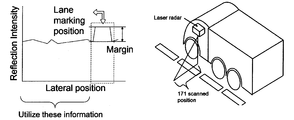
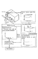
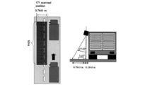
- the figure on the left shows the relationship between reflection intensity and lateral distance.
- the right figure is a figure which shows the aspect of laser beam irradiation. It is the schematic which shows the flow of the whole road surface state estimation apparatus which concerns on this embodiment. It is a block diagram which shows the production
- FIG. 8 is a graph showing the relationship between the reflection intensity and the scanning position (position of each irradiation point) in FIG. It is a figure explaining decomposition
- A is a low frequency signal and D is a high frequency signal.
- Fig. 4 shows multi-stage signal decomposition using a filter bank. The frequency bands separated in each decomposition stage are shown. It is a figure explaining decomposition
- a road surface state estimation apparatus is a light projecting unit that irradiates a laser beam so as to scan on a road surface, and a light receiving unit that acquires a reflection intensity value corresponding to each irradiation point on the road surface. And a road surface state discriminator that discriminates the road surface state using the reflection intensity value.
- the road surface state estimation apparatus includes a two-dimensional scan type laser radar (LIDAR), a computer (an input unit, an output unit, a storage unit such as a RAM and a ROM, a processing unit mainly composed of a CPU) and the like as hardware configurations. ) And.
- the laser radar includes a light projecting unit and a light receiving unit.
- the light projecting unit includes a laser diode, a driving unit for emitting laser light from the laser diode, and an optical system for scanning (such as a mirror).
- the light receiving unit includes a photodetector (photodiode) that detects reflected light from the measurement target (road surface), and the reflection intensity is acquired from the output of the photodiode. Since the configuration of the laser radar itself is well known to those skilled in the art, a detailed description thereof will be omitted.
- the road surface state discriminator can be composed of a computer.
- the road surface state discriminator is generated by machine learning using multiple multipoint reflection intensity value sets acquired for multiple road surfaces with different known road surface states as learning data, and acquired for road surfaces with unknown road surface states Using the set multi-point reflection intensity value as an input, the road surface condition is determined and output.
- the multipoint reflection intensity value set (in the embodiment described later, the reflection intensity value at 171 points) is the irradiation position and reflection intensity in the perspective direction (along the scanning line) with reference to the light projecting portion depending on the road surface state. Defines the relationship with the value.
- a large number of reflection intensity values (multi-point reflection intensity value sets) at a large number of irradiation points are used for machine learning, and measurement data comprising the same multi-point reflection intensity value set is used as an input to classify road surface conditions.
- a laser radar is mounted on the vehicle, and the road surface is irradiated while scanning the laser beam obliquely downward in the lateral width direction of the vehicle from the light projecting unit.
- the laser beam is scanned and transmitted over a predetermined range including the width of the white line in a direction crossing the road surface toward the side of the vehicle.
- the laser reflected light reflected by the road surface is received by the light receiving unit, and the reflection intensity corresponding to each irradiation position of the laser light is acquired.
- white line recognition is performed by measuring the reflection intensity of a white line using a laser radar (Patent Document 1, Non-Patent Document 2).
- This white line recognition uses a difference in reflection intensity to detect a white line because the white line and road asphalt have different reflectivities. Since the white line is mixed with glass beads, the reflection intensity of the white line part is larger than the reflection intensity of the asphalt part due to retroreflection of the glass beads. Therefore, when the horizontal distance is taken along the horizontal axis (scanning direction) and the reflection intensity is taken along the vertical axis, the left side of FIG. 1 is obtained.
- Patent Literature 1 and Non-Patent Literature 2 can be referred to.
- the road surface state can be estimated simultaneously using information acquired in white line recognition, and no new device or component is required.
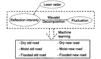
- the road surface state estimation method uses a laser radar reflection intensity and a road surface roughness component extracted from the reflection intensity, and wavelet decomposition is used to extract the road surface roughness component.
- the machine learning is used for road surface discrimination. Aiming to distinguish six types of road surface conditions: dry, wet, and submerged, and two types of road surface quality: new asphalt and aged asphalt. An overall view of a road surface state discriminator using machine learning is shown in FIG.
- the road surface state estimation method considers the positional relationship and the mechanical properties of laser light reflection by using multipoint reflection intensity values included in the measurement range. Depending on the road surface condition, it is conceivable that the reflection intensity value approaches at different places between different road surfaces. Therefore, the feature amount is further increased using the road surface roughness component as an index, and this road surface roughness index is classified by the spatial frequency of the road surface. Therefore, what was calculated using wavelet was defined.
- the road surface state is estimated by using a naive Bayes estimator as a machine learning method for the feature quantity prepared in this way. While traveling, the number of feature values of multipoint reflection intensity values used for road surface state estimation may differ depending on the presence or absence of a white line (if there is a white line, feature quantity data corresponding to the white line is removed, as will be described later) ) The naive Bayes estimator can be applied well even if there is a partial loss of feature data.
- the reflection characteristics of a laser beam by a water film will be described.
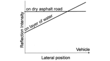
- the laser light is reflected in all directions by the scattering effect, but on the road surface covered with the water film, the reflected light has directionality due to regular reflection in addition to the scattering effect. Therefore, although the reflection intensity is low at the distal side (the side far from the light source), strong laser light reflection due to regular reflection occurs at the proximal side (side near the light source). This reflection intensity characteristic is shown in FIG.
- Reflection intensity is high because there is no absorption into the water film on the dry road surface.
- laser light is absorbed into the water film regardless of whether it is distal or proximal.
- the reflection intensity is lower than that of the road surface. This reflection intensity characteristic is shown in FIG.
- the reflection state varies depending on the mechanical properties of the road surface.
- For aged asphalt and new asphalt organize in dry, wet, submerged, and vehicle distal and vehicle proximal areas.
- the new asphalt has a higher reflection intensity than the aged asphalt.
- the wet road surface absorbs laser light into the water film, resulting in a decrease in reflection intensity.However, when the water film becomes thicker and becomes a flooded road surface, the reflection intensity approaches that of regular road reflection. To rise. In addition to these characteristics, the reflection intensity tends to gradually decrease as the distance from the laser beam emitting portion of the laser radar increases.
- FIG. 8 is a graph showing the relationship between the reflection intensity and the scanning position.
- the farthest data within the effective data range is taken as the origin, and the range up to the laser radar position is taken as the range of the horizontal axis.
- the reflection intensity can be expressed as a function of position by the mechanical properties of the road surface.
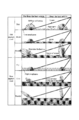
- the reflection intensity value also includes a wavelength component corresponding to the road surface wavelength in the scanning direction. More specifically, scanning is performed according to the characteristics of the spatial frequency (with the addition of laser reflection characteristics): “The larger the macro, the greater the undulation of the entire road surface”, and “The smaller the surface, the micro (particle) unevenness of the road surface”. It is measured as the difference in size of the reflection intensity value in the direction (see FIG. 15).
- This wavelength component is extracted by subjecting the reflection intensity value to discrete wavelet decomposition (FIGS. 9A to 9D). It is also possible to acquire a road surface roughness index using continuous wavelet analysis. By using discrete wavelet analysis, the amount of calculation can be reduced compared to continuous wavelet analysis. The reduction in the calculation amount leads to a reduction in processing cost. In the discrete wavelet analysis according to the present embodiment, the Mallat algorithm is used.
- FIG. 9A is a diagram for explaining signal decomposition.
- A is a low frequency signal and D is a high frequency signal.
- FIG. 9B shows multistage signal decomposition using a filter bank. At each stage, the low frequency component and the high frequency component are separated.
- FIG. 9C shows the frequency bands that are separated at each decomposition stage when the original wavelet is separated three times.
- f n is the center frequency of the mother wavelet.
- the wavelet frequency is usually calculated from a pseudo frequency corresponding to the scale.
- the relationship between frequency and scale is as follows. Fa: pseudo frequency, Fn: center frequency of wavelet (0.66667 Hz in 'db2'), a: scale, ⁇ : sampling period (distance between scanning positions is 0.0045 m).
- FIG. 9A is a diagram for explaining signal decomposition.
- A is a low frequency signal and D is a high frequency signal.
- FIG. 9B shows multistage signal decomposition using a filter bank. At each stage,
- 9D shows decomposition of the reflection intensity (dry state) by the discrete wavelet analysis according to this embodiment.
- the decomposition is performed five times.
- Signal D1 represents road roughness at fine details and signal D5 represents road roughness at low resolution.
- the spatial frequencies included in each high frequency signal are shown in Table 3 (described later).
- the road surface roughness index is obtained by taking the sum of the wavelength bands to be included as the road surface roughness. Therefore, data with n reflection intensity values can be obtained in each scan, whereas one data with road surface roughness can be obtained.
- this road surface roughness index as a road surface feature amount as a variable after the multipoint reflection intensity value, the road surface state estimation accuracy is improved.
- Table 1 summarizes laser light absorption, total reflection, and road surface roughness indices for six road surface conditions. In Table 1, ⁇ indicates strong, X indicates weak, and ⁇ indicates an intermediate value.
- naive Bayes estimator is used as supervised machine learning, and is effective when data according to the Bayes distribution is obtained for each class to be distinguished. It is a technique.
- a reflection intensity value and a road surface roughness index obtained as a result of discrete wavelet decomposition are calculated from the obtained laser radar data.
- n is the number of reflection intensities
- m is the number of road surface roughness indices
- the multipoint reflection intensity value of 171 points expresses the scanning position and reflection intensity from the distal to the proximal as function values.
- the time when the white line is not included in the scanning range is 171 data, and when the white line is included in the scanning range, the processing removes the white line intensity at the scanning position corresponding to the white line from the estimated range. Since the number of feature variables can be changed in this way, a naive Bayes estimator is used as a machine learning method that can cope with the change. Furthermore, it aims at improving estimation accuracy by adding a road surface roughness index after the multipoint reflection intensity value.
- the measurement road surfaces are classified by calculating equations (1) and (2) in real time.
- the position of the white line is recognized based on the road surface obtained from the laser radar and the white line reflection intensity value (see Patent Document 1 and Non-Patent Document 2).
- the white line portion is excluded from the road surface state estimation region based on the white line position information obtained by white line detection based on Patent Document 1 and Non-Patent Document 2. Specifically, from the number of data included in the current scanning range (171 points of data), if a white line is included, the number of data for the white line region (l) is subtracted. The number of multipoint reflection intensity values determined as a result is first set as the number of feature amounts defined at that time.
- a reflection intensity value (n ⁇ 1, where l is the number of data on the white line) and a road surface roughness index (m) based on the reflection intensity value are calculated from the measurement data.
- the road surface is classified by the naive Bayes estimator.
- the data processing apparatus can be configured by a computer (including a hardware configuration such as an input unit, an output unit, a storage unit, and a calculation unit, and predetermined software).
- the test mainly serves as a data storage device that stores various data.
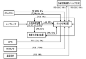
- a laser radar road surface state estimation system and a data logger device for collecting these data were mounted on a trailer type truck, and measurements were taken during business travel.
- Laser radar used for white line recognition and road surface condition estimation is installed on the ceiling of the truck.
- a GPS receiver, a weather recording camera, and a temperature / humidity sensor are installed for environmental recording when performing long-term measurement, and these data are recorded in a data logger.
- the laser radar As the laser radar, a scanning laser radar manufactured by Denso Corporation was used.
- the specifications of the laser radar are as follows. It should be noted that these specifications are only examples of laser radars that can be used in the present invention.
- the number of scanning points on one scanning line in the maximum detection area ( ⁇ 18 [deg]) of the laser radar is 451 points.
- 17.02-3.42 Data of 171 points corresponding to the irradiation angle of [deg] is acquired.
- the distance in the horizontal direction corresponding to 171 points is 0.7641 m.
- the reflected light corresponding to each of the 171 points (irradiation positions) is received, and the reflection intensity at 171 points is acquired.
- the measurement vehicle travels on the road surface at 50-60 km / h, and the sampling frequency of the laser radar is 10 Hz.
- An example of the reflection intensity result obtained by measuring the road surface with the laser radar at this time is shown in FIG.
- the horizontal axis is the horizontal distance, and the vertical axis is the time.
- the reflection intensity is actually displayed in a color scale (luminance value), it is in gray scale due to limitations of the patent drawing.
- FIG. 13 is a reflection intensity map obtained by 100 scans acquired during a 10-second run on an aged asphalt / dry road surface. The portion with high density represents the reflection intensity from the white line portion.
- the six conditions estimated in this test are “Aged asphalt / dry road surface”, “Aged asphalt / wet road surface”, “Aged asphalt / submersion road surface”, “New asphalt / dry road surface”, “New asphalt / wet road surface”. There are six types of "new asphalt / flooding surface”.
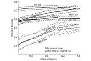
- FIG. 14 shows the reflection intensities obtained as shown in FIG. 13 in which the horizontal axis represents the scan position and the vertical axis represents the reflection intensity.
- the reflection intensity on the road surface under the six conditions shows such a value with respect to the scan position.
- the reflection intensity of dry / new asphalt and wet / aged asphalt, and the reflection intensity of wet / new asphalt and submersion / new asphalt show similar values, but it can be confirmed that they are separated under other conditions.
- wet and aged asphalt had a low recognition rate of 27.26% and submerged and new asphalt were 21.86%, which combined the reflection intensity value and the road surface roughness index.
- the recognition rate was greatly improved, with 93.21% wet and aged asphalt and 56.43% flooded and new asphalt, confirming the effect of adding road surface roughness index as road surface feature amount.
- the discrimination between dry and wet which was the object of this embodiment, was a recognition rate of 92% or more.
- the recognition rate was over 92% for new asphalt and over 93% for aged asphalt.
- the recognition rate of submergence and new asphalt is low, but this is because the correct data of the road surface condition is determined from the weather camera data, so there is a deviation from the actual in the determination of the water film thickness when switching from wet to submersion This is thought to have occurred.
- the data processing time at this time is 0.06 [sec / scanned data]
- this embodiment aims to develop road surface state estimation technology using laser radar that is used for white line recognition in automatic driving and platooning, and uses laser radar reflection intensity and road surface roughness index to We developed an algorithm to determine road dry / wet by using a naive Bayes estimator for learning.
- the road surface state estimation method using the conventional laser radar uses only the reflection intensity, whereas the multipoint reflection intensity value included in the measurement range is used to determine the positional relationship and the laser. For example, the mechanical properties of light reflection can be considered.
- the feature amount is increased using the road surface roughness component as an index, and wavelet decomposition is used to calculate the swell component related to the road surface roughness in order to classify the road surface roughness index by the spatial frequency of the road surface.
- the road surface state is estimated by using a naive Bayes estimator as a machine learning method for the feature quantity prepared in this way.
- a naive Bayes estimator was selected as a machine learning method that can also be applied to estimation objects whose number of features can change.
- the road surface information required for platooning is Dry / Wet information of asphalt, but using the results obtained by actual vehicle measurements, the conditions of the road surface are not only dry / wet but also dry / wet / flooded and asphalt old and new Road surface discrimination was performed on the expanded six road surfaces. As a result, a recognition rate of 92% or higher was obtained for the dry / wet discrimination required in this project. It was also confirmed that the quality of asphalt can be distinguished from old and new.
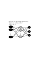
- the road surface state discriminator may be configured from a neural network. As shown in FIG. 16, the neural network includes 171 input nodes (171 multipoint reflection intensity values), output nodes that label three classes (road surface conditions), and 10 hidden nodes. I have.
Landscapes
- Engineering & Computer Science (AREA)
- Physics & Mathematics (AREA)
- General Physics & Mathematics (AREA)
- Remote Sensing (AREA)
- Radar, Positioning & Navigation (AREA)
- Computer Networks & Wireless Communication (AREA)
- Mechanical Engineering (AREA)
- Transportation (AREA)
- Mathematical Physics (AREA)
- Automation & Control Theory (AREA)
- General Health & Medical Sciences (AREA)
- Health & Medical Sciences (AREA)
- Immunology (AREA)
- Biochemistry (AREA)
- Analytical Chemistry (AREA)
- Chemical & Material Sciences (AREA)
- Life Sciences & Earth Sciences (AREA)
- Pathology (AREA)
- Electromagnetism (AREA)
- Regulating Braking Force (AREA)
- Investigating Or Analysing Materials By Optical Means (AREA)
- Control Of Driving Devices And Active Controlling Of Vehicle (AREA)
- Traffic Control Systems (AREA)
- Optical Radar Systems And Details Thereof (AREA)
Abstract
La présente invention comporte une unité d'irradiation de lumière destinée à irradier une lumière laser de manière à balayer une surface de route, une unité de réception de lumière destinée à acquérir des valeurs d'intensité de réflexion correspondant à chaque point irradié sur la surface de route, et un dispositif de détermination de condition de surface de route destiné à déterminer une condition de surface de route à l'aide des valeurs d'intensité de réflexion. Un ensemble de valeurs d'intensité de réflexion acquises pour chaque point irradié sur une surface de route (par la suite désigné par « ensemble de valeurs d'intensité de réflexion multipoint ») définit la relation entre les positions d'irradiation dans la direction lointain-proche depuis l'unité d'irradiation de lumière et les valeurs d'intensité de réflexion, qui sont dépendantes de la condition de route. Le dispositif de détermination de condition de surface de route est créé par l'intermédiaire d'un apprentissage machine utilisant, en tant que données apprises, une pluralité d'ensembles de valeurs d'intensité de réflexion multipoint acquis pour une pluralité de surfaces de route ayant différentes conditions de surface de route connues et détermine et délivre en sortie une condition de surface de route à l'aide de, en tant qu'entrée, un ensemble de valeurs d'intensité de réflexion multipoint acquis pour une surface de route ayant une condition de surface de route inconnue.
Applications Claiming Priority (2)
| Application Number | Priority Date | Filing Date | Title |
|---|---|---|---|
| JP2013-105920 | 2013-05-20 | ||
| JP2013105920A JP6040096B2 (ja) | 2013-05-20 | 2013-05-20 | 路面状態推定装置 |
Publications (1)
| Publication Number | Publication Date |
|---|---|
| WO2014189059A1 true WO2014189059A1 (fr) | 2014-11-27 |
Family
ID=51933612
Family Applications (1)
| Application Number | Title | Priority Date | Filing Date |
|---|---|---|---|
| PCT/JP2014/063388 Ceased WO2014189059A1 (fr) | 2013-05-20 | 2014-05-20 | Dispositif d'estimation de condition de surface de route |
Country Status (2)
| Country | Link |
|---|---|
| JP (1) | JP6040096B2 (fr) |
| WO (1) | WO2014189059A1 (fr) |
Cited By (24)
| Publication number | Priority date | Publication date | Assignee | Title |
|---|---|---|---|---|
| WO2016199285A1 (fr) * | 2015-06-12 | 2016-12-15 | 三菱電機株式会社 | Dispositif et procédé d'aide à la conduite |
| JP2016223780A (ja) * | 2015-05-27 | 2016-12-28 | いすゞ自動車株式会社 | 判別式決定方法及び判別装置 |
| JP2017100656A (ja) * | 2015-12-04 | 2017-06-08 | 株式会社デンソー | 走行制御装置 |
| CN107784261A (zh) * | 2016-08-31 | 2018-03-09 | 北京万集科技股份有限公司 | 一种路面状态检测方法及装置 |
| CN107901912A (zh) * | 2016-10-04 | 2018-04-13 | 现代自动车株式会社 | 基于车辆数据确定道路表面的方法 |
| KR20180093369A (ko) * | 2017-02-13 | 2018-08-22 | 공주대학교 산학협력단 | 라인 스캐닝 도로 노면 기상 상태 측정 장치 및 방법 |
| EP3536574A1 (fr) * | 2018-03-06 | 2019-09-11 | Pablo Alvarez Troncoso | Système de commande de véhicule |
| US10460053B2 (en) | 2017-04-24 | 2019-10-29 | Toyota Research Institute, Inc. | Systems and methods for surface property identification using waveform classification |
| WO2020022473A1 (fr) * | 2018-07-26 | 2020-01-30 | 国立大学法人 東京大学 | Dispositif de mesure, système de mesure, programme de mesure et procédé de mesure |
| CN111114550A (zh) * | 2018-10-30 | 2020-05-08 | 长城汽车股份有限公司 | 车辆控制方法和控制装置及车辆和存储介质 |
| JP2020106443A (ja) * | 2018-12-28 | 2020-07-09 | スタンレー電気株式会社 | 路面状態検知システム及び路面状態検知方法 |
| CN111448477A (zh) * | 2017-10-13 | 2020-07-24 | 密歇根大学董事会 | 材料感测式光成像、检测和测距(lidar)系统 |
| WO2021007038A1 (fr) | 2019-07-09 | 2021-01-14 | Waymo Llc | Incorporation de forme d'onde laser |
| JPWO2020105166A1 (ja) * | 2018-11-22 | 2021-02-15 | 三菱電機株式会社 | 障害物検知装置 |
| CN112841742A (zh) * | 2021-01-18 | 2021-05-28 | 河南中烟工业有限责任公司 | 基于预抽吸动作捕捉的加热使能控制方法 |
| CN113311444A (zh) * | 2021-06-22 | 2021-08-27 | 山东高速建设管理集团有限公司 | 一种水膜识别与处理装置及其使用方法 |
| US20210283973A1 (en) * | 2020-03-12 | 2021-09-16 | Deere & Company | Method and system for estimating surface roughness of ground for an off-road vehicle to control steering |
| US11678599B2 (en) | 2020-03-12 | 2023-06-20 | Deere & Company | Method and system for estimating surface roughness of ground for an off-road vehicle to control steering |
| US11685381B2 (en) | 2020-03-13 | 2023-06-27 | Deere & Company | Method and system for estimating surface roughness of ground for an off-road vehicle to control ground speed |
| US11684005B2 (en) | 2020-03-06 | 2023-06-27 | Deere & Company | Method and system for estimating surface roughness of ground for an off-road vehicle to control an implement |
| US11718304B2 (en) | 2020-03-06 | 2023-08-08 | Deere & Comoanv | Method and system for estimating surface roughness of ground for an off-road vehicle to control an implement |
| US11753016B2 (en) | 2020-03-13 | 2023-09-12 | Deere & Company | Method and system for estimating surface roughness of ground for an off-road vehicle to control ground speed |
| US11772647B2 (en) * | 2016-06-24 | 2023-10-03 | Jaguar Land Rover Limited | Control system for a vehicle |
| US12235112B1 (en) * | 2021-09-30 | 2025-02-25 | Zoox, Inc. | Monitoring map data for validation of vehicle systems |
Families Citing this family (11)
| Publication number | Priority date | Publication date | Assignee | Title |
|---|---|---|---|---|
| CN109689463B (zh) * | 2016-09-13 | 2022-03-15 | 松下知识产权经营株式会社 | 路面状态预测系统、驾驶支援系统、路面状态预测方法以及数据分发方法 |
| WO2018180081A1 (fr) * | 2017-03-29 | 2018-10-04 | パイオニア株式会社 | Dispositif d'identification d'un élément au sol détérioré, système d'identification d'un élément au sol détérioré, procédé d'identification d'un élément au sol détérioré, programme d'identification d'un élément au sol détérioré et support d'enregistrement lisible par ordinateur contenant un programme d'identification d'un élément au sol détérioré |
| KR101958931B1 (ko) * | 2017-10-24 | 2019-07-02 | 인천대학교 산학협력단 | 레이더 검출 데이터를 이용한 도로 상태 식별 장치 및 이의 동작 방법 |
| JPWO2019107353A1 (ja) * | 2017-11-30 | 2020-12-17 | パイオニア株式会社 | 地図データのデータ構造 |
| WO2019216393A1 (fr) * | 2018-05-10 | 2019-11-14 | パナソニックIpマネジメント株式会社 | Procédé d'évaluation de l'état d'un revêtement routier, dispositif d'évaluation de l'état d'un revêtement routier et système d'évaluation de l'état d'un revêtement routier |
| CN110441269A (zh) * | 2019-08-13 | 2019-11-12 | 江苏东交工程检测股份有限公司 | 标线反光检测方法、装置、设备及存储介质 |
| JP7383247B2 (ja) * | 2019-11-28 | 2023-11-20 | 国立研究開発法人宇宙航空研究開発機構 | 情報処理システム、情報処理装置、情報処理方法、及びプログラム |
| JP7021798B1 (ja) | 2020-12-04 | 2022-02-17 | 国立研究開発法人土木研究所 | 学習済みモデル生成方法、路面滑り摩擦係数推定装置、路面滑り摩擦係数推定プログラムおよび路面滑り摩擦係数推定方法 |
| KR102593030B1 (ko) * | 2021-01-25 | 2023-10-23 | 한남대학교 산학협력단 | 인공신경망을 사용한 노면 확인 시스템 |
| US12172649B1 (en) * | 2022-03-31 | 2024-12-24 | Zoox, Inc. | Ground profile estimation for sensor data |
| KR20250030518A (ko) | 2022-09-28 | 2025-03-05 | 제이에프이 스틸 가부시키가이샤 | 연산 방법, 제품의 제조 방법, 제품의 관리 방법, 연산 장치, 제품의 제조 설비, 계측 방법, 계측 시스템, 계측 장치, 교사 데이터의 작성 방법, 교사 데이터, 모델의 생성 방법, 프로그램 및 기억 매체 |
Citations (5)
| Publication number | Priority date | Publication date | Assignee | Title |
|---|---|---|---|---|
| JPH0454600A (ja) * | 1990-06-21 | 1992-02-21 | Mazda Motor Corp | 車両用警報装置 |
| JP2009199154A (ja) * | 2008-02-19 | 2009-09-03 | Ihi Corp | 水溜まり検出装置、無人走行車両及び水溜まり検出方法 |
| WO2011095605A1 (fr) * | 2010-02-04 | 2011-08-11 | Delta Dansk Elektronik, Lys & Akustik | Appareil et procédé de mesure de la rétroréflectivité d'une surface |
| JP2011174794A (ja) * | 2010-02-24 | 2011-09-08 | Kyushu Institute Of Technology | 路面状態検出装置及び方法 |
| WO2011158306A1 (fr) * | 2010-06-18 | 2011-12-22 | 本田技研工業株式会社 | Système de classification des réflectances de la surface des routes |
-
2013
- 2013-05-20 JP JP2013105920A patent/JP6040096B2/ja active Active
-
2014
- 2014-05-20 WO PCT/JP2014/063388 patent/WO2014189059A1/fr not_active Ceased
Patent Citations (5)
| Publication number | Priority date | Publication date | Assignee | Title |
|---|---|---|---|---|
| JPH0454600A (ja) * | 1990-06-21 | 1992-02-21 | Mazda Motor Corp | 車両用警報装置 |
| JP2009199154A (ja) * | 2008-02-19 | 2009-09-03 | Ihi Corp | 水溜まり検出装置、無人走行車両及び水溜まり検出方法 |
| WO2011095605A1 (fr) * | 2010-02-04 | 2011-08-11 | Delta Dansk Elektronik, Lys & Akustik | Appareil et procédé de mesure de la rétroréflectivité d'une surface |
| JP2011174794A (ja) * | 2010-02-24 | 2011-09-08 | Kyushu Institute Of Technology | 路面状態検出装置及び方法 |
| WO2011158306A1 (fr) * | 2010-06-18 | 2011-12-22 | 本田技研工業株式会社 | Système de classification des réflectances de la surface des routes |
Non-Patent Citations (1)
| Title |
|---|
| MITSUYASU MATSUURA ET AL.: "Tairetsu Soko ni Okeru Laser Radar Hakusen Kenchi System (2nd report", PREPRINTS OF MEETING ON AUTOMOTIVE ENGINEERS, 29 September 2010 (2010-09-29), pages 1 - 4 * |
Cited By (41)
| Publication number | Priority date | Publication date | Assignee | Title |
|---|---|---|---|---|
| JP2016223780A (ja) * | 2015-05-27 | 2016-12-28 | いすゞ自動車株式会社 | 判別式決定方法及び判別装置 |
| JPWO2016199285A1 (ja) * | 2015-06-12 | 2017-10-19 | 三菱電機株式会社 | 運転支援装置および運転支援方法 |
| CN107615348A (zh) * | 2015-06-12 | 2018-01-19 | 三菱电机株式会社 | 驾驶辅助装置及驾驶辅助方法 |
| WO2016199285A1 (fr) * | 2015-06-12 | 2016-12-15 | 三菱電機株式会社 | Dispositif et procédé d'aide à la conduite |
| DE112015006613B4 (de) * | 2015-06-12 | 2025-03-13 | Mitsubishi Electric Corporation | Fahrunterstützungsvorrichtung und Fahrunterstützungsverfahren |
| JP2017100656A (ja) * | 2015-12-04 | 2017-06-08 | 株式会社デンソー | 走行制御装置 |
| US11772647B2 (en) * | 2016-06-24 | 2023-10-03 | Jaguar Land Rover Limited | Control system for a vehicle |
| CN107784261B (zh) * | 2016-08-31 | 2020-04-28 | 北京万集科技股份有限公司 | 一种路面状态检测方法及装置 |
| CN107784261A (zh) * | 2016-08-31 | 2018-03-09 | 北京万集科技股份有限公司 | 一种路面状态检测方法及装置 |
| CN107901912A (zh) * | 2016-10-04 | 2018-04-13 | 现代自动车株式会社 | 基于车辆数据确定道路表面的方法 |
| CN107901912B (zh) * | 2016-10-04 | 2021-07-13 | 现代自动车株式会社 | 基于车辆数据确定道路表面的方法 |
| KR20180093369A (ko) * | 2017-02-13 | 2018-08-22 | 공주대학교 산학협력단 | 라인 스캐닝 도로 노면 기상 상태 측정 장치 및 방법 |
| KR101961776B1 (ko) | 2017-02-13 | 2019-07-17 | 공주대학교 산학협력단 | 라인 스캐닝 도로 노면 기상 상태 측정 장치 및 방법 |
| US10460053B2 (en) | 2017-04-24 | 2019-10-29 | Toyota Research Institute, Inc. | Systems and methods for surface property identification using waveform classification |
| CN111448477A (zh) * | 2017-10-13 | 2020-07-24 | 密歇根大学董事会 | 材料感测式光成像、检测和测距(lidar)系统 |
| CN111448477B (zh) * | 2017-10-13 | 2024-01-05 | 密歇根大学董事会 | 材料感测式光成像、检测和测距系统 |
| US12032190B2 (en) | 2017-10-13 | 2024-07-09 | The Regents Of The University Of Michigan | Material-sensing light imaging, detection, and ranging (LIDAR) systems |
| EP3536574A1 (fr) * | 2018-03-06 | 2019-09-11 | Pablo Alvarez Troncoso | Système de commande de véhicule |
| WO2019170940A3 (fr) * | 2018-03-06 | 2019-10-31 | Pablo Alvarez Troncoso | Système de commande d'un véhicule |
| US11874225B2 (en) | 2018-07-26 | 2024-01-16 | The University Of Tokyo | Measurement device, measurement system, measurement program, and measurement method |
| CN112771367A (zh) * | 2018-07-26 | 2021-05-07 | 国立大学法人东京大学 | 测量装置、测量系统、测量程序以及测量方法 |
| JPWO2020022473A1 (ja) * | 2018-07-26 | 2021-08-02 | 国立大学法人 東京大学 | 計測装置、計測システム、計測プログラム、及び計測方法。 |
| WO2020022473A1 (fr) * | 2018-07-26 | 2020-01-30 | 国立大学法人 東京大学 | Dispositif de mesure, système de mesure, programme de mesure et procédé de mesure |
| CN111114550A (zh) * | 2018-10-30 | 2020-05-08 | 长城汽车股份有限公司 | 车辆控制方法和控制装置及车辆和存储介质 |
| CN111114550B (zh) * | 2018-10-30 | 2021-11-23 | 长城汽车股份有限公司 | 车辆控制方法和控制装置及车辆和存储介质 |
| JPWO2020105166A1 (ja) * | 2018-11-22 | 2021-02-15 | 三菱電機株式会社 | 障害物検知装置 |
| JP2020106443A (ja) * | 2018-12-28 | 2020-07-09 | スタンレー電気株式会社 | 路面状態検知システム及び路面状態検知方法 |
| JP7273505B2 (ja) | 2018-12-28 | 2023-05-15 | スタンレー電気株式会社 | 路面状態検知システム及び路面状態検知方法 |
| WO2021007038A1 (fr) | 2019-07-09 | 2021-01-14 | Waymo Llc | Incorporation de forme d'onde laser |
| EP3994486A4 (fr) * | 2019-07-09 | 2023-07-05 | Waymo LLC | Incorporation de forme d'onde laser |
| US11684005B2 (en) | 2020-03-06 | 2023-06-27 | Deere & Company | Method and system for estimating surface roughness of ground for an off-road vehicle to control an implement |
| US11718304B2 (en) | 2020-03-06 | 2023-08-08 | Deere & Comoanv | Method and system for estimating surface roughness of ground for an off-road vehicle to control an implement |
| US11678599B2 (en) | 2020-03-12 | 2023-06-20 | Deere & Company | Method and system for estimating surface roughness of ground for an off-road vehicle to control steering |
| US11667171B2 (en) | 2020-03-12 | 2023-06-06 | Deere & Company | Method and system for estimating surface roughness of ground for an off-road vehicle to control steering |
| US20210283973A1 (en) * | 2020-03-12 | 2021-09-16 | Deere & Company | Method and system for estimating surface roughness of ground for an off-road vehicle to control steering |
| US11685381B2 (en) | 2020-03-13 | 2023-06-27 | Deere & Company | Method and system for estimating surface roughness of ground for an off-road vehicle to control ground speed |
| US11753016B2 (en) | 2020-03-13 | 2023-09-12 | Deere & Company | Method and system for estimating surface roughness of ground for an off-road vehicle to control ground speed |
| CN112841742B (zh) * | 2021-01-18 | 2023-11-21 | 河南中烟工业有限责任公司 | 基于预抽吸动作捕捉的加热使能控制方法 |
| CN112841742A (zh) * | 2021-01-18 | 2021-05-28 | 河南中烟工业有限责任公司 | 基于预抽吸动作捕捉的加热使能控制方法 |
| CN113311444A (zh) * | 2021-06-22 | 2021-08-27 | 山东高速建设管理集团有限公司 | 一种水膜识别与处理装置及其使用方法 |
| US12235112B1 (en) * | 2021-09-30 | 2025-02-25 | Zoox, Inc. | Monitoring map data for validation of vehicle systems |
Also Published As
| Publication number | Publication date |
|---|---|
| JP2014228300A (ja) | 2014-12-08 |
| JP6040096B2 (ja) | 2016-12-07 |
Similar Documents
| Publication | Publication Date | Title |
|---|---|---|
| JP6040096B2 (ja) | 路面状態推定装置 | |
| CN105717514B (zh) | 利用激光雷达传感器的路面反射性检测 | |
| CN111352110B (zh) | 处理雷达数据的方法和装置 | |
| Benedek et al. | Positioning and perception in LIDAR point clouds | |
| Aki et al. | Road surface recognition using laser radar for automatic platooning | |
| EP2118818B1 (fr) | Alerte de franchissement involontaire de ligne par vidéo | |
| KR101762504B1 (ko) | 레이저 거리 센서를 이용한 바닥 장애물 검출 방법 | |
| Vatani Nezafat et al. | Transfer learning using deep neural networks for classification of truck body types based on side-fire lidar data | |
| Akita et al. | Object tracking and classification using millimeter-wave radar based on LSTM | |
| CN103886757A (zh) | 用于自动分类运动中的车辆的方法 | |
| US7466860B2 (en) | Method and apparatus for classifying an object | |
| KR102401382B1 (ko) | 라이다를 이용한 노면 검출 시스템 및 그를 이용한 노면의 검출 방법 | |
| Certad et al. | Road markings segmentation from lidar point clouds using reflectivity information | |
| KR100962329B1 (ko) | 스테레오 카메라 영상으로부터의 지면 추출 방법과 장치 및이와 같은 방법을 구현하는 프로그램이 기록된 기록매체 | |
| CN102589515A (zh) | 一种雾天距离测量方法及装置、距离预警方法及装置 | |
| CN116500647A (zh) | 一种基于激光雷达的车辆检测方法 | |
| CN112987015B (zh) | 一种船舶检测方法、装置及激光雷达系统 | |
| JP6851111B2 (ja) | 踏切障害物検知装置 | |
| Cai et al. | Measurement of vehicle queue length based on video processing in intelligent traffic signal control system | |
| Yasin et al. | Travel time measurement in real-time using automatic number plate recognition for Malaysian environment | |
| Cowan et al. | Investigation of adas/ads sensor and system response to rainfall rate | |
| CN116587978A (zh) | 一种基于车载显示屏的碰撞预警方法及系统 | |
| WO2020258065A1 (fr) | Procédé de détection météorologique basé sur un radar à ondes millimétriques, radar à ondes millimétriques et plate-forme mobile | |
| CN112014822B (zh) | 车载雷达测量数据识别方法、装置、介质和电子装置 | |
| CN116125440A (zh) | 用于确定激光雷达传感器的最大作用范围的方法以及设备 |
Legal Events
| Date | Code | Title | Description |
|---|---|---|---|
| 121 | Ep: the epo has been informed by wipo that ep was designated in this application |
Ref document number: 14800555 Country of ref document: EP Kind code of ref document: A1 |
|
| NENP | Non-entry into the national phase |
Ref country code: DE |
|
| 122 | Ep: pct application non-entry in european phase |
Ref document number: 14800555 Country of ref document: EP Kind code of ref document: A1 |