WO2014189081A1 - Tôles destinées à des contenants et leur procédé de production - Google Patents
Tôles destinées à des contenants et leur procédé de production Download PDFInfo
- Publication number
- WO2014189081A1 WO2014189081A1 PCT/JP2014/063478 JP2014063478W WO2014189081A1 WO 2014189081 A1 WO2014189081 A1 WO 2014189081A1 JP 2014063478 W JP2014063478 W JP 2014063478W WO 2014189081 A1 WO2014189081 A1 WO 2014189081A1
- Authority
- WO
- WIPO (PCT)
- Prior art keywords
- layer
- amount
- plating
- steel plate
- film layer
- Prior art date
- Legal status (The legal status is an assumption and is not a legal conclusion. Google has not performed a legal analysis and makes no representation as to the accuracy of the status listed.)
- Ceased
Links
Images


Classifications
-
- C—CHEMISTRY; METALLURGY
- C25—ELECTROLYTIC OR ELECTROPHORETIC PROCESSES; APPARATUS THEREFOR
- C25D—PROCESSES FOR THE ELECTROLYTIC OR ELECTROPHORETIC PRODUCTION OF COATINGS; ELECTROFORMING; APPARATUS THEREFOR
- C25D5/00—Electroplating characterised by the process; Pretreatment or after-treatment of workpieces
- C25D5/10—Electroplating with more than one layer of the same or of different metals
- C25D5/12—Electroplating with more than one layer of the same or of different metals at least one layer being of nickel or chromium
-
- C—CHEMISTRY; METALLURGY
- C23—COATING METALLIC MATERIAL; COATING MATERIAL WITH METALLIC MATERIAL; CHEMICAL SURFACE TREATMENT; DIFFUSION TREATMENT OF METALLIC MATERIAL; COATING BY VACUUM EVAPORATION, BY SPUTTERING, BY ION IMPLANTATION OR BY CHEMICAL VAPOUR DEPOSITION, IN GENERAL; INHIBITING CORROSION OF METALLIC MATERIAL OR INCRUSTATION IN GENERAL
- C23C—COATING METALLIC MATERIAL; COATING MATERIAL WITH METALLIC MATERIAL; SURFACE TREATMENT OF METALLIC MATERIAL BY DIFFUSION INTO THE SURFACE, BY CHEMICAL CONVERSION OR SUBSTITUTION; COATING BY VACUUM EVAPORATION, BY SPUTTERING, BY ION IMPLANTATION OR BY CHEMICAL VAPOUR DEPOSITION, IN GENERAL
- C23C2/00—Hot-dipping or immersion processes for applying the coating material in the molten state without affecting the shape; Apparatus therefor
- C23C2/04—Hot-dipping or immersion processes for applying the coating material in the molten state without affecting the shape; Apparatus therefor characterised by the coating material
- C23C2/08—Tin or alloys based thereon
-
- C—CHEMISTRY; METALLURGY
- C23—COATING METALLIC MATERIAL; COATING MATERIAL WITH METALLIC MATERIAL; CHEMICAL SURFACE TREATMENT; DIFFUSION TREATMENT OF METALLIC MATERIAL; COATING BY VACUUM EVAPORATION, BY SPUTTERING, BY ION IMPLANTATION OR BY CHEMICAL VAPOUR DEPOSITION, IN GENERAL; INHIBITING CORROSION OF METALLIC MATERIAL OR INCRUSTATION IN GENERAL
- C23C—COATING METALLIC MATERIAL; COATING MATERIAL WITH METALLIC MATERIAL; SURFACE TREATMENT OF METALLIC MATERIAL BY DIFFUSION INTO THE SURFACE, BY CHEMICAL CONVERSION OR SUBSTITUTION; COATING BY VACUUM EVAPORATION, BY SPUTTERING, BY ION IMPLANTATION OR BY CHEMICAL VAPOUR DEPOSITION, IN GENERAL
- C23C28/00—Coating for obtaining at least two superposed coatings either by methods not provided for in a single one of groups C23C2/00 - C23C26/00 or by combinations of methods provided for in subclasses C23C and C25C or C25D
- C23C28/30—Coatings combining at least one metallic layer and at least one inorganic non-metallic layer
- C23C28/32—Coatings combining at least one metallic layer and at least one inorganic non-metallic layer including at least one pure metallic layer
- C23C28/321—Coatings combining at least one metallic layer and at least one inorganic non-metallic layer including at least one pure metallic layer with at least one metal alloy layer
-
- C—CHEMISTRY; METALLURGY
- C23—COATING METALLIC MATERIAL; COATING MATERIAL WITH METALLIC MATERIAL; CHEMICAL SURFACE TREATMENT; DIFFUSION TREATMENT OF METALLIC MATERIAL; COATING BY VACUUM EVAPORATION, BY SPUTTERING, BY ION IMPLANTATION OR BY CHEMICAL VAPOUR DEPOSITION, IN GENERAL; INHIBITING CORROSION OF METALLIC MATERIAL OR INCRUSTATION IN GENERAL
- C23C—COATING METALLIC MATERIAL; COATING MATERIAL WITH METALLIC MATERIAL; SURFACE TREATMENT OF METALLIC MATERIAL BY DIFFUSION INTO THE SURFACE, BY CHEMICAL CONVERSION OR SUBSTITUTION; COATING BY VACUUM EVAPORATION, BY SPUTTERING, BY ION IMPLANTATION OR BY CHEMICAL VAPOUR DEPOSITION, IN GENERAL
- C23C28/00—Coating for obtaining at least two superposed coatings either by methods not provided for in a single one of groups C23C2/00 - C23C26/00 or by combinations of methods provided for in subclasses C23C and C25C or C25D
- C23C28/30—Coatings combining at least one metallic layer and at least one inorganic non-metallic layer
- C23C28/32—Coatings combining at least one metallic layer and at least one inorganic non-metallic layer including at least one pure metallic layer
- C23C28/322—Coatings combining at least one metallic layer and at least one inorganic non-metallic layer including at least one pure metallic layer only coatings of metal elements only
-
- C—CHEMISTRY; METALLURGY
- C23—COATING METALLIC MATERIAL; COATING MATERIAL WITH METALLIC MATERIAL; CHEMICAL SURFACE TREATMENT; DIFFUSION TREATMENT OF METALLIC MATERIAL; COATING BY VACUUM EVAPORATION, BY SPUTTERING, BY ION IMPLANTATION OR BY CHEMICAL VAPOUR DEPOSITION, IN GENERAL; INHIBITING CORROSION OF METALLIC MATERIAL OR INCRUSTATION IN GENERAL
- C23C—COATING METALLIC MATERIAL; COATING MATERIAL WITH METALLIC MATERIAL; SURFACE TREATMENT OF METALLIC MATERIAL BY DIFFUSION INTO THE SURFACE, BY CHEMICAL CONVERSION OR SUBSTITUTION; COATING BY VACUUM EVAPORATION, BY SPUTTERING, BY ION IMPLANTATION OR BY CHEMICAL VAPOUR DEPOSITION, IN GENERAL
- C23C28/00—Coating for obtaining at least two superposed coatings either by methods not provided for in a single one of groups C23C2/00 - C23C26/00 or by combinations of methods provided for in subclasses C23C and C25C or C25D
- C23C28/30—Coatings combining at least one metallic layer and at least one inorganic non-metallic layer
- C23C28/34—Coatings combining at least one metallic layer and at least one inorganic non-metallic layer including at least one inorganic non-metallic material layer, e.g. metal carbide, nitride, boride, silicide layer and their mixtures, enamels, phosphates and sulphates
-
- C—CHEMISTRY; METALLURGY
- C23—COATING METALLIC MATERIAL; COATING MATERIAL WITH METALLIC MATERIAL; CHEMICAL SURFACE TREATMENT; DIFFUSION TREATMENT OF METALLIC MATERIAL; COATING BY VACUUM EVAPORATION, BY SPUTTERING, BY ION IMPLANTATION OR BY CHEMICAL VAPOUR DEPOSITION, IN GENERAL; INHIBITING CORROSION OF METALLIC MATERIAL OR INCRUSTATION IN GENERAL
- C23C—COATING METALLIC MATERIAL; COATING MATERIAL WITH METALLIC MATERIAL; SURFACE TREATMENT OF METALLIC MATERIAL BY DIFFUSION INTO THE SURFACE, BY CHEMICAL CONVERSION OR SUBSTITUTION; COATING BY VACUUM EVAPORATION, BY SPUTTERING, BY ION IMPLANTATION OR BY CHEMICAL VAPOUR DEPOSITION, IN GENERAL
- C23C28/00—Coating for obtaining at least two superposed coatings either by methods not provided for in a single one of groups C23C2/00 - C23C26/00 or by combinations of methods provided for in subclasses C23C and C25C or C25D
- C23C28/30—Coatings combining at least one metallic layer and at least one inorganic non-metallic layer
- C23C28/34—Coatings combining at least one metallic layer and at least one inorganic non-metallic layer including at least one inorganic non-metallic material layer, e.g. metal carbide, nitride, boride, silicide layer and their mixtures, enamels, phosphates and sulphates
- C23C28/345—Coatings combining at least one metallic layer and at least one inorganic non-metallic layer including at least one inorganic non-metallic material layer, e.g. metal carbide, nitride, boride, silicide layer and their mixtures, enamels, phosphates and sulphates with at least one oxide layer
-
- C—CHEMISTRY; METALLURGY
- C25—ELECTROLYTIC OR ELECTROPHORETIC PROCESSES; APPARATUS THEREFOR
- C25D—PROCESSES FOR THE ELECTROLYTIC OR ELECTROPHORETIC PRODUCTION OF COATINGS; ELECTROFORMING; APPARATUS THEREFOR
- C25D3/00—Electroplating: Baths therefor
- C25D3/02—Electroplating: Baths therefor from solutions
- C25D3/12—Electroplating: Baths therefor from solutions of nickel or cobalt
-
- C—CHEMISTRY; METALLURGY
- C25—ELECTROLYTIC OR ELECTROPHORETIC PROCESSES; APPARATUS THEREFOR
- C25D—PROCESSES FOR THE ELECTROLYTIC OR ELECTROPHORETIC PRODUCTION OF COATINGS; ELECTROFORMING; APPARATUS THEREFOR
- C25D3/00—Electroplating: Baths therefor
- C25D3/02—Electroplating: Baths therefor from solutions
- C25D3/30—Electroplating: Baths therefor from solutions of tin
-
- C—CHEMISTRY; METALLURGY
- C25—ELECTROLYTIC OR ELECTROPHORETIC PROCESSES; APPARATUS THEREFOR
- C25D—PROCESSES FOR THE ELECTROLYTIC OR ELECTROPHORETIC PRODUCTION OF COATINGS; ELECTROFORMING; APPARATUS THEREFOR
- C25D3/00—Electroplating: Baths therefor
- C25D3/02—Electroplating: Baths therefor from solutions
- C25D3/54—Electroplating: Baths therefor from solutions of metals not provided for in groups C25D3/04 - C25D3/50
-
- C—CHEMISTRY; METALLURGY
- C25—ELECTROLYTIC OR ELECTROPHORETIC PROCESSES; APPARATUS THEREFOR
- C25D—PROCESSES FOR THE ELECTROLYTIC OR ELECTROPHORETIC PRODUCTION OF COATINGS; ELECTROFORMING; APPARATUS THEREFOR
- C25D5/00—Electroplating characterised by the process; Pretreatment or after-treatment of workpieces
- C25D5/34—Pretreatment of metallic surfaces to be electroplated
- C25D5/36—Pretreatment of metallic surfaces to be electroplated of iron or steel
-
- C—CHEMISTRY; METALLURGY
- C25—ELECTROLYTIC OR ELECTROPHORETIC PROCESSES; APPARATUS THEREFOR
- C25D—PROCESSES FOR THE ELECTROLYTIC OR ELECTROPHORETIC PRODUCTION OF COATINGS; ELECTROFORMING; APPARATUS THEREFOR
- C25D5/00—Electroplating characterised by the process; Pretreatment or after-treatment of workpieces
- C25D5/48—After-treatment of electroplated surfaces
-
- C—CHEMISTRY; METALLURGY
- C25—ELECTROLYTIC OR ELECTROPHORETIC PROCESSES; APPARATUS THEREFOR
- C25D—PROCESSES FOR THE ELECTROLYTIC OR ELECTROPHORETIC PRODUCTION OF COATINGS; ELECTROFORMING; APPARATUS THEREFOR
- C25D5/00—Electroplating characterised by the process; Pretreatment or after-treatment of workpieces
- C25D5/48—After-treatment of electroplated surfaces
- C25D5/50—After-treatment of electroplated surfaces by heat-treatment
- C25D5/505—After-treatment of electroplated surfaces by heat-treatment of electroplated tin coatings, e.g. by melting
-
- C—CHEMISTRY; METALLURGY
- C25—ELECTROLYTIC OR ELECTROPHORETIC PROCESSES; APPARATUS THEREFOR
- C25D—PROCESSES FOR THE ELECTROLYTIC OR ELECTROPHORETIC PRODUCTION OF COATINGS; ELECTROFORMING; APPARATUS THEREFOR
- C25D7/00—Electroplating characterised by the article coated
-
- C—CHEMISTRY; METALLURGY
- C25—ELECTROLYTIC OR ELECTROPHORETIC PROCESSES; APPARATUS THEREFOR
- C25D—PROCESSES FOR THE ELECTROLYTIC OR ELECTROPHORETIC PRODUCTION OF COATINGS; ELECTROFORMING; APPARATUS THEREFOR
- C25D9/00—Electrolytic coating other than with metals
- C25D9/04—Electrolytic coating other than with metals with inorganic materials
- C25D9/08—Electrolytic coating other than with metals with inorganic materials by cathodic processes
Definitions
- the present invention relates to a steel plate for containers and a method for producing a steel plate for containers.
- container steel plates such as nickel (Ni) plated steel plates, tin (Sn) plated steel plates, tin-based alloy plated steel plates and the like are often used.
- these container steel plates are subjected to rust prevention treatment with chromate using hexavalent chromate or the like in order to ensure adhesion and corrosion resistance between the steel plate and the coating or between the steel plate and the film.
- zirconium (Zr) -phosphorus (P) is an alternative to the rust prevention treatment with chromate that has been applied to steel plates for containers.
- a treatment using a chemical conversion treatment film such as a film has been developed (see, for example, Patent Document 1 below).
- the metal vessel was made resistant to sulfide blackening by using a chromate that forms a dense film even if the amount of the film is small.
- a chemical conversion film such as a zirconium-phosphorus film is used instead of chromate, the film defects increase when the film amount is reduced. For this reason, in order to exhibit excellent corrosion resistance, the amount of coating cannot be reduced, and cost reduction is difficult.
- the present invention has been made in view of the above problems, and the object of the present invention is to use a chemical conversion treatment film to achieve sulfurization blackening resistance and cost reduction. It is providing the manufacturing method of the steel plate for containers and the steel plate for containers.
- the present inventor has intensively studied, and as a result, can form all the above problems by forming an oxide film layer containing tin oxide (SnOx) between the chemical conversion film and the Sn plating layer. discovered. And the summary is as follows.
- a first aspect of the present invention is a substrate in which Ni plating or Fe—Ni alloy plating containing 5 to 150 mg / m 2 of Ni in terms of metal Ni is applied to a steel plate and at least one side of the steel plate.
- Ni plating or Fe—Ni alloy plating containing 5 to 150 mg / m 2 of Ni in terms of metal Ni is applied to a steel plate and at least one side of the steel plate.
- Sn plating 300 to 3000 mg / m 2 in terms of metal Sn is applied, and the Sn plating and at least a part of the underlying Ni layer are alloyed by molten tin treatment.
- the oxide film layer contains the tin oxide in an amount such that the amount of electricity required for reduction of the oxide film layer is 5.5 to 10 mC / cm 2. May be.
- At least one surface of the steel sheet is subjected to Ni plating or Fe—Ni alloy plating, and a base Ni layer containing 5 to 150 mg / m 2 of Ni in the amount of metal Ni is provided.
- the tin plating and at least a part of the underlying Ni layer are alloyed to form an Sn plating layer containing island-shaped Sn, and the surface of the Sn plating layer is surface oxidized to contain tin oxide.
- Forming an oxide film layer, Zr ions of 10 ppm to 10000 ppm, fluoride ions of 10 ppm to 10000 ppm, and 10 ppm to 3000 ppm And phosphate ions below includes 30000ppm and less of nitrate and / or sulfate ions above 100 ppm, a, and the temperature in the chemical conversion treatment solution of less than 5 ° C.
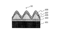
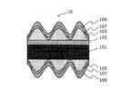
- FIG. 1A and FIG. 1B are explanatory views schematically showing the configuration when the steel plate for containers in this embodiment is viewed from the side.
- the steel plate 10 for containers in the present embodiment includes a steel plate 101, a base Ni layer 103, a Sn plating layer 105, an oxide film layer 107, a chemical conversion film layer 109, Is provided.
- the base Ni layer 103, the Sn plating layer 105, the oxide film layer 107, and the chemical conversion film layer 109 may be formed only on one surface of the steel plate 101 as shown in FIG. 1A, or as shown in FIG. 1B. In this manner, the steel plates 101 may be formed on two surfaces facing each other.
- the steel plate 101 is used as a base material of the container steel plate 10 in the present embodiment.
- the steel plate 101 used in the present embodiment is not particularly limited, and it is possible to use a known steel plate that is usually used as a container material. There are no particular limitations on the manufacturing method and material of these known steel plates, and from the normal steel slab manufacturing process, known processes such as hot rolling, pickling, cold rolling, annealing, and temper rolling are performed. What was manufactured after passing may be sufficient.
- a base Ni layer 103 is formed on the surface of the steel plate 101.
- the underlying Ni layer 103 is a Ni-based plating layer made of Ni or a Fe—Ni alloy containing at least Ni in a metallic Ni amount of 5 to 150 mg / m 2 .
- the underlying Ni layer 103 is formed by applying Ni plating or Fe—Ni alloy plating to the steel plate 101.
- Ni-based plating layer made of Ni or Fe—Ni alloy is formed to ensure paint adhesion, film adhesion, corrosion resistance, and weldability. Since Ni is a highly corrosion-resistant metal, it is possible to improve the corrosion resistance of an alloy layer containing Fe and Sn that is formed during the molten tin treatment described later by Ni plating. The effect of improving the paint adhesion, film adhesion, corrosion resistance, and weldability of the alloy layer with Ni begins to appear when the amount of metallic Ni in the base Ni layer 103 is 5 mg / m 2 or more, and the Ni content increases. The effect of improving the corrosion resistance of the alloy layer is increased. Therefore, the amount of metallic Ni in the base Ni layer 103 is set to 5 mg / m 2 or more.
- the amount of metallic Ni in the base Ni layer 103 is set to 150 mg / m 2 or less. This is because when the amount of metallic Ni in the base Ni layer 103 exceeds 150 mg / m 2 , not only the effects of improving paint adhesion, film adhesion, corrosion resistance and weldability are saturated, but Ni is an expensive metal. For this reason, it is economically disadvantageous to plate more than 150 mg / m 2 of Ni.
- the amount of metallic Ni in the base Ni layer 103 is more preferably 5 to 100 mg / m 2 .
- Ni diffusion plating when Ni diffusion plating is performed, after Ni plating, diffusion treatment is performed in an annealing furnace to form a Ni diffusion layer. Nitriding treatment may be performed before or after the Ni diffusion treatment. Even when nitriding is performed, both the effect of Ni as the underlying Ni layer 103 and the effect of the nitriding layer in this embodiment can be exhibited.
- Ni plating or Fe—Ni alloy plating for example, a publicly known method generally performed in an electroplating method can be used.
- Sn plating layer 105 On the base Ni layer 103, as shown in FIGS. 1A and 1B, an Sn plating layer 105 is formed by Sn plating.
- the Sn plating layer 105 is a plating layer containing 300 to 3000 mg / m 2 of at least Sn in terms of metal Sn.
- Sn plating in this specification includes not only plating with metallic tin, but also metallic tin mixed with irreversible impurities and metallic tin added with trace elements.
- the Sn plating method is not particularly restricted, but for example, a known electroplating method is preferably used. A method of immersing and plating a steel plate in molten Sn may be used.
- the Sn plating layer 105 by the above Sn plating is formed to ensure corrosion resistance and weldability. Since Sn itself has high corrosion resistance, it exhibits excellent corrosion resistance and weldability both as metallic tin and as an alloy formed by the molten tin treatment described below.
- the excellent corrosion resistance of Sn is remarkably improved from the amount of metal Sn of 300 mg / m 2 or more, and the degree of improvement in corrosion resistance increases as the Sn content increases. Therefore, the amount of metallic Sn in the Sn plating layer 105 is set to 300 mg / m 2 or more. Moreover, since the corrosion resistance improving effect is saturated when the amount of metal Sn exceeds 3000 mg / m 2 , the Sn content is set to 3000 mg / m 2 or less from an economical viewpoint.
- Sn with low electric resistance is soft and spreads by pressurizing Sn between the electrodes during welding, so that a stable energization region can be secured, and thus particularly excellent weldability is exhibited.
- This excellent weldability is exhibited when the amount of metal Sn is 100 mg / m 2 or more.
- the weldability improving effect is not saturated.
- the amount of metal Sn is set to 300 mg / m 2 or more and 3000 mg / m 2 or less.
- the amount of metallic Sn in the Sn plating layer 105 is more preferably 300 to 2000 mg / m 2 .
- a molten tin treatment (reflow treatment) is performed.
- the purpose of the molten tin treatment is to melt Sn and alloy it with the underlying steel plate 101 and the underlying Ni layer 103 to form a Sn—Fe or Sn—Fe—Ni alloy layer, thereby improving the corrosion resistance of the alloy layer.
- an Sn alloy made of island-like Sn is formed. This island-shaped Sn alloy can be formed by appropriately controlling the molten tin treatment.
- the surface of the Sn plating layer 105 (the surface opposite to the interface with the underlying Ni layer 103) is oxidized by appropriately controlled molten tin treatment, and an oxide film layer 107 described later becomes an Sn plating layer 105. Formed on top.
- Oxide film layer 107 On the Sn plating layer 105, as shown in FIGS. 1A and 1B, an oxide film layer 107 containing tin oxide is formed. This oxide film layer 107 contains tin oxide in such an amount that the amount of electricity required to reduce the oxide film layer 107 is 0.3 to 10 mC (millicoulomb) / cm 2 . By forming such an oxide film layer 107 on the Sn plating layer 105, it is possible to improve the blackening resistance of the steel plate 10 for containers.
- Sulfidation blackening occurs when metal Sn and sulfur S react to produce black SnS. Therefore, in the case of a container steel plate having a Sn plating layer, sulfur S contained in a container holding such as food reacts with the metal Sn in the Sn plating layer. Therefore, by forming the oxide film layer 107 containing tin oxide on the Sn plating layer 105, diffusion of sulfur atoms S to the interface of the Sn plating layer 105 can be suppressed, and resistance to sulfur blackening is improved. As a result, even when the amount of the chemical conversion coating layer deposited on the oxide coating layer 107 is reduced, excellent anti-sulfur blackening resistance can be realized.
- the sulfur blackening resistance is such that the tin oxide content (tin oxide amount) of the oxide film layer 107 is equal to or more than the amount corresponding to the electric amount of 0.3 mC / cm 2 required for the reduction of the oxide film layer 107. It appears remarkably from the case. Therefore, the amount of tin oxide contained in the oxide film layer 107 is set to be equal to or more than the amount corresponding to the electric amount of 0.3 mC / cm 2 required for the reduction of the oxide film layer 107.
- the oxide film containing tin oxide is a brittle film, and when the amount of adhesion is too large, the chemical conversion treatment film layer 109 formed on the oxide film layer 107 is easily peeled off.
- the amount of tin oxide contained in the oxide film layer 107 corresponds to the amount of electricity 10 mC / cm 2 required for the reduction of the oxide film layer 107. Or less.
- the amount of metal Sn in the oxide film layer 107 is more preferably an amount corresponding to 5.5 to 10 mC / cm 2 .
- the oxide film layer 107 can be formed by performing a molten tin treatment for forming island-shaped Sn in the Sn plating layer 105 at an appropriate temperature for an appropriate time.
- the island shape means a state in which the surface of the underlayer is not completely covered by the upper layer and the underlayer is partially exposed. That is, the “island-like Sn plating layer” refers to a state in which the surface of the underlying Ni layer including alloy plating is not completely covered by the Sn plating layer but is partially exposed.
- the molten tin treatment capable of appropriately forming the Sn plating layer 105 and the oxide film layer 107 is performed at 200 ° C. or higher and 300 ° C.
- the temperature is raised to below °C, and as soon as a metallic luster is obtained, it is rapidly cooled to room temperature (for example, about 50 ° C.) with cold water or the like.
- the chemical conversion coating layer 109 contains at least a metal Zr amount of 1 to 500 mg / m 2 of Zr and a P amount of 0.1 to 100 mg / m 2 of phosphoric acid (in other words, a Zr component and a phosphorus content). And a composite coating layer mainly composed of a zirconium compound.
- the chemical conversion coating layer 109 is a composite coating in which a Zr component and a phosphoric acid component are combined, so that excellent practical performance can be exhibited. .
- the Zr component contained in the chemical conversion coating layer 109 in this embodiment has a function of improving corrosion resistance and adhesion, and further processing adhesion.
- the Zr component in the present embodiment is composed of, for example, a plurality of Zr compounds such as zirconium hydroxide and zirconium fluoride in addition to zirconium oxide and zirconium phosphate. Since such a Zr component is excellent in corrosion resistance and adhesion, the corrosion resistance and adhesion of the steel plate 10 for containers improve as the amount of the Zr component contained in the chemical conversion coating layer 109 increases.
- the content of the Zr component adhering to the oxide film layer 107 as the chemical conversion film layer 109 is 1 mg / m 2 or more in terms of the metal Zr amount, the corrosion resistance and the coating level, etc., which are practically satisfactory. Adhesion is ensured.
- the content of the Zr component increases, the effect of improving the adhesion resistance such as corrosion resistance and coating also increases.
- the content of the Zr component exceeds 500 mg / m 2 in terms of the amount of metal Zr, the chemical conversion treatment film As the layer 109 becomes too thick, the adhesion (mainly due to cohesive failure) of the chemical conversion film itself decreases, and the electrical resistance increases and the weldability decreases.
- the content of Zr component i.e., the content of Zr
- the content of Zr component is a 1mg / m 2 ⁇ 500mg / m 2 by metal Zr content.
- the content of the Zr component is more preferably 2 to 50 mg / m 2 in terms of metal Zr content.
- the chemical conversion treatment film layer 109 further includes a phosphoric acid component formed of one or more phosphoric acid compounds in addition to the Zr component described above.
- the phosphoric acid component in this embodiment has a function of improving corrosion resistance and adhesion, and further processing adhesion.
- the phosphoric acid component in the present embodiment includes iron phosphate, nickel phosphate, tin phosphate formed by reacting with the base (steel plate 101, base Ni layer 103, Sn plating layer 105, oxide film layer 107) and the Zr component. And a single component of phosphoric acid such as zirconium phosphate, or a composite component composed of two or more types of phosphoric acid compounds. Since such a phosphoric acid component is excellent in corrosion resistance and adhesiveness, the corrosion resistance and adhesiveness of the steel plate 10 for containers improve, so that the quantity of the phosphoric acid component formed increases.
- the content of the phosphoric acid component in the chemical conversion coating layer 109 is 0.1 mg / m 2 or more in terms of the amount of P, a level of corrosion resistance and adhesion such as coating that are practically satisfactory are ensured.
- the effect of improving the corrosion resistance and adhesion such as coating is also increased.
- the content of the phosphoric acid component exceeds 100 mg / m 2 in terms of the amount of P, the chemical conversion coating layer 109 becomes too thick and the adhesion (mainly due to cohesive failure) of the chemical conversion coating itself decreases. At the same time, the electrical resistance increases and the weldability decreases.
- the adhesion nonuniformity of a chemical conversion treatment film may appear as an external appearance nonuniformity. Accordingly, the container steel plate 10 in the present embodiment, the content of the phosphoric acid component, and 0.1mg / m 2 ⁇ 100mg / m 2 in the P content.
- the content of the phosphoric acid component is more preferably 0.5 to 30 mg / m 2 in terms of P amount.
- the amount of metal Zr is set to a low bottom film amount such as 2 mg / m 2 . Even in this case, excellent resistance to sulfur blackening can be achieved. As a result, it is possible to further reduce the adhesion amount of the chemical conversion treatment film layer 109, thereby realizing cost reduction.
- the chemical conversion treatment film layer 109 containing such a Zr component and a phosphoric acid component is formed by electrolytic treatment (for example, cathodic electrolytic treatment).
- electrolytic treatment for example, cathodic electrolytic treatment
- a chemical conversion treatment solution containing you may add a phenol resin etc. further to these chemical conversion liquids as needed.
- the temperature of this chemical conversion solution is 5 ° C or higher and lower than 90 ° C.
- the temperature of a chemical conversion liquid is less than 5 degreeC, the formation efficiency of a film
- the temperature of a chemical conversion liquid is 90 degreeC or more, the membrane
- tissue formed is uneven and a defect, a crack, a microcrack, etc. generate
- Such electrolytic treatment is performed at a current density of 1.0 A / dm 2 or more and 100 A / dm 2 or less and an electrolytic treatment time of 0.2 seconds or more and 150 seconds or less.
- a current density of less than 1.0 A / dm 2 is not preferable because it causes a decrease in the amount of the chemical conversion coating layer deposited and a decrease in productivity due to the long electrolytic treatment time required.
- a current density is over 100 A / dm ⁇ 2 >, the adhesion amount of a chemical conversion treatment film layer exceeds a required amount, and is saturated.
- a film with insufficient adhesion is washed away (peeled off) in a washing step such as washing with water after electrolytic conversion treatment.
- the electrolytic treatment time is less than 0.2 seconds, it is not preferable because the coating adhesion amount is reduced and the corrosion resistance, coating adhesion, and the like may be reduced.
- the electrolytic treatment time exceeds 150 seconds, the coating amount exceeds the required amount, and the deposition amount is saturated.
- it is not economical that a film with insufficient adhesion is washed away (peeled off) in a washing step such as washing with water after electrolytic conversion treatment.
- the pH is preferably in the range of 3.1 to 3.7, more preferably around 3.5.
- nitric acid or ammonia may be added to adjust the pH as necessary.
- tannic acid may be further added to the acidic solution used for the electrolytic treatment.
- tannic acid reacts with iron (Fe) of the steel plate during the above treatment, and a film of iron tannate is formed on the surface of the steel plate. Since this iron tannate film improves rust resistance and adhesion, the chemical conversion treatment film layer may be formed in an acidic solution to which tannic acid is added, if necessary.
- the solvent of the acidic solution used for forming the chemical conversion film layer for example, distilled water or the like can be used.
- the solvent of the acidic solution in the present embodiment is not limited to the above, and can be appropriately selected according to the material to be dissolved, the forming method, the forming conditions of the chemical conversion coating layer, and the like.
- a Zr complex such as H 2 ZrF 6 can be used as a Zr supply source.
- Zr in the Zr complex as described above is present in the chemical conversion solution as Zr 4+ by a hydrolysis reaction due to an increase in pH at the cathode electrode interface.
- Such Zr ions react more rapidly in the chemical conversion solution and become a compound such as ZrO 2 or Zr 3 (PO 4 ) 4 , which undergoes a dehydration condensation reaction with a hydroxyl group (—OH) present on the metal surface.
- —OH hydroxyl group
- the container steel plate 10 according to the present embodiment as described above exhibits excellent resistance to sulfur blackening even when the amount of chemical conversion coating layer deposited on the oxide coating layer 107 is reduced.
- the coating film is formed at the mouth of a heat-resistant bottle holding a 0.6 mass% L-cysteine solution boiled for 1 hour.
- the container steel plate 10 thus placed is placed and fixed as a lid, and subjected to heat treatment at 110 ° C. for 30 minutes.
- the steel plate for containers 10 in this embodiment has an area of 50 of the contact portion. Excellent sulfur blackening resistance to such an extent that blackening does not occur at% or more.
- the amount of metallic Ni in the base Ni layer 103 and the amount of metallic Sn in the Sn plating layer 105 can be measured by, for example, a fluorescent X-ray method.
- a calibration curve related to the amount of metal Ni is specified in advance using a sample with a known amount of Ni deposited, and the amount of metal Ni is relatively specified using the calibration curve.
- a calibration curve related to the metal Sn amount is specified in advance using an Sn adhesion amount sample whose metal Sn amount is known, and the metal Sn amount is relatively specified using the calibration curve.
- the amount of electricity required for the reduction of the oxide film layer 107 is 0.000 in a 0.001 mol / L hydrobromic acid aqueous solution in which the dissolved oxygen is removed from the container steel plate 10 by means such as bubbling of nitrogen gas.
- Cathodic electrolysis at a constant current of 05 mA / cm 2 can be obtained from a potential-time curve obtained.
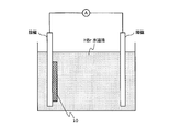
- FIG. 2A and FIG. 2B are schematic diagrams for explaining a method for measuring the content of tin oxide (tin oxide amount) in the oxide film layer.
- tin oxide amount tin oxide amount
- an electrolytic treatment bath is prepared in which a hydrobromic acid aqueous solution (HBr aqueous solution) having the above concentration from which dissolved oxygen is removed is retained.
- An anode and a cathode provided with a measurement sample that is, the steel plate for containers 10) are installed in the electrolytic treatment bath.
- the materials of the anode and the cathode are not particularly limited.
- platinum electrodes can be used as the anode and the cathode. It is also possible to use the test piece itself as a cathode.
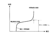
- FIG. 2B schematically shows the obtained measurement chart.
- each of the tangent line on the potential axis side and the tangent line on the time axis side is specified, and the position of the intersection of the tangent lines is specified.
- the length of the perpendicular drawn from this intersection to the potential axis is the chart length L (unit: mm).
- the tin oxide amount Q can be calculated by the following equation 101.
- I is the current density (unit: mA)
- S is the area of the sample (unit: cm 2 )
- T completely removes the oxide film layer 107 ( That is, the time required for completely reducing the oxide film layer 107 (unit: sec).
- the time T required to completely remove the oxide film layer 107 includes the full scale length LFS , the full scale chart feed rate TFS, and the chart length L obtained from the measurement chart. Utilizing this, it can be calculated by the following equation 102. Therefore, the tin oxide amount Q can be calculated by using the following formula 101 and formula 102.
- the amount of metal Zr and the amount of P in the chemical conversion coating layer 109 can be measured by a quantitative analysis method such as fluorescent X-ray analysis, for example.
- the measuring method of each component amount as described above is not limited to the above method, and other known measuring methods can be applied.
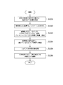
- FIG. 3A is a flowchart for explaining an example of a flow of an evaluation method for resistance to sulfurization blackening.
- FIG. 3B is an explanatory diagram for explaining an evaluation method for resistance to sulfurization blackening.
- a gold-colored paint (Valsper, 28S93MB) is attached to the surface of a sample and baked to form a coating film (step S101).
- a gold-colored paint (Valsper, 28S93MB) is attached to the surface of a sample and baked to form a coating film (step S101).
- the steel plate for containers which formed the base Ni layer, Sn plating layer, the oxide film layer, and the chemical conversion treatment film layer on the steel plate surface by said method is used.
- a 0.6 mass% L-cysteine solution boiled for 1 hour is sealed in a heat-resistant bottle 201 (manufactured by SCHOTT, 100 mL heat-resistant bottle, 017260-100A) (step S102).
- the O-ring 202, the packing silicon rubber 203, the sample 204 (42 ⁇ ) created in step S201, and the packing silicon rubber 205 are placed and fixed in this order in the mouth of the heat-resistant bottle (step S103).
- a lid 206 (GL45, inner diameter 45 ⁇ , outer diameter 55 ⁇ , manufactured by Shibata Chemical Co., Ltd.) is placed on the heat-resistant bottle, and placed in a soaking furnace so that the lid is on the bottom (step S104).
- the heat-resistant bottle is heat-treated at 110 ° C. for 30 minutes (step S105).
- the heat-resistant bottle is taken out from the soaking furnace, and the degree of blackening at the contact portion between the sample and the L-cysteine liquid is observed with the naked eye (step S106).
- Steps S102 to S105 are common to the evaluation method of sulfur blackening resistance by the naked eye and the evaluation method of sulfur blackening resistance by YI.
- the yellowness of the sample after the reaction with the L-cysteine solution is measured with a spectrocolorimeter in the above step S106.
- a spectrocolorimeter conforming to JIS Z-8722 condition c may be used, and the measurement method is SCI (including specularly reflected light) measurement which is not easily affected by surface properties.
- SCI including specularly reflected light
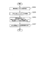
- FIG. 4 is a flowchart for explaining an example of the flow of the manufacturing method of the steel plate for containers in the present embodiment.
- the base Ni layer 103 is formed by performing Ni plating or Fe—Ni alloy plating on the steel plate 101 (step S201).
- step S203 Sn plating is performed on the steel plate 101 on which the base Ni layer 103 is formed. Thereafter, the oxide film layer 107 is formed by surface oxidation while forming the Sn plating layer 105 containing island-like Sn by molten tin treatment (reflow treatment) (step S205).
- a chemical conversion treatment film layer 109 is formed on the oxide film layer 107 by electrolytic treatment (step S207).
- the processing is performed in such a flow, whereby the container steel plate 10 in the present embodiment is manufactured.
- the manufacturing method of the steel plate for containers and the steel plate for containers in the present invention will be specifically described with reference to Examples and Comparative Examples.
- the Example shown below is only an example of the manufacturing method of the steel plate for containers and the steel plate for containers in this invention, Comprising: The manufacturing method of the steel plate for containers in this invention and a steel plate for containers is limited to the Example shown below. Is not to be done.
- Example 2 A steel plate generally used as a steel plate for containers was used, and Ni plating and Sn plating were sequentially applied to the steel plate by a known method. Subsequently, a molten tin treatment was performed under the conditions shown in Table 1 below to form a Sn plating layer and an oxide film layer, and then a chemical conversion treatment film layer was formed under the conditions shown in Table 1 below.
- the amount of metallic Ni in the formed underlying Ni layer and the amount of metallic Sn in the Sn plating layer were measured by the fluorescent X-ray method and are shown in Table 2 below.
- the amount of tin oxide in the oxide film layer was measured by the method described with reference to FIGS. 2A and 2B and is shown in Table 2 below.
- the amount of each component in the chemical conversion coating layer was measured by fluorescent X-ray analysis and is shown in Table 2 below.
- the resistance to blackening resistance of each level of the sample was evaluated with the naked eye by the method described with reference to FIGS. 3A and 3B.
- the appearance of the contact portion in contact with the heat-resistant bottle was observed, and a score of 1 to 10 was assigned according to the ratio (area ratio) of the portion where the blackening occurred in the contact portion.
- the score is 8 points or more (that is, when blackening does not occur in 50% or more of the contact portion), excellent resistance to sulfur blackening as a steel plate for containers is exhibited.
- the area of the blackened portion is less than 10% 9 points: the area of the blackened portion is 10% or more and less than 30% 8 points: the area of the blackened portion is 30% or more, Less than 50% 7 points: The area of the blackened portion is 50% or more and less than 60% 6 points: The area of the blackened portion is 60% or more and less than 65% 5 points: The blackened portion Area of 65% or more and less than 75% 4 points: Area of blackened portion is 75% or more and less than 85% 3 point: Area of blackened portion is 85% or more and less than 90% 2 points : Area of blackened portion is 90% or more and less than 95% 1 point: Area of blackened portion is 95% or more
- each experimental example shown in Table 1 and Table 2 is an experiment mainly focusing on each condition at the time of manufacturing the steel plate for containers, and each experimental example shown in Table 3 and Table 4 Conducts experiments focusing on the characteristics of the manufactured steel plates for containers.
- Each experimental example shown in Table 5 and Table 6 is an experiment in which the adhesion amount of tin oxide is changed by changing the molten tin treatment time. As is apparent from Tables 1 to 6, the above-described evaluation test for sulfurization blackening revealed that the steel sheet of the present invention had excellent resistance to blackening.
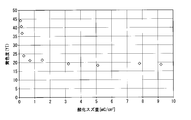
- YI As apparent from Table 8 and FIGS. 5A and 5B, the numerical value of YI corresponds well with the sensory evaluation result by the naked eye, and YI is used to quantitatively indicate the color change of the surface due to the blackening of sulfide. It was found that it can be applied as an indicator.
- the present invention by forming an oxide film layer between the chemical conversion treatment film layer and the Sn plating layer, it is possible to realize sulfurization blackening resistance and cost reduction using the chemical conversion treatment film. Become.
Landscapes
- Chemical & Material Sciences (AREA)
- Engineering & Computer Science (AREA)
- Chemical Kinetics & Catalysis (AREA)
- Materials Engineering (AREA)
- Metallurgy (AREA)
- Organic Chemistry (AREA)
- Electrochemistry (AREA)
- Inorganic Chemistry (AREA)
- Mechanical Engineering (AREA)
- Other Surface Treatments For Metallic Materials (AREA)
- Electroplating Methods And Accessories (AREA)
- Laminated Bodies (AREA)
Abstract
Priority Applications (7)
| Application Number | Priority Date | Filing Date | Title |
|---|---|---|---|
| ES14800433T ES2782973T3 (es) | 2013-05-21 | 2014-05-21 | Chapa de acero para recipientes y método para producir una chapa de acero para recipientes |
| JP2015518277A JP6070836B2 (ja) | 2013-05-21 | 2014-05-21 | 容器用鋼板及び容器用鋼板の製造方法 |
| KR1020157032927A KR101734747B1 (ko) | 2013-05-21 | 2014-05-21 | 용기용 강판 및 용기용 강판의 제조 방법 |
| CN201480028919.XA CN105283584B (zh) | 2013-05-21 | 2014-05-21 | 容器用钢板以及容器用钢板的制造方法 |
| MYPI2015704152A MY182935A (en) | 2013-05-21 | 2014-05-21 | Steel sheet for containers, and method for producing steel sheet for containers |
| US14/891,945 US10443141B2 (en) | 2013-05-21 | 2014-05-21 | Steel sheet for containers, and method for producing steel sheet for containers |
| EP14800433.6A EP3000917B1 (fr) | 2013-05-21 | 2014-05-21 | Tôles destinées à des contenants et leur procédé de production |
Applications Claiming Priority (2)
| Application Number | Priority Date | Filing Date | Title |
|---|---|---|---|
| JP2013107304 | 2013-05-21 | ||
| JP2013-107304 | 2013-05-21 |
Publications (1)
| Publication Number | Publication Date |
|---|---|
| WO2014189081A1 true WO2014189081A1 (fr) | 2014-11-27 |
Family
ID=51933633
Family Applications (1)
| Application Number | Title | Priority Date | Filing Date |
|---|---|---|---|
| PCT/JP2014/063478 Ceased WO2014189081A1 (fr) | 2013-05-21 | 2014-05-21 | Tôles destinées à des contenants et leur procédé de production |
Country Status (9)
| Country | Link |
|---|---|
| US (1) | US10443141B2 (fr) |
| EP (1) | EP3000917B1 (fr) |
| JP (1) | JP6070836B2 (fr) |
| KR (1) | KR101734747B1 (fr) |
| CN (1) | CN105283584B (fr) |
| ES (1) | ES2782973T3 (fr) |
| MY (1) | MY182935A (fr) |
| TW (1) | TWI549812B (fr) |
| WO (1) | WO2014189081A1 (fr) |
Cited By (10)
| Publication number | Priority date | Publication date | Assignee | Title |
|---|---|---|---|---|
| JP6066030B2 (ja) * | 2015-01-09 | 2017-01-25 | 新日鐵住金株式会社 | 容器用鋼板及び容器用鋼板の製造方法 |
| WO2017163298A1 (fr) * | 2016-03-22 | 2017-09-28 | 新日鐵住金株式会社 | Plaque d'acier traitée par conversion chimique et procédé de production d'une plaque d'acier traitée par conversion chimique |
| KR20180019188A (ko) * | 2015-06-23 | 2018-02-23 | 신닛테츠스미킨 카부시키카이샤 | 용기용 강판 및 용기용 강판의 제조 방법 |
| JPWO2016207967A1 (ja) * | 2015-06-23 | 2018-04-19 | 新日鐵住金株式会社 | 容器用鋼板及び容器用鋼板の製造方法 |
| EP3336942A4 (fr) * | 2015-08-12 | 2018-07-18 | JFE Steel Corporation | Plaque métallique pour séparateur de pile à combustible à électrolyte polymère et plaque métallique pour fabriquer celle-ci |
| EP3284850A4 (fr) * | 2015-04-16 | 2018-09-19 | Nippon Steel & Sumitomo Metal Corporation | Tôle d'acier pour conteneur et procédé de fabrication de tôle d'acier pour conteneur |
| US10431832B2 (en) | 2014-04-15 | 2019-10-01 | Jfe Steel Corporation | Stainless-steel foil for separator of polymer electrolyte fuel cell |
| US10563311B2 (en) | 2015-04-16 | 2020-02-18 | Nippon Steel Corporation | Steel sheet for container and method for producing steel sheet for container |
| WO2021192614A1 (fr) * | 2020-03-26 | 2021-09-30 | 日本製鉄株式会社 | TÔLE D'ACIER PLAQUÉE À BASE DE Sn |
| JP7741460B1 (ja) * | 2025-03-18 | 2025-09-18 | 日本製鉄株式会社 | 電池ケース |
Families Citing this family (5)
| Publication number | Priority date | Publication date | Assignee | Title |
|---|---|---|---|---|
| JP6583539B2 (ja) * | 2016-03-22 | 2019-10-02 | 日本製鉄株式会社 | 化成処理鋼板及び化成処理鋼板の製造方法 |
| TWI633210B (zh) * | 2016-05-24 | 2018-08-21 | 新日鐵住金股份有限公司 | Sn系合金鍍敷鋼板 |
| CN109072449B (zh) * | 2016-06-24 | 2023-07-14 | 杰富意钢铁株式会社 | 电池外筒罐用钢板、电池外筒罐和电池 |
| KR102339193B1 (ko) * | 2017-07-28 | 2021-12-13 | 제이에프이 스틸 가부시키가이샤 | 전지 외통캔용 강판, 전지 외통캔 및 전지 |
| ES3030348T3 (en) * | 2018-03-01 | 2025-06-27 | Nippon Steel Corp | Sn-plated steel sheet and method for manufacturing sn-plated steel sheet |
Citations (5)
| Publication number | Priority date | Publication date | Assignee | Title |
|---|---|---|---|---|
| JP2007284789A (ja) | 2006-03-24 | 2007-11-01 | Nippon Steel Corp | 製缶加工性に優れた容器用鋼板 |
| JP2010261068A (ja) * | 2009-04-30 | 2010-11-18 | Jfe Steel Corp | 錫めっき鋼板およびその製造方法 |
| WO2011118588A1 (fr) * | 2010-03-23 | 2011-09-29 | 新日本製鐵株式会社 | Tôle d'acier pour conteneurs et procédé de fabrication de cette dernière |
| WO2012002360A1 (fr) * | 2010-06-29 | 2012-01-05 | 新日本製鐵株式会社 | Tôle d'acier pour contenant et son procédé de fabrication |
| JP2012062521A (ja) * | 2010-09-15 | 2012-03-29 | Jfe Steel Corp | 容器用鋼板の製造方法 |
Family Cites Families (6)
| Publication number | Priority date | Publication date | Assignee | Title |
|---|---|---|---|---|
| TWI391530B (zh) * | 2007-04-04 | 2013-04-01 | Nippon Steel Corp | A plated steel sheet for use in a tank and a method for manufacturing the same |
| CN101952479B (zh) * | 2008-02-18 | 2013-06-19 | 新日铁住金株式会社 | 罐用镀覆钢板及其制造方法 |
| JP5304000B2 (ja) * | 2008-04-07 | 2013-10-02 | 新日鐵住金株式会社 | 溶接性、外観、製缶加工密着性に優れた容器用鋼板 |
| CN103097582B (zh) * | 2010-09-15 | 2015-11-25 | 杰富意钢铁株式会社 | 容器用钢板及其制造方法 |
| JP5760355B2 (ja) * | 2010-09-15 | 2015-08-12 | Jfeスチール株式会社 | 容器用鋼板 |
| US9127341B2 (en) * | 2011-01-18 | 2015-09-08 | Nippon Steel & Sumitomo Metal Corporation | Steel sheet for container having excellent organic film performance and process for producing the same |
-
2014
- 2014-05-21 WO PCT/JP2014/063478 patent/WO2014189081A1/fr not_active Ceased
- 2014-05-21 KR KR1020157032927A patent/KR101734747B1/ko active Active
- 2014-05-21 MY MYPI2015704152A patent/MY182935A/en unknown
- 2014-05-21 CN CN201480028919.XA patent/CN105283584B/zh active Active
- 2014-05-21 ES ES14800433T patent/ES2782973T3/es active Active
- 2014-05-21 EP EP14800433.6A patent/EP3000917B1/fr active Active
- 2014-05-21 US US14/891,945 patent/US10443141B2/en active Active
- 2014-05-21 JP JP2015518277A patent/JP6070836B2/ja active Active
- 2014-05-21 TW TW103117763A patent/TWI549812B/zh active
Patent Citations (5)
| Publication number | Priority date | Publication date | Assignee | Title |
|---|---|---|---|---|
| JP2007284789A (ja) | 2006-03-24 | 2007-11-01 | Nippon Steel Corp | 製缶加工性に優れた容器用鋼板 |
| JP2010261068A (ja) * | 2009-04-30 | 2010-11-18 | Jfe Steel Corp | 錫めっき鋼板およびその製造方法 |
| WO2011118588A1 (fr) * | 2010-03-23 | 2011-09-29 | 新日本製鐵株式会社 | Tôle d'acier pour conteneurs et procédé de fabrication de cette dernière |
| WO2012002360A1 (fr) * | 2010-06-29 | 2012-01-05 | 新日本製鐵株式会社 | Tôle d'acier pour contenant et son procédé de fabrication |
| JP2012062521A (ja) * | 2010-09-15 | 2012-03-29 | Jfe Steel Corp | 容器用鋼板の製造方法 |
Cited By (22)
| Publication number | Priority date | Publication date | Assignee | Title |
|---|---|---|---|---|
| US10431832B2 (en) | 2014-04-15 | 2019-10-01 | Jfe Steel Corporation | Stainless-steel foil for separator of polymer electrolyte fuel cell |
| JP6066030B2 (ja) * | 2015-01-09 | 2017-01-25 | 新日鐵住金株式会社 | 容器用鋼板及び容器用鋼板の製造方法 |
| EP3284850A4 (fr) * | 2015-04-16 | 2018-09-19 | Nippon Steel & Sumitomo Metal Corporation | Tôle d'acier pour conteneur et procédé de fabrication de tôle d'acier pour conteneur |
| US10577705B2 (en) | 2015-04-16 | 2020-03-03 | Nippon Steel Corporation | Steel sheet for container and method for producing steel sheet for container |
| US10563311B2 (en) | 2015-04-16 | 2020-02-18 | Nippon Steel Corporation | Steel sheet for container and method for producing steel sheet for container |
| US10851467B2 (en) | 2015-06-23 | 2020-12-01 | Nippon Steel Corporation | Steel sheet for containers, and method for producing steel sheet for containers |
| KR102087669B1 (ko) * | 2015-06-23 | 2020-03-11 | 닛폰세이테츠 가부시키가이샤 | 용기용 강판 및 용기용 강판의 제조 방법 |
| KR20180019188A (ko) * | 2015-06-23 | 2018-02-23 | 신닛테츠스미킨 카부시키카이샤 | 용기용 강판 및 용기용 강판의 제조 방법 |
| EP3315636A4 (fr) * | 2015-06-23 | 2019-02-13 | Nippon Steel & Sumitomo Metal Corporation | Tôle d'acier pour contenant et son procédé de production |
| JPWO2016207966A1 (ja) * | 2015-06-23 | 2018-04-26 | 新日鐵住金株式会社 | 容器用鋼板及び容器用鋼板の製造方法 |
| US10465309B2 (en) | 2015-06-23 | 2019-11-05 | Nippon Steel Corporation | Steel sheet for containers, and method for producing steel sheet for containers |
| JPWO2016207967A1 (ja) * | 2015-06-23 | 2018-04-19 | 新日鐵住金株式会社 | 容器用鋼板及び容器用鋼板の製造方法 |
| US10516174B2 (en) | 2015-08-12 | 2019-12-24 | Jfe Steel Corporation | Metal sheet for separators of polymer electrolyte fuel cells, and metal sheet for manufacturing the same |
| EP3336942A4 (fr) * | 2015-08-12 | 2018-07-18 | JFE Steel Corporation | Plaque métallique pour séparateur de pile à combustible à électrolyte polymère et plaque métallique pour fabriquer celle-ci |
| JPWO2017163298A1 (ja) * | 2016-03-22 | 2019-01-31 | 新日鐵住金株式会社 | 化成処理鋼板及び化成処理鋼板の製造方法 |
| WO2017163298A1 (fr) * | 2016-03-22 | 2017-09-28 | 新日鐵住金株式会社 | Plaque d'acier traitée par conversion chimique et procédé de production d'une plaque d'acier traitée par conversion chimique |
| WO2021192614A1 (fr) * | 2020-03-26 | 2021-09-30 | 日本製鉄株式会社 | TÔLE D'ACIER PLAQUÉE À BASE DE Sn |
| JPWO2021192614A1 (fr) * | 2020-03-26 | 2021-09-30 | ||
| CN115315541A (zh) * | 2020-03-26 | 2022-11-08 | 日本制铁株式会社 | Sn系镀覆钢板 |
| JP7295486B2 (ja) | 2020-03-26 | 2023-06-21 | 日本製鉄株式会社 | Sn系めっき鋼板 |
| CN115315541B (zh) * | 2020-03-26 | 2023-10-24 | 日本制铁株式会社 | Sn系镀覆钢板 |
| JP7741460B1 (ja) * | 2025-03-18 | 2025-09-18 | 日本製鉄株式会社 | 電池ケース |
Also Published As
| Publication number | Publication date |
|---|---|
| CN105283584B (zh) | 2017-09-05 |
| EP3000917A4 (fr) | 2017-01-18 |
| EP3000917A1 (fr) | 2016-03-30 |
| EP3000917B1 (fr) | 2020-03-11 |
| JPWO2014189081A1 (ja) | 2017-02-23 |
| US20160122891A1 (en) | 2016-05-05 |
| JP6070836B2 (ja) | 2017-02-01 |
| KR101734747B1 (ko) | 2017-05-11 |
| TWI549812B (zh) | 2016-09-21 |
| KR20150143828A (ko) | 2015-12-23 |
| ES2782973T3 (es) | 2020-09-16 |
| TW201504034A (zh) | 2015-02-01 |
| US10443141B2 (en) | 2019-10-15 |
| CN105283584A (zh) | 2016-01-27 |
| MY182935A (en) | 2021-02-05 |
Similar Documents
| Publication | Publication Date | Title |
|---|---|---|
| JP6070836B2 (ja) | 容器用鋼板及び容器用鋼板の製造方法 | |
| JP6128280B2 (ja) | 酸性内容物貯蔵容器用化成処理鋼板及び酸性内容物貯蔵容器用化成処理鋼板の製造方法 | |
| JP6103139B2 (ja) | 化成処理鋼板及び化成処理鋼板の製造方法 | |
| JPWO2018190412A1 (ja) | Snめっき鋼板及びSnめっき鋼板の製造方法 | |
| JP6119930B2 (ja) | 容器用鋼板及び容器用鋼板の製造方法 | |
| JP5994960B1 (ja) | 容器用鋼板及び容器用鋼板の製造方法 | |
| JP6066030B2 (ja) | 容器用鋼板及び容器用鋼板の製造方法 | |
| JP6583538B2 (ja) | 化成処理鋼板及び化成処理鋼板の製造方法 | |
| JP6583539B2 (ja) | 化成処理鋼板及び化成処理鋼板の製造方法 | |
| JP6468059B2 (ja) | Snめっき鋼板及びSnめっき鋼板の製造方法 | |
| JP6565308B2 (ja) | 容器用鋼板及び容器用鋼板の製造方法 |
Legal Events
| Date | Code | Title | Description |
|---|---|---|---|
| WWE | Wipo information: entry into national phase |
Ref document number: 201480028919.X Country of ref document: CN |
|
| 121 | Ep: the epo has been informed by wipo that ep was designated in this application |
Ref document number: 14800433 Country of ref document: EP Kind code of ref document: A1 |
|
| ENP | Entry into the national phase |
Ref document number: 2015518277 Country of ref document: JP Kind code of ref document: A |
|
| WWE | Wipo information: entry into national phase |
Ref document number: 14891945 Country of ref document: US |
|
| ENP | Entry into the national phase |
Ref document number: 20157032927 Country of ref document: KR Kind code of ref document: A |
|
| NENP | Non-entry into the national phase |
Ref country code: DE |
|
| WWE | Wipo information: entry into national phase |
Ref document number: 2014800433 Country of ref document: EP |