WO2014189092A1 - ダブルジェット式フイルム冷却構造とその製造方法 - Google Patents
ダブルジェット式フイルム冷却構造とその製造方法 Download PDFInfo
- Publication number
- WO2014189092A1 WO2014189092A1 PCT/JP2014/063517 JP2014063517W WO2014189092A1 WO 2014189092 A1 WO2014189092 A1 WO 2014189092A1 JP 2014063517 W JP2014063517 W JP 2014063517W WO 2014189092 A1 WO2014189092 A1 WO 2014189092A1
- Authority
- WO
- WIPO (PCT)
- Prior art keywords
- passage
- wall surface
- branch
- main passage
- cooling structure
- Prior art date
- Legal status (The legal status is an assumption and is not a legal conclusion. Google has not performed a legal analysis and makes no representation as to the accuracy of the status listed.)
- Ceased
Links
Images


Classifications
-
- F—MECHANICAL ENGINEERING; LIGHTING; HEATING; WEAPONS; BLASTING
- F01—MACHINES OR ENGINES IN GENERAL; ENGINE PLANTS IN GENERAL; STEAM ENGINES
- F01D—NON-POSITIVE DISPLACEMENT MACHINES OR ENGINES, e.g. STEAM TURBINES
- F01D5/00—Blades; Blade-carrying members; Heating, heat-insulating, cooling or antivibration means on the blades or the members
- F01D5/12—Blades
- F01D5/14—Form or construction
- F01D5/18—Hollow blades, i.e. blades with cooling or heating channels or cavities; Heating, heat-insulating or cooling means on blades
- F01D5/186—Film cooling
-
- B—PERFORMING OPERATIONS; TRANSPORTING
- B23—MACHINE TOOLS; METAL-WORKING NOT OTHERWISE PROVIDED FOR
- B23H—WORKING OF METAL BY THE ACTION OF A HIGH CONCENTRATION OF ELECTRIC CURRENT ON A WORKPIECE USING AN ELECTRODE WHICH TAKES THE PLACE OF A TOOL; SUCH WORKING COMBINED WITH OTHER FORMS OF WORKING OF METAL
- B23H1/00—Electrical discharge machining, i.e. removing metal with a series of rapidly recurring electrical discharges between an electrode and a workpiece in the presence of a fluid dielectric
- B23H1/04—Electrodes specially adapted therefor or their manufacture
-
- B—PERFORMING OPERATIONS; TRANSPORTING
- B23—MACHINE TOOLS; METAL-WORKING NOT OTHERWISE PROVIDED FOR
- B23H—WORKING OF METAL BY THE ACTION OF A HIGH CONCENTRATION OF ELECTRIC CURRENT ON A WORKPIECE USING AN ELECTRODE WHICH TAKES THE PLACE OF A TOOL; SUCH WORKING COMBINED WITH OTHER FORMS OF WORKING OF METAL
- B23H9/00—Machining specially adapted for treating particular metal objects or for obtaining special effects or results on metal objects
- B23H9/10—Working turbine blades or nozzles
-
- B—PERFORMING OPERATIONS; TRANSPORTING
- B23—MACHINE TOOLS; METAL-WORKING NOT OTHERWISE PROVIDED FOR
- B23H—WORKING OF METAL BY THE ACTION OF A HIGH CONCENTRATION OF ELECTRIC CURRENT ON A WORKPIECE USING AN ELECTRODE WHICH TAKES THE PLACE OF A TOOL; SUCH WORKING COMBINED WITH OTHER FORMS OF WORKING OF METAL
- B23H9/00—Machining specially adapted for treating particular metal objects or for obtaining special effects or results on metal objects
- B23H9/14—Making holes
-
- F—MECHANICAL ENGINEERING; LIGHTING; HEATING; WEAPONS; BLASTING
- F01—MACHINES OR ENGINES IN GENERAL; ENGINE PLANTS IN GENERAL; STEAM ENGINES
- F01D—NON-POSITIVE DISPLACEMENT MACHINES OR ENGINES, e.g. STEAM TURBINES
- F01D9/00—Stators
- F01D9/06—Fluid supply conduits to nozzles or the like
- F01D9/065—Fluid supply or removal conduits traversing the working fluid flow, e.g. for lubrication-, cooling-, or sealing fluids
-
- F—MECHANICAL ENGINEERING; LIGHTING; HEATING; WEAPONS; BLASTING
- F23—COMBUSTION APPARATUS; COMBUSTION PROCESSES
- F23R—GENERATING COMBUSTION PRODUCTS OF HIGH PRESSURE OR HIGH VELOCITY, e.g. GAS-TURBINE COMBUSTION CHAMBERS
- F23R3/00—Continuous combustion chambers using liquid or gaseous fuel
- F23R3/02—Continuous combustion chambers using liquid or gaseous fuel characterised by the air-flow or gas-flow configuration
- F23R3/04—Air inlet arrangements
- F23R3/06—Arrangement of apertures along the flame tube
-
- F—MECHANICAL ENGINEERING; LIGHTING; HEATING; WEAPONS; BLASTING
- F05—INDEXING SCHEMES RELATING TO ENGINES OR PUMPS IN VARIOUS SUBCLASSES OF CLASSES F01-F04
- F05D—INDEXING SCHEME FOR ASPECTS RELATING TO NON-POSITIVE-DISPLACEMENT MACHINES OR ENGINES, GAS-TURBINES OR JET-PROPULSION PLANTS
- F05D2230/00—Manufacture
- F05D2230/10—Manufacture by removing material
- F05D2230/12—Manufacture by removing material by spark erosion methods
-
- F—MECHANICAL ENGINEERING; LIGHTING; HEATING; WEAPONS; BLASTING
- F05—INDEXING SCHEMES RELATING TO ENGINES OR PUMPS IN VARIOUS SUBCLASSES OF CLASSES F01-F04
- F05D—INDEXING SCHEME FOR ASPECTS RELATING TO NON-POSITIVE-DISPLACEMENT MACHINES OR ENGINES, GAS-TURBINES OR JET-PROPULSION PLANTS
- F05D2240/00—Components
- F05D2240/10—Stators
- F05D2240/11—Shroud seal segments
-
- F—MECHANICAL ENGINEERING; LIGHTING; HEATING; WEAPONS; BLASTING
- F05—INDEXING SCHEMES RELATING TO ENGINES OR PUMPS IN VARIOUS SUBCLASSES OF CLASSES F01-F04
- F05D—INDEXING SCHEME FOR ASPECTS RELATING TO NON-POSITIVE-DISPLACEMENT MACHINES OR ENGINES, GAS-TURBINES OR JET-PROPULSION PLANTS
- F05D2240/00—Components
- F05D2240/80—Platforms for stationary or moving blades
- F05D2240/81—Cooled platforms
-
- F—MECHANICAL ENGINEERING; LIGHTING; HEATING; WEAPONS; BLASTING
- F05—INDEXING SCHEMES RELATING TO ENGINES OR PUMPS IN VARIOUS SUBCLASSES OF CLASSES F01-F04
- F05D—INDEXING SCHEME FOR ASPECTS RELATING TO NON-POSITIVE-DISPLACEMENT MACHINES OR ENGINES, GAS-TURBINES OR JET-PROPULSION PLANTS
- F05D2250/00—Geometry
- F05D2250/10—Two-dimensional
- F05D2250/14—Two-dimensional elliptical
-
- F—MECHANICAL ENGINEERING; LIGHTING; HEATING; WEAPONS; BLASTING
- F05—INDEXING SCHEMES RELATING TO ENGINES OR PUMPS IN VARIOUS SUBCLASSES OF CLASSES F01-F04
- F05D—INDEXING SCHEME FOR ASPECTS RELATING TO NON-POSITIVE-DISPLACEMENT MACHINES OR ENGINES, GAS-TURBINES OR JET-PROPULSION PLANTS
- F05D2250/00—Geometry
- F05D2250/20—Three-dimensional
- F05D2250/23—Three-dimensional prismatic
- F05D2250/231—Three-dimensional prismatic cylindrical
-
- F—MECHANICAL ENGINEERING; LIGHTING; HEATING; WEAPONS; BLASTING
- F05—INDEXING SCHEMES RELATING TO ENGINES OR PUMPS IN VARIOUS SUBCLASSES OF CLASSES F01-F04
- F05D—INDEXING SCHEME FOR ASPECTS RELATING TO NON-POSITIVE-DISPLACEMENT MACHINES OR ENGINES, GAS-TURBINES OR JET-PROPULSION PLANTS
- F05D2250/00—Geometry
- F05D2250/70—Shape
- F05D2250/75—Shape given by its similarity to a letter, e.g. T-shaped
-
- F—MECHANICAL ENGINEERING; LIGHTING; HEATING; WEAPONS; BLASTING
- F05—INDEXING SCHEMES RELATING TO ENGINES OR PUMPS IN VARIOUS SUBCLASSES OF CLASSES F01-F04
- F05D—INDEXING SCHEME FOR ASPECTS RELATING TO NON-POSITIVE-DISPLACEMENT MACHINES OR ENGINES, GAS-TURBINES OR JET-PROPULSION PLANTS
- F05D2260/00—Function
- F05D2260/20—Heat transfer, e.g. cooling
- F05D2260/202—Heat transfer, e.g. cooling by film cooling
-
- F—MECHANICAL ENGINEERING; LIGHTING; HEATING; WEAPONS; BLASTING
- F23—COMBUSTION APPARATUS; COMBUSTION PROCESSES
- F23R—GENERATING COMBUSTION PRODUCTS OF HIGH PRESSURE OR HIGH VELOCITY, e.g. GAS-TURBINE COMBUSTION CHAMBERS
- F23R2900/00—Special features of, or arrangements for continuous combustion chambers; Combustion processes therefor
- F23R2900/03042—Film cooled combustion chamber walls or domes
Definitions
- the present invention provides a jet opening on a wall surface facing a hot gas passage such as a moving blade, a stationary blade, and an inner cylinder of a combustor in a gas turbine engine, and a cooling medium jetted from the jet opening along the wall surface.
- the present invention relates to a film cooling structure for cooling a wall surface by flowing.
- a wall surface such as a moving blade in a gas turbine engine (hereinafter simply referred to as “gas turbine”) has been provided with a number of ejection openings directed in the same direction, such as air ejected from these ejection openings.
- the wall surface exposed to the high temperature gas is cooled by the film flow of the cooling medium.
- a circular hole is provided in the wall so as to be inclined toward the downstream side of the high-temperature gas, and the cooling medium is ejected from an elliptical ejection port opened in the wall surface.
- an improved cooling structure having, for example, a structure in which the jet outlet to the wall surface of the cooling medium has a double leaf piece shape (Patent Document 1) and a pair of jet outlets Some have a distribution unit (Patent Document 2).
- JP 2008-8288 A Japanese Patent No. 4954309
- the cooling effect can be enhanced by expanding the width of the cooling medium along the wall surface. This is presumably because the film efficiency indicating the cooling efficiency on the wall surface is increased.
- Tg is the temperature of the high temperature gas
- Tf is the surface temperature of the wall surface
- Tc is the temperature of the cooling medium on the wall surface.
- the shape of the central portion of the jet outlet is not a simple ellipse but a curved line having a plurality of radii of curvature (paragraphs 0016-0017), the number of manufacturing steps increases.
- the said patent document 2 although peeling from the wall surface of a cooling medium can be suppressed and film efficiency can be improved, since the said distribution part becomes undercut seeing from a wall surface side, a
- the present invention provides a film cooling structure that can efficiently cool wall surfaces such as gas turbine movements and stationary blades while suppressing the separation of the cooling medium film from the wall surfaces.
- the purpose is to do.
- a double jet film cooling structure comprises: The wall facing the hot gas passage is provided with an ejection opening for ejecting the cooling medium toward the downstream side of the passage, A main passage composed of a straight circular hole for supplying the cooling medium to the ejection opening, and a pair of branch passages composed of a straight circular hole branching from a branch point on the main passage and having the ejection opening as an outlet; A communication passage that communicates the main passage and the branch passage and has the ejection opening as an outlet is formed in the wall, The ejection direction of the cooling medium ejected from the pair of branch passages is set to be inclined with respect to the flow direction of the high-temperature gas so as to form a vortex in a direction in which the cooling medium is pressed against the wall surface.
- the cross sections of the main passage and the branch passage have the same constant inner diameter
- the communication path has an envelope surface that connects a group of straight circular holes having the constant inner diameter through the branch point,
- a lateral ejection angle ⁇ along the wall surface with respect to the flow direction of the high-temperature gas in each ejection direction from the pair of branch passages is set so as to face opposite directions across the flow direction,
- a main longitudinal angle ⁇ 1 formed by the axial direction of the main passage and the wall surface is set to be larger than a branch vertical angle ⁇ 2 formed by the axial direction of the branch passage and the wall surface.
- the lateral ejection angles along the wall surface with respect to the flow direction of the high-temperature gas in the respective ejection directions of the cooling medium from the pair of ejection holes are opposite to each other across the flow direction. Since it is set to face, a wide film flow of the cooling medium is effectively formed on the wall surface along the flow direction of the hot gas, and the film efficiency is improved.
- the main longitudinal angle ⁇ 1 formed by the axial direction of the main passage and the wall surface is set to be larger than the branch vertical angle ⁇ 2 formed by the axial direction of the branch passage and the wall surface.
- the cooling medium ejected is separated by the cooling medium ejected from the main passage to form a pair of straight flow with high directivity. Since a low pressure part with sufficiently low pressure is generated between the pair of straight flow with high directivity, the vortex flow formed by the straight flow causes a strong flow toward the wall surface from around the straight flow to the low pressure part. It is formed. For this reason, it is suppressed that a cooling medium peels from a wall surface, the film efficiency on a wall surface is improved, and a wall surface is cooled effectively.
- the cross sections of the main passage and the branch passage have the same constant inner diameter
- the communication passage connecting the main passage and the branch passage is a straight circular hole that passes through the branch point and has the constant inner diameter. Since it has an envelope surface that connects groups, all of the main passage, branch passage and communication passage can be processed from the wall surface side by a single cylindrical processing tool, for example, a machining electrode for electric discharge machining. It becomes easy.
- the wall surface can be efficiently cooled by suppressing the separation of the cooling medium on the wall surface exposed to the high-temperature gas and generating a good film flow on the wall surface.
- a cooling structure can be easily formed.
- the angle difference ⁇ between the main longitudinal angle ⁇ 1 and the branching longitudinal angle ⁇ 2 is 3 to 15 °.
- the main passage is between the pair of branching passages. Therefore, the cooling medium ejected from the pair of branch passages is sufficiently separated from each other, and a low-pressure portion is reliably formed between the straight flow of the cooling medium. Strongly presses the flow against the wall to improve film efficiency.
- a rear surface portion of the envelope surface forming the communication path is flat.
- the “rear surface portion” refers to a surface located on the downstream side in the flow direction of the hot gas.
- a ratio Lc / H of a branch point height Lc to a height H in the orthogonal direction perpendicular to the wall surface of the main passage is 0.3 to 0.9.
- the cooling medium is smoothly branched from the main passage to the branch passage.
- the lateral ejection angle ⁇ from each branch passage is in the range of 10 to 45 °.
- the main longitudinal angle ⁇ 1 of the main passage is preferably 10 to 45 °, and the distance W along the wall surface between the outlets of the pair of branch passages is relative to the constant inner diameter D of the main passage. It is preferably set to 1.0 to 5.0D. According to these preferable configurations, a strong vortex flowing toward the wall surface is generated, and the wall surface can be cooled more effectively.
- the manufacturing method according to the present invention is a method of forming the double jet film cooling structure of the present invention by electric discharge machining, On the wall surface facing the passage of the high-temperature gas, the main passage having the constant inner diameter is formed by a cylindrical processing electrode having a predetermined outer diameter, A discharge passage is continuously formed from the communication passage to the branch passage by discharging the machining electrode while inclining the machining electrode with respect to the axis of the main passage. According to this method, all of the main passage, the branch passage, and the communication passage can be processed from the wall surface side by a single cylindrical processing electrode, so that manufacturing is facilitated.
- FIG. 1 is a plan view of a wall surface 1 to which a double jet film cooling structure according to an embodiment of the present invention is applied.
- the wall surface 1 is exposed to a high-temperature gas G flowing in the direction of the arrow, and an ejection opening 2 through which a cooling medium such as air is injected into the passage GP of the high-temperature gas G is provided in the wall surface 1
- a plurality are arranged side by side in a substantially orthogonal direction (vertical direction in FIG. 1).
- the upstream side along the flow direction of the hot gas G is referred to as the front side
- the downstream side is referred to as the rear side.
- each ejection opening 2 has a main passage 3 formed inside a wall 10 having a wall surface 1 as an upper surface, branch passages 4 and 5 branched from the main passage 3, and main passages 3.
- the passage 3 and the branch passages 4 and 5 are connected to communication passages 6 and 7 that communicate with each other. That is, the ejection opening 2 is formed by the outlets 3a, 4a, 5a, 6a, 7a of these passages 3-6.
- the main passage 3 is parallel to the flow direction of the hot gas G in a plan view as viewed from the direction orthogonal to the wall surface 1, and the branch passages 4 and 5 extend from the main passage 3 to the flow direction of the hot gas G.
- the communication passages 6 and 7 are configured so that the main passage 3 and the branch passages 4 and 5 are respectively transverse to the flow direction (vertical direction in FIG. 1). ).
- These passages 3 to 7 include the axis C3 of the main passage 3, have a plane-symmetric shape with respect to the orthogonal plane VP orthogonal to the wall surface 1, and are formed by, for example, electric discharge machining as will be described later.
- the branch passages 4 and 5 are branched from the same branch point P on the axis C3 of the main passage 3.
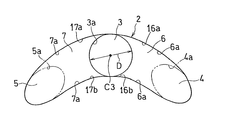
- the branch angle of the branch passages 4 and 5 viewed from the direction orthogonal to the wall surface 1, that is, the branch angle ⁇ shown in FIG. 2, is preferably 5 to 30 °, and more preferably 10 to 20 °.
- the jetting directions A and B of the cooling media CL4 and CL5 jetted from the branch passage outlets 4a and 5a do not coincide with the axial centers C4 and C5 of the branch passages 4 and 5, and as described below, the jet opening 2 It is influenced by the shape.
- the branch passages 4 and 5 are set so as to be directed in different directions on the surface along the wall surface 1, that is, in a plan view as viewed from a direction orthogonal to the wall surface 1.
- both the cooling media CL4 and CL5 passing through the branch passages 4 and 5 are ejected in directions away from each other.
- the ejection directions A and B are opposite to each other across the flow direction of the hot gas G in plan view, and along the wall surface 1 in the ejection directions A and B with respect to the flow direction of the hot gas G.
- the lateral injection angle ⁇ is set to be the same.
- the branch passage outlets 4a and 5a included in the ejection opening 2 have an elliptical shape with the axis C4 and C5 of the branch passages 4 and 5 as major axes.
- the lateral injection angle ⁇ is determined based on the front end 2f of the ejection opening 2, that is, the front end of the intersection 2f between the axis C3 of the main passage 3 and the front edge of the ejection opening 2 in the plan view of FIG. It is defined as an angle (an angle along the wall surface 1) formed by a straight line passing through 2f and the centers O1 and O2 of the branch passage outlets 4a and 5a and the axis C3.
- a portion CL3 of the cooling medium CL introduced into the main passage 3 flows into the passage downstream of the branch point P in the main passage 3 (hereinafter referred to as “main passage downstream portion”) 30, and the shaft 3 exits from the outlet 3a. It is ejected in the direction along the heart C3.
- Each of the main passage 3 and the branch passages 4 and 5 is formed by a straight circular hole having a constant inner diameter D.
- the communication paths 6 and 7 each include a straight path group passing through the branch point P, and are formed by an envelope surface connecting the path groups.
- Each passage forming the passage group has a constant inner diameter D which is the same as that of the main passage 3 and the branch passages 4 and 5 in cross section. Accordingly, as shown in FIG. 3 as viewed from the direction of the axis C3 of the main passage 3, the communication passage outlets 6a and 7a draw a smooth curve connecting the main passage outlet 3a and the branch passage outlets 4a and 5a.
- the circular holes forming the passages 3 to 7 are indicated by two-dot chain lines in the right column of FIG.
- the main passage 3 formed through the wall 10 opens to the inner surface 11 of the wall 10, and allows a cooling medium CL such as air to pass from the inside of the wall 10.
- An introduction opening 3 b for introduction into the main passage 3 is provided.
- the axis C3 of the main passage 3 is inclined toward the downstream side in the flow direction of the hot gas G from the introduction opening 3b toward the outlet 3a of the wall surface 1 which is the outer surface.
- the branch passages 4 and 5 have their axes C4 and C5 inclined toward the downstream side in the flow direction of the hot gas G from the branch point P toward the outlets 4a and 5a.
- the cooling media CL3 to CL5 are injected from the outlets 3a to 5a along the axes C3 to C5 of the main passage 3 and the branch passages 4 and 5 into the high temperature gas passage GP.
- Part of the cooling medium CL6, CL7 is also ejected from the outlets 6a, 7a of the communication passages 6, 7.
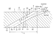
- the main longitudinal angle ⁇ 1 formed by the axis C3 and the wall surface 1 shown in FIG. 4 is larger than the branching vertical angle ⁇ 2 formed by the wall surfaces 1 by the shaft centers C4 and C5 of the branch passages 4 and 5.
- the branch longitudinal angles ⁇ 2 and ⁇ 2 of both branch passages 4 and 5 are the same.
- the axis C4 and C5 of the branch passages 4 and 5 are inclined in the horizontal direction (the direction of the front and back surfaces in FIG. 4) with respect to the vertical cross section in FIG. 4 does not appear correctly.
- This branching longitudinal direction angle ⁇ 2 is accurately shown in FIG. 5 which is a perspective view, and the virtual point P1 on the wall surface 1 directly above the branching point P and the centers O1 and O2 of the branch passage outlets 4a and 5a.
- the main passage outlet 3a and the branch passage outlets 4a and 5a included in the opening 2 are all elliptical. Further, since the main vertical direction angle ⁇ 1 is larger than the branch vertical direction angle ⁇ 2, the branch passage outlets 4a and 5a are located behind the main passage outlet 3a, that is, downstream of the hot gas G.
- the envelope surfaces 16 and 17 forming the communication passages 6 and 7 have smooth curved surfaces on the front surface portions 16a and 17a on the upstream side of the high temperature gas G, whereas the rear surface portions 16b and 17b are directed rearward. It is a flat surface with wide width. Therefore, each of the communication passage outlets 6a and 7a is a straight line having a width S. Since both the branch passages 4 and 5 are clearly separated in shape by the flat surfaces 16b and 17b, separation of the cooling media CL4 and CL5 ejected from the branch passages 4 and 5 is promoted.
- the cooling media CL4 and CL5 ejected from the branch passage outlets 4a and 5a of the ejection opening 2 affect each other and act so as to press the opponent against the wall surface 1. This will be described with reference to FIGS.
- a part of the cooling medium CL introduced into the main passage 3 flows into the branch passages 4 and 5.
- Most of the cooling medium flowing in the branch passages 4 and 5 becomes straight refrigerant flows F1 and F2 from the branch passage outlets 4a and 5a as branch passage components CL4 and CL5 with a lateral jet angle ⁇ . It is ejected into the gas passage GP.
- the rear ends 4aa and 5aa of the branch passage outlets 4a and 5a are located behind the rear end 3aa of the main passage outlet 3a, they are located behind the main passage outlet 3a in the branch passage outlets 4a and 5a.
- the straight refrigerant flows F1 and F2 ejected from the portion are formed as highly directional flows.
- most of the cooling medium CL flowing through the main passage downstream portion 30 out of the cooling medium CL that has passed through the main passage 3 is a straight passage directing in the direction along the axis C3 from the outlet 3a as the main passage component CL3.
- the main separated flow F3 is jetted into the high temperature gas passage GP.
- This separated flow F3 enters between the straight refrigerant flows F1 and F2 and has an action of separating the straight refrigerant flows F1 and F2.
- a part of the cooling mediums CL3 to CL5 flowing into the main passage downstream portion 30 and the branch passages 4 and 5 flows into the communication passages 6 and 7 and becomes sub-separated flows F4 and F5 from the outlets 6a and 7a. It is ejected into the gas passage GP and promotes separation of the straight refrigerant flows F1 and F2.
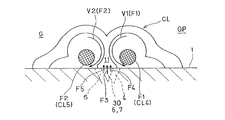
- FIG. 7 shows a cross section of the hot gas passage GP perpendicular to the flow direction of the hot gas G. Due to the main separation flow F3 and the sub-separation flows F4 and F5 from the main passage downstream portion 30 and the communication passages 6 and 7, the straight refrigerant flows F1 and F2 having high directivity from the branch passages 4 and 5 are parallel to the wall surface 1. As a result of the separation in the direction, a strong low pressure portion 11 is generated between the straight refrigerant flows F1 and F2. Thereby, the flow which goes to the wall surface 1 arises in the inner side part of each straight-ahead refrigerant
- the two branch passage outlets 4a and 5a in FIG. 6 are suitable for forming the vortex flows V1 and V2 by effectively generating the low-pressure part 11 and pressing the cooling medium C against the wall surface 1. It is necessary to dispose them by a distance.
- the branch passage outlets 4a and 5a at the ejection opening 2 facing the wall surface 1 have a substantially elliptical shape with the axes C4 and C5 of the branch passages 4 and 5 as major axes.
- the distance W along the wall surface 1 between the center points O1 and O2 of the pair of branch passage outlets 4a and 5a is preferably 1.0 to 5.0D with respect to the constant inner diameter D. More preferably, it is ⁇ 4.0D.
- the lateral ejection angle ⁇ between the ejection directions A and B from the branch passages 4 and 5 and the flow direction of the hot gas G is in the range of 10 to 45 °.
- the lateral ejection angle ⁇ is more preferably in the range of 20 to 40 °, and further preferably in the range of 25 to 35 °. If the lateral jet angle ⁇ is less than the above range, it is difficult to separate the vortex flows V1 and V2, and if it exceeds the above range, the straightness of the straight refrigerant flows F1 and F2 becomes insufficient, and the desired strength The eddy currents V1 and V2 cannot be obtained.
- the lateral injection angles ⁇ and ⁇ formed by the injection directions A and B from the branch passages 4 and 5 and the flow direction of the hot gas G may be different from each other.
- the ejection directions A and B from both the branch passages 4 and 5 are set symmetrically with respect to the axis C3 of the main passage 3.
- the lateral jet angle ⁇ with respect to the hot gas G is different between the branch passages 4 and 5.
- the main longitudinal direction angle ⁇ 1 formed between the axis C3 of the main passage 3 and the wall surface 1 shown in FIG. 4 is preferably in the range of 10 to 45 °, and more preferably in the range of 20 to 40 °.
- the branching longitudinal angle ⁇ 2 formed by the branch passages 4 and 5 and the wall surface 1 is preferably in the range of 5 to 40 °, and more preferably in the range of 10 to 35 °. If the main longitudinal direction angle ⁇ 1 and the branch injection angle ⁇ 2 are less than the above range, the vortex flows V1 and V2 in FIG. The vortex flows V1 and V2 having the desired strength cannot be obtained.
- the angle difference ⁇ ⁇ 1 ⁇ 2 between the main and branch longitudinal angles ⁇ 1 and ⁇ 2 in FIG. 4 is preferably 3 to 15 °, and more preferably 5 to 12.
- the angle difference ⁇ is out of the above range, the separating action of the vortices V1 and V2 in FIG. 7 by the separated flow F3 from the main passage 3 in FIG. 6 is reduced, and the vortex flows V1 and V2 having a desired strength cannot be obtained.
- the ratio corresponds to the ratio between the portion of the main passage 3 upstream of the branch point P and the total length L of the main passage 3. If the length ratio Lc / H is less than the above range, the straightness of the separated flow F3 ejected from the main passage 3 in FIG. 6 is reduced, and the straight flow F1 and F2 from the branch passages 4 and 5 are separated. The action to do decreases. When the length ratio Lc / H exceeds the above range, the supply amount of the cooling media CL4 and CL5 to the branch passages 4 and 5 becomes insufficient. Therefore, the vortex flows V1 and V2 having a desired strength cannot be obtained in any case.
- the total length L of the main passage 3 is preferably 2 to 10D in relation to the constant inner diameter D. If it is less than 2D, the directivity of the cooling medium ejected from the main passage 3 and the branch passages 4 and 5 decreases, and if it exceeds 10D, the passage resistance increases.
- the main passage 3, the branch passages 4, 5 and the communication passages 6, 7 are all machined from the wall surface 1 side using a cylindrical machining electrode 41 of the electric discharge machine.
- the processing electrode 41 has a predetermined outer diameter slightly smaller than the constant inner diameter D so as to form the passages 3 to 7 having the constant inner diameter D.
- the main passage 3 is formed by electric discharge machining using the machining electrode 41.
- the machining electrodes are discharged while being inclined with respect to the axis C3 of the main passage 3, whereby the communication passages 6 and 7 to the branch passages 4 and 5 are continuously formed.
- the branch passages 4, 5 and the communication passages 6, 7 can be processed from the wall surface 1 side. Easy to manufacture.
- the cooling media CL4 and CL5 from the pair of branch passages 4 and 5 are pressed against the wall surface 1 by the vortex flows V1 and V2 entangled in the low-pressure part 11, A film flow of the cooling medium CL is formed in contact with a wide range of the wall surface 1. In this way, the cooling medium CL is suppressed from peeling from the wall surface 1, the film efficiency on the wall surface 1 is increased, and the wall surface 1 is effectively cooled.
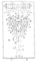
- FIG. 8 shows an isoline diagram of the film efficiency ⁇ f, ad obtained on the wall surface 1 when the parameters including the dimensions and ratios shown in FIGS.
- Length ratio Lc / H 0.625
- Main longitudinal angle ⁇ 1 30 ° Long / short axis ratio
- De / D 2.0 at the center of the jet opening
- Ejection angle difference ⁇ 10 °
- Lateral ejection angle ⁇ 32 °
- Straight line length of communication passage outlet S / D 0.2
- Front end position of ejection opening x / D -1.0 (Here, x is the distance from the center point CP where the axis C3 of the main passage 3 and the wall surface 1 shown in FIG. 4 intersect to the downstream of the hot gas G.
- the minus sign is the origin CP. (Indicates the distance in the upstream direction.)
- the cooling medium CL ejected from the ejection opening 2 has a film efficiency of 1.0 in the vicinity of the downstream thereof, a film efficiency of 0.8 in the rear thereof, and a width direction thereof.
- An area with a film efficiency of 0.6 is formed near the center, an area with a film efficiency of 0.4 is formed near the center, and an area with a film efficiency of 0.2 is formed on the outermost side over a wide area.
- the gas turbine includes a compressor that compresses air, a combustor that supplies and burns fuel to the compressed air from the compressor, and a turbine that is driven by high-temperature and high-pressure combustion gas from the combustor.
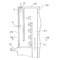
- the turbine has a large number of blades 23 implanted on the outer periphery of a turbine disk 21 shown in FIG.
- Six jet openings 2 are arranged side by side in the radial direction of the rotor blade 23 at a portion slightly rearward from the front edge 25 on the blade surface (wall surface 1) of the rotor blade 23, and these jet openings 2 are arranged adjacent to each other. It faces the hot gas (combustion gas) passage GP between the blades 23.
- a folded cooling medium passage 27 shown in FIG. 10 is formed inside the rotor blade 23, and the ejection opening 2 communicates with a middle portion of the cooling medium passage 27.
- a cooling medium CL composed of air extracted from the compressor is introduced from the passage in the turbine disk 21 to the cooling medium passage 27 and injected from the outlet opening 2, and then the passage from the outlet hole 31 opened to the blade tip 29. It is ejected into the GP. In this way, a film flow CF of the cooling medium C is formed on the blade surface 1 by the cooling medium CL injected from the ejection opening 2 opened on the blade surface which is the wall surface 1 shown in FIG. To be cooled.
- the example in which the plurality of ejection openings 2 are arranged at equal intervals in the vertical direction has been described, but the number and arrangement of the plurality of ejection openings 2 may be appropriately selected.
- two rows in which a plurality of ejection openings 2 are arranged at equal intervals in the radial direction are provided apart from each other in the front-rear direction, and the radial position of the ejection openings 2 in the front row and the ejection openings 2 in the rear row are provided.
- the positions in the radial direction may be shifted from each other.
- the present invention can be widely applied to wall surfaces facing a passage of high-temperature gas, such as a stationary blade and an inner cylinder of a combustor, in addition to a moving blade of a gas turbine.
Landscapes
- Engineering & Computer Science (AREA)
- Mechanical Engineering (AREA)
- General Engineering & Computer Science (AREA)
- Physics & Mathematics (AREA)
- Thermal Sciences (AREA)
- Manufacturing & Machinery (AREA)
- Chemical & Material Sciences (AREA)
- Combustion & Propulsion (AREA)
- Fluid Mechanics (AREA)
- Turbine Rotor Nozzle Sealing (AREA)
- Electrical Discharge Machining, Electrochemical Machining, And Combined Machining (AREA)
Abstract
冷却媒体フイルムが壁面から剥離することを抑制して、壁面を効率的に冷却するとともに、製造が容易なフイルム冷却構造を提供する。高温ガスGの通路に臨む壁面1に設けた噴出開口2に連なる主通路3と、主通路3から分岐した一対の分岐通路4,5と、これら通路を連通する連通路6,7とを有する。一対の分岐通路4,5からの冷却媒体CL4,CL5の噴出方向A,Bは、これら冷却媒体を互いに壁面1に押しつける方向の渦流V1,V2を形成するように、高温ガスGの流れ方向に対して傾斜して設定されている。主通路3および分岐通路4,5の横断面は、同一の一定内径Dを有し、連通路6,7は、一定内径Dを有する真直な円孔群を連ねた包絡面16,17を有する。主通路の軸心C3と壁面1とがなす主縦方向角度α1が、分岐通路4,5の軸心C4,C5と壁面1とがなす分岐縦方向角度α2よりも大きい。
Description
本出願は、2013年5月22日出願の特願2013-108333の優先権を主張するものであり、その全体を参照により本願の一部をなすものとして引用する。
本発明は、ガスタービンエンジンにおける動翼、静翼、燃焼器の内筒などのように高温ガスの通路に臨む壁面に噴出開口を設け、この噴出開口から噴出される冷却媒体を壁面に沿って流すことによって壁面の冷却を行うフイルム冷却構造に関する。
従来、ガスタービンエンジン(以下、単に「ガスタービン」という。)における動翼のような壁面には、同一方向を指向する多数の噴出開口が設けられ、これら噴出開口から噴出される空気のような冷却媒体のフイルム流により、高温ガスに曝される前記壁面を冷却している。このようなフイルム冷却構造として、一般的には、壁に円孔を高温ガスの下流側へ傾斜させて設け、壁面に開口した楕円形の噴出口から冷却媒体を噴出する。しかしこの冷却構造では冷却効率が低いので、これを改良した冷却構造として、例えば、冷却媒体の壁面への噴出口を双葉片形状としたもの(特許文献1)、および一対の噴出口の間に振り分け部を設けたものがある(特許文献2)。
前記特許文献1の冷却構造によれば、冷却媒体を壁面に沿うように幅を広げて冷却効果を高めることができる。これは、壁面上における冷却効率を示すフイルム効率が高くなるためと推測される。ここで、フイルム効率とは、Tgを高温ガスの温度、Tfを壁面の表面温度、Tcを壁面上における冷却媒体の温度としたとき、ηf,ad=(Tg―Tf)/(Tg―Tc)で表される。しかしながら、噴出口の中央部の形状が単純な楕円ではなく、複数の曲率半径を持つ曲線によって形成されているので(段落0016-0017)、製造工数が増大する。また、前記特許文献2では、冷却媒体の壁面からの剥離を抑制してフイルム効率を向上させることはできるが、前記振り分け部が壁面側から見てアンダーカットとなるために、やはり製造工数が増す。
そこで、本発明は、冷却媒体フイルムが壁面から剥離することを抑制して、ガスタービンの動,静翼などの壁面を効率的に冷却することができるとともに、製造が容易なフイルム冷却構造を提供することを目的とする。
上記目的を達成するために、本発明に係るダブルジェット式フイルム冷却構造は、
高温ガスの通路に臨む壁面に、冷却媒体を前記通路の下流側に向けて噴出する噴出開口が設けられ、
前記噴出開口に前記冷却媒体を供給する真直な円孔からなる主通路と、前記主通路上の分岐点から分岐して前記噴出開口を出口とする真直な円孔からなる一対の分岐通路と、前記主通路と分岐通路とを連通して前記噴出開口を出口とする連通路とが壁内に形成され、
前記一対の分岐通路から噴出される冷却媒体の噴出方向が、これら冷却媒体を互いに前記壁面に押しつける方向の渦流を形成するように、前記高温ガスの流れ方向に対して傾斜して設定され、
前記主通路および分岐通路の横断面は、同一の一定内径を有し、
前記連通路は、前記分岐点を通り横断面が前記一定内径を有する真直な円孔群を連ねた包絡面を有し、
前記一対の分岐通路からの各噴出方向の、前記高温ガスの流れ方向に対する前記壁面に沿った横方向噴出角度βが、前記流れ方向を挟んで互いに反対方向を向くように設定され、
前記主通路の軸心方向と前記壁面とがなす主縦方向角度α1が、前記分岐通路の軸心方向と前記壁面とがなす分岐縦方向角度α2よりも大きく設定されている。
この構成によれば、一対の噴出孔からの前記冷却媒体の各噴出方向の、前記高温ガスの流れ方向に対する前記壁面上に沿った横方向噴出角度が、前記流れ方向を挟んで互いに反対方向を向くように設定されているので、高温ガスの流れ方向に沿って、壁面上に冷却媒体の幅広いフイルム流が効果的に形成されて、フイルム効率が向上する。
さらに、主通路の軸心方向と壁面とがなす主縦方向角度α1が、前記分岐通路の軸心方向と前記壁面とがなす分岐縦方向角度α2よりも大きく設定されているので、分岐通路から噴出される冷却媒体が主通路から噴出される冷却媒体によって分離されて、指向性の高い一対の直進流を形成する。この指向性の高い一対の直進流の間には、十分圧力の低い低圧部が生じるので、直進流が形成する渦流により、直進流の周りからこの低圧部に巻き込まれて壁面に向かう強い流れが形成される。このため、冷却媒体が壁面から剥離することが抑制され、壁面上におけるフイルム効率が高められて、壁面が効果的に冷却される。
しかも、主通路および分岐通路の横断面は、同一の一定内径を有し、かつ、主通路と分岐通路を接続する連通路は、分岐点を通り横断面が前記一定内径を有する真直な円孔群を連ねた包絡面を有しているから、単一の円柱状の加工具、例えば放電加工の加工電極によって、主通路、分岐通路および連通路のすべてを壁面側から加工できるので、製造が容易になる。
すなわち、上記構成によれば、高温ガスに曝される壁面上における冷却媒体の剥離を抑制して壁面上に良好なフイルム流を生成することにより壁面の冷却を効率的に行うことができるとともに、冷却構造を容易に形成できる。
本発明のフイルム冷却構造において、前記主縦方向角度α1と分岐縦方向角度α2との角度差δが3~15°であるのが好ましいこの構成によれば、一対の分岐通路の間に主通路の下流部が突出する形となるので、一対の分岐通路から噴出される冷却媒体同士の分離が十分行われて、冷却媒体の直進流間に確実に低圧部が形成され、渦流が冷却媒体の流れを強力に壁面に押し付けて、フイルム効率を向上させる。
本発明のフイルム冷却構造において、前記連通路を形成する前記包絡面の後面部が平坦であるのが好ましい。ここで、「後面部」とは、高温ガスの流れ方向の下流側に位置する面をいう。後面部として単純な平坦面を用いることにより、連通路の形成が容易になる。
本発明のフイルム冷却構造において、前記主通路の前記壁面と直交する直交方向の高さHに対する、前記分岐通路の分岐点の高さLcの比Lc/Hが、0.3~0.9であるのが好ましい。これにより、冷却媒体が主通路から分岐通路に円滑に分岐される。
前記各分岐通路からの前記横方向噴出角度βが10~45°の範囲にあるのが好ましい。また、前記主通路の主縦方向角度α1は10~45°であるのが好ましく、前記一対の分岐通路の出口間の、前記壁面に沿った距離Wは、前記主通路の一定内径Dに対して1.0~5.0Dに設定されているのが好ましい。これら好ましい構成によれば、壁面に向かう強い渦流が生成されて、壁面をより効果的に冷却できる。
本発明にかかる製造方法は、本発明のダブルジェット式フイルム冷却構造を放電加工によって形成する方法であって、
高温ガスの通路に臨む壁面に、所定外径の円柱形の加工電極によって、前記一定内径の主通路を形成するとともに、
前記加工電極を前記主通路の軸心に対して傾斜させながら放電することにより前記連通路から分岐通路までを連続的に形成する。
この方法により、単一の円柱状の加工電極によって、主通路、分岐通路および連通路のすべてを壁面側から加工できるので、製造が容易になる。
高温ガスの通路に臨む壁面に、所定外径の円柱形の加工電極によって、前記一定内径の主通路を形成するとともに、
前記加工電極を前記主通路の軸心に対して傾斜させながら放電することにより前記連通路から分岐通路までを連続的に形成する。
この方法により、単一の円柱状の加工電極によって、主通路、分岐通路および連通路のすべてを壁面側から加工できるので、製造が容易になる。
請求の範囲および/または明細書および/または図面に開示された少なくとも2つの構成のどのような組合せも、本発明に含まれる。特に、請求の範囲の各請求項の2つ以上のどのような組合せも、本発明に含まれる。
本発明は、添付の図面を参考にした以下の好適な実施形態の説明から、より明瞭に理解されるであろう。しかしながら、実施形態および図面は単なる図示および説明のためのものであり、本発明の範囲を定めるために利用されるべきものではない。本発明の範囲は添付の請求の範囲によって定まる。添付図面において、複数の図面における同一の符号は、同一または相当する部分を示す。
以下,本発明の好ましい実施形態を図面に基づいて説明する。
図1は本発明の一実施形態であるダブルジェット式フイルム冷却構造を適用した壁面1の平面図である。壁面1は矢印方向に流れる高温ガスGに曝されており、この壁面1には、高温ガスGの通路GPに空気のような冷却媒体を噴出する噴出開口2が、高温ガスGの流れ方向にほぼ直交する方向(図1の上下方向)に複数並べて配置されている。なお、以下の説明において、高温ガスGの流れ方向に沿った上流側を前側と呼び、下流側を後側と呼ぶ。
図2の拡大平面図に示すように、各噴出開口2は、壁面1を上面とする壁10の内部に形成された主通路3、この主通路3から分岐した分岐通路4,5、および主通路3と分岐通路4,5とを連通する連通路6,7に接続されている。つまり、噴出開口2は、これら通路3~6の出口3a,4a,5a,6a、7aによって形成されている。主通路3は、壁面1と直交する方向から見た平面視において、高温ガスGの流れ方向と平行であり、分岐通路4,5は、主通路3から、高温ガスGの流れ方向に対して横方向(図1の上下方向)に分岐しており、連通路6,7は、主通路3と分岐通路4,5のそれぞれとを、前記流れ方向に対して横方向(図1の上下方向)に連通させている。これらの通路3~7は、主通路3の軸心C3を含み、壁面1に直交する直交面VPに関し、面対称な形状を有し、後述するように、例えば放電加工により形成される。
分岐通路4,5は、主通路3の軸心C3上の同一の分岐点Pから分岐している。分岐通路4,5の壁面1と直交方向から見た分岐角度、つまり図2に表れた分岐角度θは、5~30°が好ましく、10~20°がさらに好ましい。分岐通路出口4a,5aから噴出される冷却媒体CL4,CL5の噴出方向A,Bは、分岐通路4,5の軸心C4,C5と一致しておらず、つぎに述べるように、噴出開口2の形状によって影響される。
分岐通路4,5は、壁面1に沿った面上で、つまり壁面1と直交する方向から見た平面視で、互いに異なる方向を指向するように設定されている。その結果、分岐通路4,5を通る両冷却媒体CL4,CL5は、互いに離間する方向に噴出される。この例では、噴出方向A,Bが、平面視で高温ガスGの流れ方向を挟んで互いに反対方向を向き、かつ、高温ガスGの流れ方向に対する各噴出方向A,Bの、壁面1に沿った横方向噴射角度βが、同一に設定されている。噴出開口2に含まれる分岐通路出口4a,5aは、分岐通路4,5の軸心C4,C5を長軸とする楕円形である。ここで、横方向噴射角度βは、噴出開口2の前端2f、つまり、図2の平面視で、主通路3の軸心C3と噴出開口2の前縁との交点2fを基点として、この前端2fと、分岐通路出口4a,5aの中心O1,O2とを通る直線が軸心C3とがなす角度(壁面1に沿った角度)と定義する。
主通路3における分岐点Pよりも下流側の通路(以下「主通路下流部」という。)30には、主通路3に導入された冷却媒体CLの一部CL3が流入し、出口3aから軸心C3に沿った方向に噴出される。主通路3と分岐通路4,5のそれぞれは、一定内径Dを有する真直な円孔により形成されている。
連通路6,7はそれぞれ、分岐点Pを通る真直な通路群を含んでおり、この通路群を連ねた包絡面により形成されている。通路群を形成する各通路は、横断面が主通路3および分岐通路4,5と同一の一定内径Dを有している。したがって、主通路3の軸心C3方向から見た図3に示すように、連通路出口6a,7aは、主通路出口3aと分岐通路出口4a,5aとをつなぐ滑らかな曲線を描く。各通路3~7を形成する円孔は、図2の右欄に二点鎖線で示されている。
縦断面図である図4に示すように、壁10を貫通して形成された主通路3は、壁10の内表面11に開口して、空気のような冷却媒体CLを壁10の内側から主通路3に導入する導入開口3bを有している。主通路3の軸心C3は、導入開口3bから外表面である壁面1の出口3aへ向かって高温ガスGの流れ方向の下流側に傾斜している。同様に、分岐通路4,5も,その軸心C4,C5が、分岐点Pから出口4a,5aに向かって高温ガスGの流れ方向の下流側に傾斜している。
図2に示したとおり、冷却媒体CL3~CL5は、主通路3および分岐通路4,5の軸心C3~C5に沿って出口3a~5aから、高温ガス通路GPに噴射される。連通路6,7の出口6a,7aからも冷却媒体の一部CL6,CL7が噴出される。図4に示す軸心C3と壁面1とがなす主縦方向角度α1は、分岐通路4,5の軸心C4およびC5とが壁面1とがなす分岐縦方向角度α2よりも大きい。両分岐通路4,5の分岐縦方向角度α2、α2は同一である。なお、分岐通路4,5の軸心C4,C5は、図4の縦断面に対して横方向(図4の表裏面の方向)に傾斜しているので、分岐縦方向角度α2の大きさは、図4では正確に表れていない。この分岐縦方向角度α2は、斜視図である図5に正確に示されており、分岐点Pの真上の壁面1上の仮想点P1と、分岐通路出口4a,5aの中心O1,O2とを通る線に対して、分岐通路4,5の軸心C4,C5がなす角度である。
このように主通路3および分岐通路4,5が壁面1に対して傾斜しており、さらに分岐通路4,5は主通路3に対して横方向に傾斜しているので、図2に示す噴出開口2に含まれる主通路出口3aおよび分岐通路出口4a,5aはすべて、楕円形となる。また、主縦方向角度α1が分岐縦方向角度α2よりも大きいので、分岐通路出口4a,5aが主通路出口3aよりも後方、つまり高温ガスGの下流側に位置する。
連通路6,7を形成する包絡面16,17は、高温ガスGの上流側である前面部16a,17aが、滑らかな曲面であるのに対し、後面部16b、17bは、後方へ向かって幅が広がる平坦面である。したがって、連通路出口6a,7aはそれぞれ、幅Sの直線となる。これら平坦面16b、17bにより、両分岐通路4,5が形状的に明確に分離されるので、分岐通路4,5から噴出される冷却媒体CL4,CL5同士の分離が促進される。
噴出開口2の分岐通路出口4a,5aから噴出される冷却媒体CL4,CL5は、相互に影響し合い、相手方を壁面1に押し付けるように作用する。その様子を、図6、7を参照しながら説明する。図6に示すように、主通路3に導入された冷却媒体CLは、一部が分岐通路4,5に流入する。分岐通路4,5を流れる冷却媒体の大部分が、分岐通路成分CL4,CL5として、横方向噴出角度βを持って分岐通路出口4a,5aから直進的な冷媒流F1,F2となって、高温ガス通路GPに噴出される。特に、分岐通路出口4a,5aの後端4aa,5aaが主通路出口3aの後端3aaよりも後方に位置しているので、分岐通路出口4a,5aにおける主通路出口3aよりも後方に位置する部分から噴出される直進冷媒流F1,F2は、指向性の高い流れとして形成される。
一方、主通路3を通過した冷却媒体CLのうち、主通路下流部30を流れる冷却媒体の大部分は、主通路成分CL3として、出口3aから軸心C3に沿った方向を指向する直進的な主分離流F3となって、高温ガス通路GPに噴出される。この分離流F3は、直進冷媒流F1,F2の間に入って、直進冷媒流F1,F2を分離する作用を持つ。主通路下流部30および分岐通路4,5に流入した冷却媒体CL3~CL5の一部は、連通路6,7に流入し、その出口6a,7aから副分離流F4,F5となって、高温ガス通路GPに噴出され、直進冷媒流F1,F2の分離を促進する。
高温ガス通路GPの、高温ガスGの流れ方向と直交する横断面を図7に示す。主通路下流部30および連通路6,7からの主分離流F3および副分離流F4,F5により、分岐通路4,5からの指向性の高い直進冷媒流F1とF2とが壁面1に平行な方向に分離される結果、直進冷媒流F1,F2間に強い低圧部11が発生する。これにより、各直進冷媒流F1,F2の内側部、つまり互いに対向する部分に、壁面1へ向かう流れが生じる。その結果、直進冷媒流F1,F2に、内側で壁面1へ向かって冷却媒体CLを巻き込むような互いに逆方向の渦流V1,V2が発生する。これらの渦流V1,V2は、それぞれ、直進冷媒流F1,F2を壁面1に押し付けるように作用する。
低圧部11を効果的に発生させることにより渦流V1,V2を形成して、冷却媒体Cを壁面1に押し付ける作用を発揮するために、図6の2つの分岐通路出口4a,5aは互いに適切な距離だけ離間して配設される必要がある。壁面1に臨む噴出開口2における分岐通路出口4a,5aは、分岐通路4,5の軸心C4,C5を長軸とするほぼ楕円形の形状を有する。一対の分岐通路出口4a、5aの中心点O1,O2間の、壁面1に沿った距離Wは、前記一定内径Dに対して、1.0~5.0Dであることが好ましく、1.5~4.0Dであることがより好ましい。前記距離Wが前記範囲よりも短いと、渦流V1,V2同士の分離が困難になり、前記範囲よりも長いと、直進冷媒流F1,F2の直進性が不十分となり、所望の強さの渦流V1,V2が得られない。
また、分岐通路4,5からの噴出方向A,Bが高温ガスGの流れ方向となす横方向噴出角度βは、10~45°の範囲にあることが好ましい。横方向噴出角度βは、20~40°の範囲にあることがより好ましく、25~35°の範囲にあるのがさらに好ましい。横方向噴出角度βが前記範囲未満であると、やはり、渦流V1,V2同士の分離が困難になり、前記範囲を超えると、直進冷媒流F1,F2の直進性が不十分となり、所望の強さの渦流V1,V2が得られない。
両分岐通路4,5からの噴射方向A,Bが高温ガスGの流れ方向となす横方向噴出角度β、βは、互いに異なる大きさとしてもよい。例えば、主通路3の軸心C3が高温ガスGの流れ方向に沿っていない場合、両分岐通路4,5からの噴出方向A,Bを主通路3の軸心C3に対して対称に設定すると、高温ガスGに対する横方向噴出角度βは、両分岐通路4,5間で相違することになる。
図4に示した主通路3の軸心C3と壁面1とがなす主縦方向角度α1は、10~45°の範囲にあることが好ましく、20~40°の範囲にあることがより好ましい。他方、分岐通路4,5と壁面1とがなす分岐縦方向角度α2は、5~40°の範囲にあることが好ましく、10~35°の範囲にあることがさらに好ましい。主縦方向角度α1および分岐噴射角度α2が前記範囲未満であると、図7の渦流V1,V2が壁面1に近づき過ぎ、前記範囲を超えると、渦流V1,V2が壁面1から遠ざかり過ぎるので、所望の強さの渦流V1,V2が得られない。
また、図4の主・分岐縦方向角度α1、α2の角度差δ=α1-α2は、3~15°が好ましく、5~12がさらに好ましい。角度差δが前記範囲から外れると、図6の主通路3からの分離流F3による図7の渦流V1,V2の分離作用が低下し、所望の強さの渦流V1,V2が得られない。
さらに、図4の壁10内の主通路の高さH、つまり壁10の厚さに対する分岐点Pの高さLcの比=Lc/Hは、0.3~0.9が好ましく、0.4~0.8がさらに好ましい。前記比は、主通路3における分岐点Pよりも上流側の部分と主通路3の全長Lとの比に相当する。この長さ比Lc/Hが前記範囲未満であると、図6の主通路3から噴出される分離流F3の直進性が低下して、分岐通路4,5からの直進流F1,F2を分離する作用が低下する。長さ比Lc/Hが前記範囲を超えると、分岐通路4,5への冷却媒体CL4,CL5の供給量が不十分となる。したがって、いずれの場合でも所望の強さの渦流V1,V2が得られない。
主通路3の全長Lは、一定内径Dとの関係において、2~10Dであるのが好ましい。2D未満では、主通路3および分岐通路4,5から噴出される冷却媒体の指向性が低下し、10Dを超えると通路抵抗が増大する。
つぎに、上記冷却構造の製造方法について説明する。図5に示すように、放電加工機の円柱状の加工電極41を用いて、主通路3、分岐通路4,5および連通路6,7のすべてを壁面1側から加工する。加工電極41は、一定内径Dの各通路3ないし7を形成するように、一定内径Dよりも若干小さい所定外径を有する。この加工電極41を用いた放電加工によって、まず、主通路3を形成する。つづいて、加工電極を主通路3の軸心C3に対して傾斜させながら放電することにより、連通路6,7から分岐通路4,5までを連続的に形成する。このように、単一の加工電極41を適宜傾斜させながら連続加工することにより、主通路3、分岐通路4,5および連通路6,7のすべてを壁面1側から加工できるので、冷却構造の製造が容易になる。
以上の冷却構造によれば、図7に示すように、一対の分岐通路4,5からの冷却媒体CL4、CL5が、低圧部11に巻き込まれた渦流V1,V2によって壁面1に押し付けられて、壁面1の広い範囲に接触し、冷却媒体CLのフイルム流が形成される。このようにして冷却媒体CLが壁面1から剥離することが抑制され、壁面1上におけるフイルム効率が高められて、壁面1が効果的に冷却される。
図8は、図2および図4に示す各寸法および比を含むパラメータをつぎの大きさとした場合に、壁面1上に得られるフイルム効率ηf,adの等値線図を示している。
一定内径 D=15mm
壁厚対一定内径比 H/D=3.5
長さ比 Lc/H=0.625
主縦方向角度 α1=30°
噴出開口の中央部の長短軸比 De/D=2.0
噴出角度差 δ=10°
横方向噴出角度 β=32°
連通路出口の直線長さ S/D=0.2
噴出開口の前端位置 x/D=-1.0
(ここで、xは、図4に示す主通路3の軸心C3と壁面1とが交差する中心点CPを原点とし、高温ガスGの下流方向に向かった距離である。マイナス符号は原点CPから上流方向の距離を示す。)
一定内径 D=15mm
壁厚対一定内径比 H/D=3.5
長さ比 Lc/H=0.625
主縦方向角度 α1=30°
噴出開口の中央部の長短軸比 De/D=2.0
噴出角度差 δ=10°
横方向噴出角度 β=32°
連通路出口の直線長さ S/D=0.2
噴出開口の前端位置 x/D=-1.0
(ここで、xは、図4に示す主通路3の軸心C3と壁面1とが交差する中心点CPを原点とし、高温ガスGの下流方向に向かった距離である。マイナス符号は原点CPから上流方向の距離を示す。)
図8から明らかなように、噴出開口2から噴出される冷却媒体CLは、その下流の近傍に、フイルム効率1.0の領域を、その後方にフイルム効率0.8の領域を、その幅方向中央寄りにフイルム効率0.6の領域を、さらにその中央寄りにフイルム効率0.4の領域を、最外側にフイルム効率0.2の領域を、それぞれ広域にわたって形成している。このような極めて高いフイルム効率を有する冷却媒体Cのフイルム流を壁面1に形成することにより、冷却媒体Cの壁面1からの剥離が阻止されて壁面1の効率的な冷却が行われる。
前記パラメータのうち、
Lc/H=0.75、δ=7.5°、β=32°とした場合でも、図8の噴出開口2付近のフイルム効率が10%程度低下するだけで、全体として十分高いフイルム効率が得られることを確認した。また、
Lc/H=0.5、δ=7.5°、β=29°とした場合でも、図8のフイルム効率よりも全体的に10%程度低下するだけで、全体として十分高いフイルム効率が得られることを確認した。さらに、
Lc/H=0.5、δ=5°、β=29°とした場合には、図8のフイルム効率よりも全体的に20%程度低下するが、前記特許文献2の実施形態と同程度の高いフイルム効率が得られることを確認した。
Lc/H=0.75、δ=7.5°、β=32°とした場合でも、図8の噴出開口2付近のフイルム効率が10%程度低下するだけで、全体として十分高いフイルム効率が得られることを確認した。また、
Lc/H=0.5、δ=7.5°、β=29°とした場合でも、図8のフイルム効率よりも全体的に10%程度低下するだけで、全体として十分高いフイルム効率が得られることを確認した。さらに、
Lc/H=0.5、δ=5°、β=29°とした場合には、図8のフイルム効率よりも全体的に20%程度低下するが、前記特許文献2の実施形態と同程度の高いフイルム効率が得られることを確認した。
図9ないし図11は、本発明をガスタービンのタービン翼に適用した実施例を示す。ガスタービンは、空気を圧縮する圧縮機、圧縮機からの圧縮空気に燃料を供給して燃焼させる燃焼器、燃焼器からの高温および高圧の燃焼ガスにより駆動されるタービンを備えている。前記タービンは、図9に示すタービンディスク21の外周に多数の動翼23を植設したものである。動翼23の翼面(壁面1)における前縁25から若干後方寄りの部分に、6つの噴出開口2が動翼23の径方向に並べて配置されており、これら噴出開口2が、隣接する動翼23間の高温ガス(燃焼ガス)通路GPに臨んでいる。
動翼23の内部には、図10に示す折り返した冷却媒体通路27が形成されており、この冷却媒体通路27の中途部に噴出開口2が連通している。圧縮機から抽気された空気からなる冷却媒体CLが、タービンディスク21内の通路から冷却媒体通路27に導入され、噴出開口2から噴射されたのち、翼端29に開口させた噴出孔31から通路GP内に噴出される。こうして、図11に示す壁面1である翼面に開口した噴出開口2から噴射される冷却媒体CLにより、翼面1上に冷却媒体Cのフイルム流CFが形成されて、動翼23が効果的に冷却される。
上記実施例では、複数の噴出開口2を、上下方向1列に等間隔に並べて配置した例について説明したが、複数の噴出開口2の数および配置は適宜選択してよい。例えば、複数の噴出開口2を径方向に等間隔に並べた列を、前後方向に離して2列設けて、前側の列の噴出開口2の径方向位置と、後側の列の噴出開口2の径方向位置とをずらして配置してもよい。
本発明は、ガスタービンの動翼のほかに、静翼、燃焼器の内筒などのように、高温ガスの通路に臨む壁面に対して広く適用できる。
以上のとおり、図面を参照しながら本発明の好適な実施形態を説明したが、本発明の趣旨を逸脱しない範囲内で、種々の追加、変更または削除が可能である。したがって、そのようなものも本発明の範囲内に含まれる。
以上のとおり、図面を参照しながら好適な実施形態を説明したが、当業者であれば、本件明細書を見て、自明な範囲内で種々の変更および修正を容易に想定するであろう。したがって、そのような変更および修正は、請求の範囲から定まる発明の範囲内のものと解釈される。
1 壁面
2 噴出開口
3 主通路
4,5 分岐通路
6,7 連通路
10 壁
16,17 包絡面
A,B 冷却媒体の噴出方向
V1,V2 渦流
CL、CL3~CL7 冷却媒体
D 一定内径
G 高温ガス
GP 高温ガス通路
α1 主縦方向角度
α2 分岐縦方向角度
β 横方向噴出角度
2 噴出開口
3 主通路
4,5 分岐通路
6,7 連通路
10 壁
16,17 包絡面
A,B 冷却媒体の噴出方向
V1,V2 渦流
CL、CL3~CL7 冷却媒体
D 一定内径
G 高温ガス
GP 高温ガス通路
α1 主縦方向角度
α2 分岐縦方向角度
β 横方向噴出角度
Claims (8)
- 高温ガスの通路に臨む壁面に、冷却媒体を前記通路の下流側に向けて噴出する噴出開口が設けられ、
前記噴出開口に前記冷却媒体を供給する真直な円孔からなる主通路と、前記主通路上の分岐点から分岐して前記噴出開口を出口とする真直な円孔からなる一対の分岐通路と、前記主通路と分岐通路とを連通して前記噴出開口を出口とする連通路とが壁内に形成され、
前記一対の分岐通路から噴出される冷却媒体の噴出方向が、これら冷却媒体を互いに前記壁面に押しつける方向の渦流を形成するように、前記高温ガスの流れ方向に対して傾斜して設定され、
前記主通路および分岐通路の横断面は、同一の一定内径を有し、
前記連通路は、前記分岐点を通り横断面が前記一定内径を有する真直な円孔群を連ねた包絡面を有し、
前記一対の分岐通路からの各噴出方向の、前記高温ガスの流れ方向に対する前記壁面に沿った横方向噴出角度βが、前記流れ方向を挟んで互いに反対方向を向くように設定され、
前記主通路の軸心方向と前記壁面とがなす主縦方向角度α1が、前記分岐通路の軸心方向と前記壁面とがなす分岐縦方向角度α2よりも大きく設定されている、
ダブルジェット式フイルム冷却構造。 - 請求項1に記載のフイルム冷却構造において、前記主縦方向角度α1と分岐縦方向角度α2との角度差δが3~15°であるダブルジェット式フイルム冷却構造。
- 請求項1または2に記載のフイルム冷却構造において、前記連通路を形成する前記包絡面の後面部が平坦面であるダブルジェット式フイルム冷却構造。
- 請求項1から3のいずれか一項に記載のフイルム冷却構造において、前記主通路の前記壁面と直交する直交方向の高さHに対する、前記分岐通路の分岐点の高さLcの比Lc/Hが、0.3~0.9であるダブルジェット式フイルム冷却構造。
- 請求項1から4のいずれか一項に記載のフイルム冷却構造において、前記各分岐通路からの前記横方向噴出角度βが10~45°であるダブルジェット式フイルム冷却構造。
- 請求項1から5のいずれか一項に記載のフイルム冷却構造において、前記主通路の主縦方向角度α1が10~45°であるダブルジェット式フイルム冷却構造。
- 請求項1から6のいずれか一項に記載のフイルム冷却構造において、前記一対の分岐通路の出口間の、前記壁面に沿った距離Wが、前記主通路の一定内径Dに対して1.0~5.0Dに設定されているダブルジェット式フイルム冷却構造。
- 請求項1から7のいずれか一項に記載のダブルジェット式フイルム冷却構造を放電加工によって形成する方法であって、
高温ガスの通路に臨む壁面に、所定外径の円柱形の加工電極によって、前記一定内径の主通路を形成するとともに、
前記加工電極を前記主通路の軸心に対して傾斜させながら放電することにより前記連通路から分岐通路までを連続的に形成するダブルジェット式フイルム冷却構造の製造方法。
Priority Applications (4)
| Application Number | Priority Date | Filing Date | Title |
|---|---|---|---|
| CN201480029137.8A CN105308267B (zh) | 2013-05-22 | 2014-05-21 | 双射流式气膜冷却构造及其制造方法 |
| EP14800768.5A EP3000971B1 (en) | 2013-05-22 | 2014-05-21 | Double-jet film cooling structure for a wall and corresponding method of forming |
| CA2912828A CA2912828A1 (en) | 2013-05-22 | 2014-05-21 | Double-jet film cooling structure and method for manufacturing same |
| US14/944,503 US9945233B2 (en) | 2013-05-22 | 2015-11-18 | Double-jet film cooling structure and method for manufacturing same |
Applications Claiming Priority (2)
| Application Number | Priority Date | Filing Date | Title |
|---|---|---|---|
| JP2013108333A JP5530001B1 (ja) | 2013-05-22 | 2013-05-22 | ダブルジェット式フイルム冷却構造とその製造方法 |
| JP2013-108333 | 2013-05-22 |
Related Child Applications (1)
| Application Number | Title | Priority Date | Filing Date |
|---|---|---|---|
| US14/944,503 Continuation US9945233B2 (en) | 2013-05-22 | 2015-11-18 | Double-jet film cooling structure and method for manufacturing same |
Publications (1)
| Publication Number | Publication Date |
|---|---|
| WO2014189092A1 true WO2014189092A1 (ja) | 2014-11-27 |
Family
ID=51175816
Family Applications (1)
| Application Number | Title | Priority Date | Filing Date |
|---|---|---|---|
| PCT/JP2014/063517 Ceased WO2014189092A1 (ja) | 2013-05-22 | 2014-05-21 | ダブルジェット式フイルム冷却構造とその製造方法 |
Country Status (6)
| Country | Link |
|---|---|
| US (1) | US9945233B2 (ja) |
| EP (1) | EP3000971B1 (ja) |
| JP (1) | JP5530001B1 (ja) |
| CN (1) | CN105308267B (ja) |
| CA (1) | CA2912828A1 (ja) |
| WO (1) | WO2014189092A1 (ja) |
Cited By (2)
| Publication number | Priority date | Publication date | Assignee | Title |
|---|---|---|---|---|
| CN105298649A (zh) * | 2015-11-20 | 2016-02-03 | 清华大学 | 一种用于燃气涡轮发动机薄壁热端部件的气膜冷却孔结构 |
| US11359495B2 (en) | 2019-01-07 | 2022-06-14 | Rolls- Royce Corporation | Coverage cooling holes |
Families Citing this family (25)
| Publication number | Priority date | Publication date | Assignee | Title |
|---|---|---|---|---|
| US11313235B2 (en) * | 2015-03-17 | 2022-04-26 | General Electric Company | Engine component with film hole |
| US10208602B2 (en) * | 2015-04-27 | 2019-02-19 | United Technologies Corporation | Asymmetric diffuser opening for film cooling holes |
| CA2933884A1 (en) * | 2015-06-30 | 2016-12-30 | Rolls-Royce Corporation | Combustor tile |
| US10267161B2 (en) * | 2015-12-07 | 2019-04-23 | General Electric Company | Gas turbine engine with fillet film holes |
| US20170298743A1 (en) * | 2016-04-14 | 2017-10-19 | General Electric Company | Component for a turbine engine with a film-hole |
| US10697301B2 (en) | 2017-04-07 | 2020-06-30 | General Electric Company | Turbine engine airfoil having a cooling circuit |
| EP3450682A1 (en) | 2017-08-30 | 2019-03-06 | Siemens Aktiengesellschaft | Wall of a hot gas component and corresponding hot gas component |
| US10648342B2 (en) * | 2017-12-18 | 2020-05-12 | General Electric Company | Engine component with cooling hole |
| CN108843403B (zh) * | 2018-06-13 | 2022-10-25 | 中国科学院宁波材料技术与工程研究所 | 一种在基体表面产生连续气膜的方法 |
| CN108590777B (zh) * | 2018-06-13 | 2021-11-30 | 中国科学院宁波材料技术与工程研究所 | 一种基体表面连续气膜的发生结构 |
| CN109763868B (zh) * | 2019-03-13 | 2020-05-19 | 北京航空航天大学 | 一种新型分叉气膜孔 |
| CN111829009A (zh) * | 2020-07-10 | 2020-10-27 | 中国空气动力研究与发展中心 | 一种基于楔形体的燃料组合喷注结构 |
| CN112443361A (zh) * | 2020-11-04 | 2021-03-05 | 西北工业大学 | 一种用于涡轮叶片的凹坑逆向气膜孔结构 |
| US11674686B2 (en) * | 2021-05-11 | 2023-06-13 | Honeywell International Inc. | Coating occlusion resistant effusion cooling holes for gas turbine engine |
| US11542831B1 (en) | 2021-08-13 | 2023-01-03 | Raytheon Technologies Corporation | Energy beam positioning during formation of a cooling aperture |
| US11913119B2 (en) | 2021-08-13 | 2024-02-27 | Rtx Corporation | Forming cooling aperture(s) in a turbine engine component |
| US11732590B2 (en) | 2021-08-13 | 2023-08-22 | Raytheon Technologies Corporation | Transition section for accommodating mismatch between other sections of a cooling aperture in a turbine engine component |
| US11673200B2 (en) | 2021-08-13 | 2023-06-13 | Raytheon Technologies Corporation | Forming cooling aperture(s) using electrical discharge machining |
| US11813706B2 (en) | 2021-08-13 | 2023-11-14 | Rtx Corporation | Methods for forming cooling apertures in a turbine engine component |
| US11603769B2 (en) | 2021-08-13 | 2023-03-14 | Raytheon Technologies Corporation | Forming lined cooling aperture(s) in a turbine engine component |
| US11898465B2 (en) | 2021-08-13 | 2024-02-13 | Rtx Corporation | Forming lined cooling aperture(s) in a turbine engine component |
| US12123839B2 (en) | 2021-08-13 | 2024-10-22 | Rtx Corporation | Forming and/or inspecting cooling aperture(s) in a turbine engine component |
| WO2023211485A2 (en) * | 2021-10-22 | 2023-11-02 | Raytheon Technologies Corporation | Gas turbine engine article with cooling holes for mitigating recession |
| KR102737646B1 (ko) * | 2022-05-24 | 2024-12-03 | 국립창원대학교 산학협력단 | 터빈 블레이드의 표면 막 냉각홀 구조 및 그 가공방법 |
| CN116085117A (zh) * | 2023-04-10 | 2023-05-09 | 清华大学 | 导向结构 |
Citations (6)
| Publication number | Priority date | Publication date | Assignee | Title |
|---|---|---|---|---|
| JP2001012204A (ja) * | 1999-06-30 | 2001-01-16 | Toshiba Corp | ガスタービン翼 |
| JP2006009785A (ja) * | 2004-06-23 | 2006-01-12 | General Electric Co <Ge> | シェブロンフィルム冷却式壁 |
| JP2008008288A (ja) | 2006-06-29 | 2008-01-17 | United Technol Corp <Utc> | ガスタービンエンジンならびに部品およびその冷却口の形状を最適化する方法 |
| US20110123312A1 (en) * | 2009-11-25 | 2011-05-26 | Honeywell International Inc. | Gas turbine engine components with improved film cooling |
| JP2011247248A (ja) * | 2010-05-28 | 2011-12-08 | General Electric Co <Ge> | 山形フィルム冷却穴を有する物品と関連の加工処理 |
| JP4954309B2 (ja) | 2010-03-24 | 2012-06-13 | 川崎重工業株式会社 | ダブルジェット式フィルム冷却構造 |
Family Cites Families (13)
| Publication number | Priority date | Publication date | Assignee | Title |
|---|---|---|---|---|
| US8733111B2 (en) | 2012-02-15 | 2014-05-27 | United Technologies Corporation | Cooling hole with asymmetric diffuser |
| US9598979B2 (en) | 2012-02-15 | 2017-03-21 | United Technologies Corporation | Manufacturing methods for multi-lobed cooling holes |
| US8689568B2 (en) | 2012-02-15 | 2014-04-08 | United Technologies Corporation | Cooling hole with thermo-mechanical fatigue resistance |
| US8850828B2 (en) | 2012-02-15 | 2014-10-07 | United Technologies Corporation | Cooling hole with curved metering section |
| US8584470B2 (en) | 2012-02-15 | 2013-11-19 | United Technologies Corporation | Tri-lobed cooling hole and method of manufacture |
| US9482100B2 (en) | 2012-02-15 | 2016-11-01 | United Technologies Corporation | Multi-lobed cooling hole |
| US8763402B2 (en) | 2012-02-15 | 2014-07-01 | United Technologies Corporation | Multi-lobed cooling hole and method of manufacture |
| US8707713B2 (en) | 2012-02-15 | 2014-04-29 | United Technologies Corporation | Cooling hole with crenellation features |
| US8683813B2 (en) | 2012-02-15 | 2014-04-01 | United Technologies Corporation | Multi-lobed cooling hole and method of manufacture |
| US9273560B2 (en) | 2012-02-15 | 2016-03-01 | United Technologies Corporation | Gas turbine engine component with multi-lobed cooling hole |
| US9024226B2 (en) | 2012-02-15 | 2015-05-05 | United Technologies Corporation | EDM method for multi-lobed cooling hole |
| US9410435B2 (en) * | 2012-02-15 | 2016-08-09 | United Technologies Corporation | Gas turbine engine component with diffusive cooling hole |
| US9316104B2 (en) * | 2012-10-25 | 2016-04-19 | United Technologies Corporation | Film cooling channel array having anti-vortex properties |
-
2013
- 2013-05-22 JP JP2013108333A patent/JP5530001B1/ja active Active
-
2014
- 2014-05-21 CN CN201480029137.8A patent/CN105308267B/zh active Active
- 2014-05-21 CA CA2912828A patent/CA2912828A1/en not_active Abandoned
- 2014-05-21 WO PCT/JP2014/063517 patent/WO2014189092A1/ja not_active Ceased
- 2014-05-21 EP EP14800768.5A patent/EP3000971B1/en active Active
-
2015
- 2015-11-18 US US14/944,503 patent/US9945233B2/en active Active
Patent Citations (6)
| Publication number | Priority date | Publication date | Assignee | Title |
|---|---|---|---|---|
| JP2001012204A (ja) * | 1999-06-30 | 2001-01-16 | Toshiba Corp | ガスタービン翼 |
| JP2006009785A (ja) * | 2004-06-23 | 2006-01-12 | General Electric Co <Ge> | シェブロンフィルム冷却式壁 |
| JP2008008288A (ja) | 2006-06-29 | 2008-01-17 | United Technol Corp <Utc> | ガスタービンエンジンならびに部品およびその冷却口の形状を最適化する方法 |
| US20110123312A1 (en) * | 2009-11-25 | 2011-05-26 | Honeywell International Inc. | Gas turbine engine components with improved film cooling |
| JP4954309B2 (ja) | 2010-03-24 | 2012-06-13 | 川崎重工業株式会社 | ダブルジェット式フィルム冷却構造 |
| JP2011247248A (ja) * | 2010-05-28 | 2011-12-08 | General Electric Co <Ge> | 山形フィルム冷却穴を有する物品と関連の加工処理 |
Cited By (2)
| Publication number | Priority date | Publication date | Assignee | Title |
|---|---|---|---|---|
| CN105298649A (zh) * | 2015-11-20 | 2016-02-03 | 清华大学 | 一种用于燃气涡轮发动机薄壁热端部件的气膜冷却孔结构 |
| US11359495B2 (en) | 2019-01-07 | 2022-06-14 | Rolls- Royce Corporation | Coverage cooling holes |
Also Published As
| Publication number | Publication date |
|---|---|
| JP2014227914A (ja) | 2014-12-08 |
| EP3000971A1 (en) | 2016-03-30 |
| US20160069192A1 (en) | 2016-03-10 |
| CN105308267A (zh) | 2016-02-03 |
| US9945233B2 (en) | 2018-04-17 |
| CA2912828A1 (en) | 2014-11-27 |
| CN105308267B (zh) | 2017-06-13 |
| JP5530001B1 (ja) | 2014-06-25 |
| EP3000971B1 (en) | 2020-04-08 |
| EP3000971A4 (en) | 2017-03-08 |
Similar Documents
| Publication | Publication Date | Title |
|---|---|---|
| JP5530001B1 (ja) | ダブルジェット式フイルム冷却構造とその製造方法 | |
| JP4954309B2 (ja) | ダブルジェット式フィルム冷却構造 | |
| CN102089498B (zh) | 用于燃气涡轮机的涡轮机叶片和用于制造这样的涡轮机叶片的型芯 | |
| US8079812B2 (en) | Turbine component | |
| EP1788193B1 (en) | Double jet film cooling arrangement | |
| US9228440B2 (en) | Turbine blade airfoils including showerhead film cooling systems, and methods for forming an improved showerhead film cooled airfoil of a turbine blade | |
| US10018053B2 (en) | Turbine blade cooling structure | |
| JP2005186268A (ja) | 案内装置 | |
| JP7188586B2 (ja) | フィルム冷却構造及びガスタービンエンジン用タービン翼 | |
| CN110529191B (zh) | 一种用于改善涡轮冷却效果的冷却结构 | |
| JP6659823B2 (ja) | タービンブレードの冷却配置 | |
| US9562437B2 (en) | Turbine blade airfoils including film cooling systems, and methods for forming an improved film cooled airfoil of a turbine blade | |
| US20160186574A1 (en) | Interior cooling channels in turbine blades | |
| KR20140014252A (ko) | 터빈 동익 | |
| BR102012027855A2 (pt) | aerofólio e motor de turbina a gás | |
| US20130236301A1 (en) | Apparatus And System For Directing Hot Gas | |
| JP2009293411A (ja) | タービン流路面のフィルム冷却構造 | |
| JP2005015923A (ja) | 水噴射式織機の緯入れノズル | |
| EP3085898A1 (en) | Turbine nozzle box | |
| US10208606B2 (en) | Airfoil for turbomachine and airfoil cooling method | |
| JP6583780B2 (ja) | 翼及びこれを備えるガスタービン | |
| US10196905B2 (en) | Airfoil for turbomachine and method of cooling same | |
| US20180216475A1 (en) | Component for a gas turbine engine |
Legal Events
| Date | Code | Title | Description |
|---|---|---|---|
| WWE | Wipo information: entry into national phase |
Ref document number: 201480029137.8 Country of ref document: CN |
|
| 121 | Ep: the epo has been informed by wipo that ep was designated in this application |
Ref document number: 14800768 Country of ref document: EP Kind code of ref document: A1 |
|
| ENP | Entry into the national phase |
Ref document number: 2912828 Country of ref document: CA |
|
| NENP | Non-entry into the national phase |
Ref country code: DE |
|
| WWE | Wipo information: entry into national phase |
Ref document number: 2014800768 Country of ref document: EP |