WO2014192042A1 - Dispositif de test de charge - Google Patents
Dispositif de test de charge Download PDFInfo
- Publication number
- WO2014192042A1 WO2014192042A1 PCT/JP2013/003429 JP2013003429W WO2014192042A1 WO 2014192042 A1 WO2014192042 A1 WO 2014192042A1 JP 2013003429 W JP2013003429 W JP 2013003429W WO 2014192042 A1 WO2014192042 A1 WO 2014192042A1
- Authority
- WO
- WIPO (PCT)
- Prior art keywords
- resistor
- terminal
- phase
- switch
- generator
- Prior art date
- Legal status (The legal status is an assumption and is not a legal conclusion. Google has not performed a legal analysis and makes no representation as to the accuracy of the status listed.)
- Ceased
Links
Images










Classifications
-
- G—PHYSICS
- G01—MEASURING; TESTING
- G01R—MEASURING ELECTRIC VARIABLES; MEASURING MAGNETIC VARIABLES
- G01R31/00—Arrangements for testing electric properties; Arrangements for locating electric faults; Arrangements for electrical testing characterised by what is being tested not provided for elsewhere
- G01R31/40—Testing power supplies
Definitions
- the present invention relates to a load test apparatus.
- Patent Document 1 a load test apparatus for performing a load test of a three-phase AC generator has been proposed.
- an object of the present invention is to provide a load test apparatus capable of easily switching a load test between a three-phase AC generator and a DC power source or a single-phase AC generator.
- a load test apparatus includes a resistor group having first to sixth resistors, and an operation unit having a rotary switch capable of setting a rotational position of at least a first rotational position to a fourth rotational position.
- a load test apparatus provided with one terminal of a first resistor, one terminal of a second resistor, and one terminal of a third resistor connected, and the other terminal of the first resistor And one terminal of the fourth resistor are connected in a state where switching between series and parallel is possible, and the other terminal of the second resistor and one terminal of the fifth resistor are connected in series and parallel.
- the other terminal of the third resistor and the one terminal of the sixth resistor are connected in a state where switching in series and parallel is possible, and the first terminal is connected to the load test apparatus.
- a three-phase AC generator is connected and the rotary position of the rotary switch is adjusted to the first rotation position.
- the current from the R phase of the first three-phase AC generator can flow to the first resistor and the fourth resistor connected in parallel, and the first three-phase AC generator
- the current from the S phase can flow to the second resistor and the fifth resistor connected in parallel, and the current from the T phase of the first three-phase AC generator is connected to the third resistor in parallel.
- the resistor and the sixth resistor can be made to flow, and the load test apparatus is connected to the second three-phase AC generator having a higher voltage than the first three-phase AC generator, and the rotary position of the rotary switch is set to the second rotation.
- the position is adjusted, the current from the R phase of the second three-phase AC generator can flow to the first resistor and the fourth resistor connected in series, and the second three-phase AC generator
- the current from the S phase of the machine is allowed to flow through the second and fifth resistors connected in series, and the second three-phase AC generator T Is allowed to flow through a third resistor and a sixth resistor connected in series, a first DC power supply or a first single-phase AC generator is connected to the load test device, and the rotary switch
- the rotational position is set to the third rotational position, the current from the first DC power source or the first single-phase AC generator can flow to the first to sixth resistors connected in parallel.
- the load test apparatus is connected to a second DC power supply having a voltage higher than that of the first DC power supply or a second single-phase AC generator having a voltage higher than that of the first single-phase AC generator.
- the first resistor and the fourth resistor are connected in series
- the second resistor and the fifth resistor are connected in series
- the third resistor and the sixth resistor are connected.
- the current from the second DC power source or the second single-phase AC generator can be made to flow to the first to sixth resistors.
- Switching the wiring state of the resistor corresponding to the type of power supply is performed according to the rotation position of the rotary switch, so there is no need to manually rewire the resistor according to the type of power source, and it is easy It becomes possible to perform load test switching between a three-phase AC generator and a DC power source or a single-phase AC generator.
- a first short circuit switch to a third short circuit switch that are on / off controlled in conjunction with the rotational position of the rotary switch are further provided, and when the rotational position of the rotary switch is set to the first rotational position or the fourth rotational position, When the other terminals of the fourth to sixth resistors are connected via the first short-circuit switch and the rotary position of the rotary switch is set to the third rotational position, the second short-circuit The other terminals of the first resistor to the third resistor and one terminal of the fourth resistor to the sixth resistor are connected via the switch, and the first resistor is connected to the first resistor via the third short-circuit switch. One terminal of the resistor to the third resistor is connected to the other terminal of the fourth to sixth resistors.
- the first U-phase terminal for connection with the R-phase of the first three-phase AC generator, the first V-phase terminal for connection with the S-phase of the first three-phase AC generator, and the first three-phase AC
- a first W-phase terminal for connection with the T-phase of the generator, a second U-phase terminal for connection with the R-phase of the second three-phase AC generator, and a connection with the S-phase of the second three-phase AC generator 2nd V phase terminal, 2nd W phase terminal for connecting with T phase of 2nd 3 phase alternating current generator, 1st direct current power supply, 2nd direct current power supply, 1st single phase alternating current generator, 2nd single phase alternating current generator
- the first U-phase terminal is connected to the other terminal of the first resistor and one terminal of the fourth resistor, and the first V-phase terminal is connected to the first V terminal.
- the phase terminal is connected to the other terminal of the second resistor and one terminal of the fifth resistor, and the first W-phase terminal is connected to the other terminal of the third resistor and the first terminal.
- the second U-phase terminal is connected to the other terminal of the fourth resistor
- the second V-phase terminal is connected to the other terminal of the fifth resistor
- the second W-phase terminal Is connected to the other terminal of the sixth resistor
- the connection terminal is connected to one terminal of the first to third resistors.
- a load test apparatus is used in the vicinity of the first U-phase terminal, the first V-phase terminal, the first W-phase terminal, the second U-phase terminal, the second V-phase terminal, the second W-phase terminal, and the connection terminal. It has a notation section including notations for explaining the terminals used corresponding to the power source to be tested.
- the terminal portion is located near the first U-phase terminal, the first V-phase terminal, the first W-phase terminal, the second U-phase terminal, the second V-phase terminal, the second W-phase terminal, and the connection terminal. It has a lighting part which lights up corresponding to.
- the rotary switch is further provided with first to third short-circuit switches that are on / off controlled in conjunction with the rotary position of the rotary switch, and the rotary position of the rotary switch is set to the first rotary position or the fourth rotary position.
- the third U-phase terminal for connection to the R phase of the first three-phase AC generator or the second three-phase AC generator, the S of the first three-phase AC generator or the second three-phase AC generator.
- a third V-phase terminal for connection with the phase a third W-phase terminal for connection with the T-phase of the first three-phase AC generator or the second three-phase AC generator, the first DC power supply, the second DC power supply, the second A terminal portion provided with a connection terminal for connection to one terminal of the 1 single-phase AC generator or the second single-phase AC generator, and a first line change switch to a third line change switch;
- the 3U-phase terminal is connected to one of the other terminal of the first resistor and the other terminal of the fourth resistor according to the switch state of the first line changeover switch, and the third V-phase terminal is connected to the second terminal.
- the third W-phase terminal is connected to one of the other terminals of the third resistor and the other terminal of the sixth resistor according to the switch state of the third line changeover switch.
- the connection terminal is connected to one terminal of the first to third resistors.
- each of the two or more resistor groups has a first switch to a sixth switch whose on / off state changes according to an on / off state of a switch provided in the operation unit.
- a first switch connected to one of the terminals of the first resistor, a second switch connected to one of the terminals of the second resistor, and a third switch connected to one of the terminals of the third resistor.
- the fourth switch is connected to one of the terminals of the fourth resistor, the fifth switch is connected to one of the terminals of the fifth resistor, and the sixth switch is the terminal of the sixth resistor. Connected to either.
- the first switch is connected to one terminal of the first resistor
- the second switch is connected to one terminal of the second resistor
- the third switch is connected to one terminal of the third resistor.
- the fourth switch is connected to one terminal of the fourth resistor
- the fifth switch is connected to one terminal of the fifth resistor
- the sixth switch is connected to one terminal of the sixth resistor.
- a resistor array in which a plurality of resistors are arranged is arranged in a plurality of stages, and the resistor constituting at least one stage of the resistor array is a spare, and the resistance of the other stage of the resistor array
- the resistors constituting the device array are used as the first to sixth resistors.
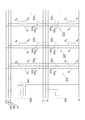
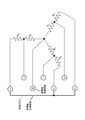
- FIG. 7 shows details of FIG. 6, and is a circuit diagram of a first resistor group, a seventh resistor group, and first to third short-circuit switches in a resistor section. It is a schematic diagram which shows the structure of an operation part. It is a schematic diagram which shows the structure of a terminal part.
- the first short-circuit switch, the resistance part in the state where the first switch to the sixth switch of the first resistor group are turned on (the first resistor group to the first resistor group) 3 is a circuit diagram of a three-resistor group, a first short-circuit switch to a third short-circuit switch.
- FIG. 6 is a circuit diagram of the first resistor group in a state where the first short circuit switch and the first switch to the sixth switch of the first resistor group are turned on for a load test of the first three-phase AC generator. .
- FIG. 6 is a circuit diagram of the first resistor group in a state where the first to sixth switches of the first resistor group are turned on for a load test of the second three-phase AC generator.
- FIG. 3 is a circuit diagram of a third resistor group, a first short circuit switch to a third short circuit switch.
- the circuit diagram of the first resistor group in a state where the second short circuit switch, the third short circuit switch, and the first switch to the sixth switch of the first resistor group are turned on for the load test of the first DC power source. It is.
- the first short-circuit switch, the resistance part in the state where the first switch to the sixth switch of the first resistor group are turned on (the first resistor group to the third resistor)
- FIG. 3 is a circuit diagram of a group, a first short-circuit switch to a third short-circuit switch).
- FIG. 10 is a circuit diagram of the first resistor group in a state where the first short circuit switch and the first switch to the sixth switch of the first resistor group are turned on for a load test of the second DC power supply. It is a figure which shows the example which provided the description part in the terminal part. It is a figure which shows the example which provided the description part and the lighting part in the terminal part.
- FIG. 6 is a circuit diagram of a first resistor group, a seventh resistor group, and a first short-circuit switch to a third short-circuit switch in a resistor section provided with a first on-off switch to a third on-off switch. It is a schematic diagram which shows the structure of the terminal part in 2nd Embodiment.
- FIG. 3 is a circuit diagram of a first resistor group to a third resistor group, a first short circuit switch to a third short circuit switch, and a first line change switch to a third line change switch.
- the resistance unit (the first resistor group to the first resistor group) in the state where the first switch to the sixth switch of the first resistor group are turned on.
- FIG. 3 is a circuit diagram of a third resistor group, a first short-circuit switch to a third short-circuit switch, a first line change-over switch to a third line change-over switch).
- FIG. 5 is a circuit diagram of (first resistor group to third resistor group, first short circuit switch to third short circuit switch, first line change switch to third line change switch).
- FIG. 4 is a circuit diagram of a group to a third resistor group, a first short-circuit switch to a third short-circuit switch, and a first line switch to a third line switch.
- FIG. 7 is a circuit diagram of a first resistor group, a seventh resistor group, and a first short-circuit switch to a third short-circuit switch in a resistor section when the first to sixth switches are arranged close to the neutral point side. .
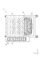
- the dry load test apparatus 1 includes a frame 10, a resistance unit 20, a cooling unit 30, and a connection switching unit 40 (FIGS. 1 to 20).
- the horizontal direction in which the connection switching unit 40 and the frame 10 are arranged is the x direction
- the horizontal direction perpendicular to the x direction is the y direction
- the vertical direction perpendicular to the x direction and the y direction is the z direction.
- the frame 10 houses the resistance unit 20 in the upper stage and the cooling unit 30 in the lower stage. Further, a connection switching unit 40 is provided on the side of the frame 10, and a caster is provided on the lower part. In the side view of FIG. 2, the resistance portion 20 provided inside is indicated by a dotted line.
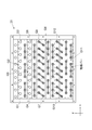
- the resistor section 20 is a series of resistor arrays in which a plurality of rod-shaped resistors R parallel to the y direction are arranged at predetermined intervals in the x direction. It is used to perform a load test of a power source such as a generator connected via a power source.
- the resistor R in the first embodiment, nine resistor rows arranged in the x direction are arranged in 13 stages in the z direction.
- the number of resistors R arranged in each resistor row and the number of stages where the resistor rows are stacked are not limited to this.
- the resistor R in at least one resistor row (the uppermost resistor row in the examples shown in FIGS. 4 and 5) is used for spare purposes such as replacement when another resistor R fails.
- the resistor R constituting the resistor row of the first stage is used as the resistor R (first resistor R 1 to sixth resistor R 6 ) constituting the first resistor group G1 to the twelfth resistor group G12. It is desirable that
- the 6 or 12 resistors R adjacent to each other are set as one resistor group, and the load is applied while changing the number of resistor groups to which a voltage is applied from the power source to be tested. Perform the test.
- connection within the resistor group (the connection state of the resistor R within the resistor group) is changed according to the type of power supply subject to the load test.
- the resistor unit 20 includes a first resistor group G1 to a twelfth resistor group G12, and a first short circuit switch SS1 to a third short circuit switch SS3.
- a first resistor group G1 (rated capacity: 1 kW) having six resistors R with a rated voltage: 400 V and a rated capacity: 1.67 kW, a resistor with a rated voltage: 116 V, and a rated capacity: 334 W
- Second resistor group G2 having six Rs (rated capacity: 2 kW, third resistor group G3 is the same), fourth resistor group G4 having six resistors R having a rated voltage of 116 V and a rated capacity of 834 W (Rated capacity: 5 kW), Rated voltage: 116 V, Rated capacity:
- Fifth resistor group G5 having six resistors R of 1.67 kW (rated capacity: 10 kW, sixth resistor group G6 is the same), rated voltage :
- a seventh resistor group G7 having 12 resistors
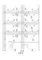
- the first resistor group G1 includes six resistors R (first resistor R 1 to sixth resistor R 6 ) and six switches SW (first switch SW 1 to sixth switch SW 6 ). (See FIG. 7).
- One terminal of the first resistor R 1 to the third resistor R 3 is connected by a short-circuit bar, and is connected to a line (line) from the connection terminal M, which is one of the terminals constituting the terminal unit 43 of the connection switching unit 40. L N ).
- First other terminal of the resistor R 1 is connected via a first switch SW 1 and the fourth switch SW 4, connected to one terminal of the fourth resistor R 4, via a first switch SW 1, It is connected to a line (first U-phase line L U1 ) from the first U-phase terminal U 1 which is one of the terminals constituting the terminal unit 43 of the connection switching unit 40.
- the other terminal of the second resistor R 2 has a second switch SW 2 through the fifth switch SW 5, is connected to one terminal of the fifth resistor R 5, via a second switch SW 2, It is connected to a line (first V-phase line L V1 ) from the first V-phase terminal V 1 which is one of the terminals constituting the terminal unit 43 of the connection switching unit 40.
- the other terminal of the third resistor R 3 includes a third switch SW 3 through the sixth switch SW 6, is connected to one terminal of the sixth resistor R 6, via a third switch SW 3,
- the connection switching unit 40 is connected to a line (first W-phase line L W1 ) from the first W-phase terminal W 1 which is one of the terminals constituting the terminal unit 43.
- the other terminal of the fourth resistor R 4 is connected to a line (second U-phase line L U2 ) from the second U-phase terminal U 2, which is one of terminals constituting the terminal unit 43 of the connection switching unit 40. .
- the other terminal of the fifth resistor R 5 is connected to the line (a 2V-phase line L V2) from the first 2V phase terminal V 2, which is one of the terminals that constitutes the terminal portion 43 of the connection switching section 40 .
- the other terminal of the sixth resistor R 6 is connected to a line (second W-phase line L W2 ) from the second W-phase terminal W 2, which is one of the terminals constituting the terminal unit 43 of the connection switching unit 40. .
- the first switch SW 1 to the third switch SW 3 constitute a triple switch
- the fourth switch SW 4 to the sixth switch SW 6 constitute a triple switch.
- the first switch SW 1 to the sixth switch SW 6 may constitute a six-unit switch.
- the second resistor group G2 to the sixth resistor group G6 include six resistors R (first resistor R 1 to sixth resistor R 6 ) and six switches. because it has a SW (first switch SW 1 ⁇ sixth switch SW 6), description thereof is omitted.
- the resistance value of the resistance value R differs for each resistor group depending on the rated voltage and the rated capacity.
- the seventh resistor group G7 includes six pairs (12) of resistors R (first resistor R 1 to sixth resistor R 6 ) and six switches SW (first switch SW 1 to sixth switch SW). 6 ).
- Two resistors constituting the first resistor R 1 of the seventh resistor group G7 are connected in parallel with the short circuit bar, two resistors constituting the second resistor R 2 is shorting bar It is connected in parallel with the like, two resistors constituting the third resistor R 3 is connected in parallel with the short circuit bar, two resistors constituting the fourth resistor R 4 is It is connected in parallel with the short circuit bar, two resistors constituting the fifth resistor R 5 is connected in parallel with the short circuit bar, two resistors constituting a sixth resistor R 6 The devices are connected in parallel using a shorting bar or the like.
- the eighth resistor group G8 to the twelfth resistor group G12 include six pairs (12) of resistors R (first resistor R 1 to sixth resistor R 6 ). And six switches SW (first switch SW 1 to sixth switch SW 6 ), and the description thereof is omitted.
- the first short-circuiting switch SS1 is a switch for short-circuiting the first 2U-phase line L U2 and the 2V-phase line L V2 the first 2W-phase line L W2.
- the second short-circuit switch SS2 is a switch for short-circuiting the first U-phase line LU1 , the first V-phase line LV1, and the first W-phase line LW1 .
- the third short-circuit switch SS3 is a switch for short-circuiting the second U-phase line LU2 , the second V-phase line LV2 , the second W-phase line LW2, and the line LN .
- Each side of the resistor array is covered with a frame made of an insulating material, and the upper surface and the lower surface are opened to allow the cool air from the cooling unit 30 provided at the lower part to flow upward.
- the resistor array adjacent in the z direction is positioned at a middle position between the resistor R constituting the resistor array and the resistor R adjacent to the resistor R in the x direction.
- the resistors R of each resistor row are arranged so that the resistors R are arranged.
- a cooling unit 30 having a cooling fan is provided below the resistance unit 20 (lower stage of the frame 10).
- the switches (first switch SW 1 to sixth switch SW 6 , first short-circuit switch SS 1 to third short-circuit switch SS 3) constituting the resistance unit 20 and the cooling unit 30 are different from the power source to be tested (load test). Driven by a device driving power source (see FIG. 3).
- the connection switching unit 40 includes an operation unit 41 and a terminal unit 43 (see FIGS. 2, 3, 8, and 9).
- the terminal unit 43 may be arranged at a position away from the operation unit 41 (for example, the back surface of the operation unit 41).
- the operation unit 41 includes a rotary switch 41a, a first operation switch S1 to a twelfth operation switch S12.
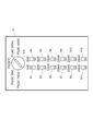
- the rotary switch 41a is used to turn on / off the load test apparatus 1 and to select the type of power source to be tested (switch the mode), and has a first rotation position P1 to a fifth rotation position P5.
- the rotational position of the rotary switch 41a is set to the second rotational position P2. To match.
- the rotational position of the rotary switch 41a is adjusted to the third rotational position P3.
- the rated voltage of the first three-phase AC generator is not limited to the above.
- the number of resistors R and resistor groups G, and the rated voltages and rated capacities thereof, the rated voltage of the first three-phase AC generator is 100 V
- the rated voltage of the second three-phase AC generator is 200 V
- the first A mode in which the rated voltage of the DC power source or the first single-phase AC generator corresponds to 48V and the rated voltage of the second DC power source or the second single-phase AC generator corresponds to 96V is conceivable.
- the first operation switch S1 to the twelfth operation switch S12 are slide type (or toggle type or push button type) operation switches, and the first switches SW 1 to SW1 of the first resistor group G1 to the twelfth resistor group G12, respectively. a switch for performing on-off control of the sixth switch SW 6.
- the first operation switch S1 is turned on, the first switch SW 1 to the sixth switch SW 6 of the first resistor group G1 are turned on (conductive state), and the first resistor group G1 is connected to the terminal portion.
- the current from the power source to be tested connected to the load test apparatus 1 through 43 is made to flow (see FIG. 10).
- the first switch SW 1 to the sixth switch SW 6 of the corresponding resistor group are turned on (conductive state).
- the resistor group is brought into a state in which a current from the power source to be tested connected to the load test apparatus 1 through the terminal portion 43 can flow.
- the cooling fan drive and the first A mode in which the on / off control of the switch SW 1 to the sixth switch SW 6 is performed may be employed.
- the terminal unit 43 is a terminal for connecting a power source to be tested, and is a connection terminal M, a first U-phase terminal U 1 , a first V-phase terminal V 1 , a first W-phase terminal W 1 , a second U-phase terminal U 2 , It has a 2V phase terminal V 2 and a second W phase terminal W 2 .
- the first short-circuit switch SS1 is turned on (conductive or short-circuited), and the cables from the R-phase, S-phase, and T-phase of the first three-phase AC generator are connected. Are connected to the first U-phase terminal U 1 , the first V-phase terminal V 1 , and the first W-phase terminal W 1 , respectively (see FIGS. 10 and 11).
- the cables from the R-phase, S-phase, and T-phase of the second three-phase AC generator are connected to the second U-phase terminal U 2 , the second V-phase terminal V 2 , respectively.
- Connect to the second W-phase terminal W2 see FIGS. 12 and 13).
- the second short-circuit switch SS2 is turned on (conductive or short-circuited), and the third short-circuit switch SS3 is turned on (conductive or short-circuited).
- a cable from one terminal (for example, the negative terminal of the first DC power supply) of the first DC power supply (or the first single-phase AC generator) is connected to the second U-phase terminal U 2 and the second V-phase terminal.
- connection terminal M Connected to any one of V 2 , second W-phase terminal W 2 , and connection terminal M, from the other terminal of the first DC power supply (or first single-phase AC generator) (for example, the positive terminal of the first DC power supply) Is connected to one of the first U-phase terminal U 1 , the first V-phase terminal V 1 , and the first W-phase terminal W 1 (see FIGS. 14 and 15).
- first DC power supply or first single-phase AC generator
- the second DC power supply (or second single-phase AC power generation) is performed with the first short-circuit switch SS1 turned on (conductive or short-circuited).
- the cable from one terminal (for example, the negative terminal of the second DC power supply) of the machine is connected to the connection terminal M and the other terminal (for example, the second single-phase AC generator) (for example, The cable from the positive terminal of the second DC power source) is connected to one of the second U-phase terminal U 2 , the second V-phase terminal V 2 , and the second W-phase terminal W 2 (see FIGS. 16 and 17).
- the on / off states of the first short circuit switch SS1 to the third short circuit switch SS3 are controlled according to the rotational position of the rotary switch 41a, and the first resistor is controlled according to the operation position of the first operation switch S1 to the twelfth operation switch S12.
- the on / off states of the first switch SW 1 to the sixth switch SW 6 of each of the group G1 to the twelfth resistor group G12 are controlled.
- the cables from the R phase, S phase, and T phase of the first three-phase AC generator are connected to the first U phase terminal U 1 , the first V phase terminal V 1 , and the first W phase terminal W 1 , respectively.
- the current from R-phase of the first three-phase AC generator is in a state in which the first resistor R 1 of the first resistor group G1 are connected in parallel may flow to the fourth resistor R 4
- current from the S-phase of the first three-phase AC generator is in a state that can flow through the second resistor R 2 and the fifth resistor R 5 of the first resistor group G1 are connected in parallel
- the first three current from the T-phase phase AC generator is in the state in which the third resistor R 3 of the first resistor group G1 are connected in parallel may flow to a sixth resistor R 6 (FIG. 10, FIG. 11 reference).
- the cables from the R-phase, S-phase, and T-phase of the second three-phase AC generator are connected to the second U-phase terminal U 2 , the second V-phase terminal V 2 , and the second W-phase terminal W 2 , respectively.
- the cable from one terminal of the first DC power source (or the first single-phase AC generator) is connected to the second U-phase terminal U 2 , the second V-phase terminal V 2 , the second W-phase terminal W 2 , and the connection terminal.
- a cable from the other terminal of the first DC power supply (or the first single-phase AC generator) is connected to any one of the M terminals, the first U-phase terminal U 1 , the first V-phase terminal V 1 , and the first W-phase terminal W. 1 is connected, the current from the first DC power source (or the first single-phase AC generator) is supplied to the first resistor R 1 to the first resistor R 1 of the first resistor group G 1 connected in parallel. 6 Resistor R 6 is allowed to flow (see FIGS. 14 and 15).
- a cable from one terminal of the second DC power supply (or second single-phase AC generator) is connected to the connection terminal M, and the other of the second DC power supply (or second single-phase AC generator) is connected.
- the cable from the terminal is connected to any one of the second U-phase terminal U 2 , the second V-phase terminal V 2 , and the second W-phase terminal W 2 , the second DC power supply (or the second single-phase AC generator)
- the first resistor R 1 and the fourth resistor R 4 are connected in series
- the second resistor R 2 and the fifth resistor R 5 are connected in series
- the third resistor R 3 sixth resistor R 6 is connected in series, they are in a state capable of flowing to those connected in parallel when (see FIG. 16, FIG. 17).
- the rotary switch 41 can select three or more operation modes such as the first rotation position P1 to the fifth rotation position P5, and select an appropriate operation mode according to the type and characteristics of the power source to be tested and the generator. Can be performed easily and without error.
- the switching of the wiring state of the resistance unit 20 corresponding to the type of power supply is performed by switching the first short-circuit switch SS1 to the third short-circuit switch SS3 controlled according to the rotational position of the rotary switch 41a. There is no need to manually rewire the inside of the resistance unit 20 according to the type of power supply, and load test switching between a three-phase AC generator and a DC power supply or a single-phase AC generator (according to the power supply to be tested) Wiring switching) can be performed.
- the terminal unit 43 may have a form in which only the name of the terminal is written, but for the purpose of making it easy to understand which terminal is connected, the first U-phase terminal U 1 In the vicinity of the first V-phase terminal V 1 , the first W-phase terminal W 1 , the second U-phase terminal U 2 , the second V-phase terminal V 2 , the second W-phase terminal W 2 , and the connection terminal M,
- the form which provides the description part 44 explaining the terminal to be used may be sufficient (refer FIG. 18).
- FIG. 18 shows the use of the first U-phase terminal U 1 , the first V-phase terminal V 1 , and the first W-phase terminal W 1 as the notation 44, and the diagonal character “200 V three-phase AC generator used (96 V DC power supply test) Then, one of the terminals is connected to the positive electrode) ”or a broken line arrow, and the usage of the second U-phase terminal U 2 , the second V-phase terminal V 2 , and the second W-phase terminal W 2 is indicated by slanted characters“ 400V three-phase.
- notation method and notation contents of the notation unit 44 are not limited to those shown in the example of FIG.
- a lighting unit 45 (first lighting unit 45a to seventh lighting unit 45g) is provided in the vicinity of V 2 , the second W-phase terminal W 2 , and the connection terminal M, and a terminal to be used corresponding to the rotational position of the rotary switch 41a.
- the lighting part in the vicinity may be turned on, and the lighting part near the terminal not used (terminal not corresponding to the test target power supply) may be turned off (see FIG. 19).
- test target power supply and the load test apparatus 1 can be easily connected.
- the first on / off switch OSW 1 to the third on / off switch OSW are arranged near the terminal of the terminal portion 43 and on the line connected to the terminal so that an unexpected current does not flow through the load test apparatus 1 during incorrect wiring.
- the on / off switch in the vicinity of the terminal to be used (the terminal to be used corresponding to the power supply to be tested) is turned on to be in a conductive state, and the unused terminal ( An on / off switch in the vicinity of a terminal that does not correspond to the power supply to be tested may be in an off state so as to be unable to conduct (see FIG. 20).
- the first on / off switch OSW 1 is on the first U-phase line L U1 , the first V-phase line L V1 , and the first W-phase line L W1 , and is the first U-phase terminal U 1 , the first V-phase terminal V 1, and the first W-phase.
- a three-way switch which is provided between the terminals W 1 and the second short-circuiting switch SS2.
- the second on / off switch OSW 2 is on the second U-phase line L U2 , the second V-phase line L V2 , and the second W-phase line L W2 , and the second U-phase terminal U 2 , the second V-phase terminal V 2, and the second W-phase a three-way switch which is provided between the terminal W 2 and the first short-circuiting switch SS1 third short circuit switch SS3.
- the third on / off switch OSW 3 is a switch provided on the line LN and between the connection terminal M and the third short-circuit switch SS3.
- the rotation position of the rotary switch 41a is set to the third rotation position P3, the first on / off switch OSW 1 , the second on / off switch OSW 2, and the third on / off switch OSW 3 are turned on. However, one of the second on / off switch OSW 2 and the third on / off switch OSW 3 may be in an off state.
- a terminal (first 1U phase terminal U 1, the 1V phase terminal V 1, the 1W phase terminal W 1) for connecting to the rated voltage lower first three-phase AC generator, the rated terminals for connecting with a voltage higher second three-phase alternating-current generator (first 2U phase terminal U 2, the 2V phase terminal V 2, the 2W phase terminal W 2) and but has been described in the form provided separately
- the third U-phase terminal U 3 , the third V-phase terminal V 3 , and the third W-phase terminal W 3 may be shared (see the second embodiment, FIGS. 21 to 25).
- the terminal portion 43 is provided with one U-phase terminal, one V-phase terminal, one W-phase terminal, and one negative-electrode terminal (third U-phase terminal U 3 , third V Phase terminal V 3 , third W phase terminal W 3 , connection terminal M, see FIG. 21).
- the resistor unit 20 includes a first line change switch to a second switch constituting a triple switch. Three line changeover switches LSW 1 to LSW 3 are provided.
- the line (third U-phase line L U3 ) from the third U-phase terminal U 3 is connected to one of the first U-phase line L U1 and the second U-phase line L U2 via the first line changeover switch LSW 1.
- the line (third V-phase line L V3 ) from the third V-phase terminal V 3 is connected to one of the first V-phase line L V1 and the second V-phase line L V2 via the second line changeover switch LSW 2. and, a line from the 3W phase terminal W 3 (a 3W-phase line L W3) via a third line selector switch LSW 3, to one of the 1W-phase line L W1 and the 2W-phase line L W2 Connecting.
- the on / off state of the first short circuit switch SS1 to the third short circuit switch SS3 and the connection state of the first line switch LSW 1 to the third line switch LSW 3 are controlled.
- the first switch SW 1 to the sixth switch SW 6 of each of the first resistor group G1 to the twelfth resistor group G12 are turned on / off according to the operation positions of the operation switches S1 to S12 (first resistor).
- the conduction state of the group G1 to the twelfth resistor group G12) is controlled.
- the cables from the R-phase, S-phase, and T-phase of the first three-phase AC generator are connected to the third U-phase terminal U 3 , the third V-phase terminal V 3 , and the third W-phase terminal W 3 , respectively.
- the current from R-phase of the first three-phase AC generator is in a state in which the first resistor R 1 of the first resistor group G1 are connected in parallel may flow to the fourth resistor R 4, current from the S-phase of the first three-phase AC generator is in a state that can flow through the second resistor R 2 and the fifth resistor R 5 of the first resistor group G1 are connected in parallel, the first three current from the T-phase phase AC generator is in the state in which the third resistor R 3 of the first resistor group G1 are connected in parallel may flow to a sixth resistor R 6 (see FIG. 22).
- the cables from the R phase, S phase, and T phase of the second three-phase AC generator are connected to the third U phase terminal U 3 , the third V phase terminal V 3 , and the third W phase terminal W 3 , respectively.
- a cable from one terminal of the first DC power supply (or first single-phase AC generator) is connected to the connection terminal M, and the other of the first DC power supply (or first single-phase AC generator) is connected.
- the first DC power supply (or the first single-phase AC generator)
- From the first resistor group G1 connected in parallel to the first resistor R 1 to the sixth resistor R 6 (see FIG. 24).
- a cable from one terminal of the second DC power supply (or second single-phase AC generator) is connected to the connection terminal M, and the other of the second DC power supply (or second single-phase AC generator) is connected.
- the cable from the terminal is connected to any one of the third U-phase terminal U 3 , the third V-phase terminal V 3 , and the third W-phase terminal W 3 , the second DC power supply (or the second single-phase AC generator)
- the first resistor R 1 and the fourth resistor R 4 are connected in series
- the second resistor R 2 and the fifth resistor R 5 are connected in series
- the third resistor R 3 sixth resistor R 6 is connected in series, they are in a state capable of flowing to those connected in parallel when (see Fig. 25).
- the second embodiment it is possible to minimize the number of terminals provided in the terminal portion 43 and facilitate the connection between the power source to be tested and the load test apparatus 1.
- the first switch SW 1 to the sixth switch SW 6 of each resistor group are connected to one of the first resistor R 1 to the sixth resistor R 6.
- the first switch SW 1 to the sixth switch SW 6 are provided on the side closer to the neutral point.
Landscapes
- Physics & Mathematics (AREA)
- General Physics & Mathematics (AREA)
- Tests Of Circuit Breakers, Generators, And Electric Motors (AREA)
Abstract
[Problème] Réaliser un dispositif de test de charge dans lequel la commutation du câblage peut être mise en oeuvre aisément. [Solution] L'invention concerne un groupe de résistances comprenant une première à une sixième résistance et un module de commande muni d'un commutateur rotatif pouvant régler la position de rotation sur au moins une première à une quatrième position de rotation. Une borne de la première résistance, une borne de la deuxième résistance et une borne de la troisième résistance sont raccordées entre elles; l'autre borne de la première résistance et une borne de la quatrième résistance sont raccordées dans un état qui permet une commutation série/parallèle; l'autre borne de la deuxième résistance et une borne de la cinquième résistance sont raccordées dans un état qui permet une commutation série/parallèle; l'autre borne de la troisième résistance et une borne de la sixième résistance sont raccordées dans un état qui permet une commutation série/parallèle; une première source d'alimentation CC est raccordée au dispositif de test de charge; et lorsque la position de rotation du commutateur rotatif est réglée sur la troisième position de rotation, l'état est tel que le courant électrique provenant de la première source d'alimentation CC peut circuler vers la première à la sixième résistance raccordées en parallèle.
Priority Applications (3)
| Application Number | Priority Date | Filing Date | Title |
|---|---|---|---|
| JP2013541085A JP5395316B1 (ja) | 2013-05-30 | 2013-05-30 | 負荷試験装置 |
| PCT/JP2013/003429 WO2014192042A1 (fr) | 2013-05-30 | 2013-05-30 | Dispositif de test de charge |
| TW103117799A TWI476426B (zh) | 2013-05-30 | 2014-05-21 | 負載測試裝置 |
Applications Claiming Priority (1)
| Application Number | Priority Date | Filing Date | Title |
|---|---|---|---|
| PCT/JP2013/003429 WO2014192042A1 (fr) | 2013-05-30 | 2013-05-30 | Dispositif de test de charge |
Publications (1)
| Publication Number | Publication Date |
|---|---|
| WO2014192042A1 true WO2014192042A1 (fr) | 2014-12-04 |
Family
ID=50112325
Family Applications (1)
| Application Number | Title | Priority Date | Filing Date |
|---|---|---|---|
| PCT/JP2013/003429 Ceased WO2014192042A1 (fr) | 2013-05-30 | 2013-05-30 | Dispositif de test de charge |
Country Status (3)
| Country | Link |
|---|---|
| JP (1) | JP5395316B1 (fr) |
| TW (1) | TWI476426B (fr) |
| WO (1) | WO2014192042A1 (fr) |
Cited By (3)
| Publication number | Priority date | Publication date | Assignee | Title |
|---|---|---|---|---|
| WO2016181680A1 (fr) * | 2015-05-11 | 2016-11-17 | 株式会社辰巳菱機 | Dispositif de mise à l'essai de charge et capuchon de dispositif de mise à l'essai de charge |
| JP2018054636A (ja) * | 2015-01-16 | 2018-04-05 | 株式会社辰巳菱機 | 負荷試験装置 |
| JP6906269B1 (ja) * | 2021-01-25 | 2021-07-21 | 株式会社辰巳菱機 | 負荷試験装置 |
Families Citing this family (2)
| Publication number | Priority date | Publication date | Assignee | Title |
|---|---|---|---|---|
| RU2614652C1 (ru) * | 2014-02-24 | 2017-03-28 | Тацуми Риоки Ко., Лтд | Устройство нагрузочного тестирования и блок переключения соединения для устройства нагрузочного тестирования |
| WO2017072818A1 (fr) * | 2015-10-30 | 2017-05-04 | 株式会社辰巳菱機 | Chauffage de gaine, et dispositif d'essai de charge |
Citations (2)
| Publication number | Priority date | Publication date | Assignee | Title |
|---|---|---|---|---|
| JPH0174569U (fr) * | 1987-11-09 | 1989-05-19 | ||
| JPH0634725A (ja) * | 1992-07-21 | 1994-02-10 | Tatsumi Riyouki:Kk | 切り替え型負荷器セット |
Family Cites Families (3)
| Publication number | Priority date | Publication date | Assignee | Title |
|---|---|---|---|---|
| GB2168555B (en) * | 1984-12-14 | 1987-11-25 | Smiths Industries Plc | Circuit for ensuring correct connection of load to three phase supply |
| US8854032B2 (en) * | 2011-01-12 | 2014-10-07 | Schneider Electric USA, Inc. | System and method for monitoring current drawn by a protected load in a self-powered electronic protection device |
| CN102435869B (zh) * | 2011-08-26 | 2014-03-05 | 东北大学 | 一种三相不平衡负荷自动调补的实验装置及其控制方法 |
-
2013
- 2013-05-30 WO PCT/JP2013/003429 patent/WO2014192042A1/fr not_active Ceased
- 2013-05-30 JP JP2013541085A patent/JP5395316B1/ja active Active
-
2014
- 2014-05-21 TW TW103117799A patent/TWI476426B/zh active
Patent Citations (2)
| Publication number | Priority date | Publication date | Assignee | Title |
|---|---|---|---|---|
| JPH0174569U (fr) * | 1987-11-09 | 1989-05-19 | ||
| JPH0634725A (ja) * | 1992-07-21 | 1994-02-10 | Tatsumi Riyouki:Kk | 切り替え型負荷器セット |
Cited By (8)
| Publication number | Priority date | Publication date | Assignee | Title |
|---|---|---|---|---|
| JP2018054636A (ja) * | 2015-01-16 | 2018-04-05 | 株式会社辰巳菱機 | 負荷試験装置 |
| WO2016181680A1 (fr) * | 2015-05-11 | 2016-11-17 | 株式会社辰巳菱機 | Dispositif de mise à l'essai de charge et capuchon de dispositif de mise à l'essai de charge |
| CN107533104A (zh) * | 2015-05-11 | 2018-01-02 | 株式会社辰巳菱机 | 负载试验装置、负载试验装置的帽 |
| US9885756B2 (en) | 2015-05-11 | 2018-02-06 | Tatsumi Ryoki Co., Ltd | Load testing apparatus and cap for load testing apparatus |
| CN107533104B (zh) * | 2015-05-11 | 2018-06-12 | 株式会社辰巳菱机 | 负载试验装置、负载试验装置的帽 |
| JP6906269B1 (ja) * | 2021-01-25 | 2021-07-21 | 株式会社辰巳菱機 | 負荷試験装置 |
| WO2022157959A1 (fr) * | 2021-01-25 | 2022-07-28 | 株式会社辰巳菱機 | Dispositif de test de charge |
| US12019121B2 (en) | 2021-01-25 | 2024-06-25 | Tatsumi Ryoki Co., Ltd | Load testing device |
Also Published As
| Publication number | Publication date |
|---|---|
| TWI476426B (zh) | 2015-03-11 |
| JPWO2014192042A1 (ja) | 2017-02-23 |
| JP5395316B1 (ja) | 2014-01-22 |
| TW201502549A (zh) | 2015-01-16 |
Similar Documents
| Publication | Publication Date | Title |
|---|---|---|
| JP5497234B1 (ja) | 負荷試験装置 | |
| JP5395316B1 (ja) | 負荷試験装置 | |
| US8536734B2 (en) | Apparatus for inverting DC voltage to AC voltage | |
| JP5797751B2 (ja) | 電圧インバータおよびそのようなインバータの制御方法 | |
| JP2020527323A5 (fr) | ||
| JP2013529055A5 (fr) | ||
| KR20190020053A (ko) | 재구성 가능 mmc 서브모듈 유닛 및 그 제어 유닛 | |
| US11999262B2 (en) | Battery control assembly for a battery system and electric drivetrain for an electric vehicle | |
| JP6757057B1 (ja) | 負荷試験装置 | |
| EP2784527B1 (fr) | Dispositif de test de charge | |
| JP2006067683A (ja) | 蓄電装置 | |
| US9297847B2 (en) | Method for checking a separation point between a photovoltaic inverter and power supply network and photovoltaic inverter | |
| TWI629487B (zh) | 負載測試裝置及電力儲存裝置 | |
| WO2024239575A1 (fr) | Serveur d'échelle de bâti | |
| JP2016024108A (ja) | 負荷試験装置 | |
| JP2013243806A (ja) | 電源装置 | |
| CN102077387B (zh) | 用于高压应用的电池单元设备、连接器和断开器设备及方法 | |
| CN112688291B (zh) | 一种电力电缆交叉互联箱的故障修正装置和方法 | |
| WO2023026427A1 (fr) | Dispositif de test de charge | |
| JP5890341B2 (ja) | 蓄電装置 | |
| WO2024055586A1 (fr) | Ensemble batterie d'alimentation à courant alternatif et procédé de commande | |
| CN216215896U (zh) | 一种电力电缆交叉互联箱的故障修正装置 | |
| CN212229136U (zh) | 一种线路故障诊断模拟盒 | |
| CN223566546U (zh) | 一种开关的进出线接线结构 | |
| CN114914882B (zh) | 电机的保护方法、装置和主动短路保护电路 |
Legal Events
| Date | Code | Title | Description |
|---|---|---|---|
| ENP | Entry into the national phase |
Ref document number: 2013541085 Country of ref document: JP Kind code of ref document: A |
|
| 121 | Ep: the epo has been informed by wipo that ep was designated in this application |
Ref document number: 13886038 Country of ref document: EP Kind code of ref document: A1 |
|
| NENP | Non-entry into the national phase |
Ref country code: DE |
|
| 122 | Ep: pct application non-entry in european phase |
Ref document number: 13886038 Country of ref document: EP Kind code of ref document: A1 |