WO2014192148A1 - Dispositif d'affichage, système d'affichage, dispositif de sortie vidéo et procédé de commande d'un dispositif d'affichage - Google Patents
Dispositif d'affichage, système d'affichage, dispositif de sortie vidéo et procédé de commande d'un dispositif d'affichage Download PDFInfo
- Publication number
- WO2014192148A1 WO2014192148A1 PCT/JP2013/065244 JP2013065244W WO2014192148A1 WO 2014192148 A1 WO2014192148 A1 WO 2014192148A1 JP 2013065244 W JP2013065244 W JP 2013065244W WO 2014192148 A1 WO2014192148 A1 WO 2014192148A1
- Authority
- WO
- WIPO (PCT)
- Prior art keywords
- chromaticity
- display
- value
- backlight
- deterioration
- Prior art date
- Legal status (The legal status is an assumption and is not a legal conclusion. Google has not performed a legal analysis and makes no representation as to the accuracy of the status listed.)
- Ceased
Links
Images






Classifications
-
- G—PHYSICS
- G09—EDUCATION; CRYPTOGRAPHY; DISPLAY; ADVERTISING; SEALS
- G09G—ARRANGEMENTS OR CIRCUITS FOR CONTROL OF INDICATING DEVICES USING STATIC MEANS TO PRESENT VARIABLE INFORMATION
- G09G3/00—Control arrangements or circuits, of interest only in connection with visual indicators other than cathode-ray tubes
- G09G3/20—Control arrangements or circuits, of interest only in connection with visual indicators other than cathode-ray tubes for presentation of an assembly of a number of characters, e.g. a page, by composing the assembly by combination of individual elements arranged in a matrix no fixed position being assigned to or needed to be assigned to the individual characters or partial characters
- G09G3/34—Control arrangements or circuits, of interest only in connection with visual indicators other than cathode-ray tubes for presentation of an assembly of a number of characters, e.g. a page, by composing the assembly by combination of individual elements arranged in a matrix no fixed position being assigned to or needed to be assigned to the individual characters or partial characters by control of light from an independent source
- G09G3/3406—Control of illumination source
-
- G—PHYSICS
- G09—EDUCATION; CRYPTOGRAPHY; DISPLAY; ADVERTISING; SEALS
- G09G—ARRANGEMENTS OR CIRCUITS FOR CONTROL OF INDICATING DEVICES USING STATIC MEANS TO PRESENT VARIABLE INFORMATION
- G09G3/00—Control arrangements or circuits, of interest only in connection with visual indicators other than cathode-ray tubes
- G09G3/20—Control arrangements or circuits, of interest only in connection with visual indicators other than cathode-ray tubes for presentation of an assembly of a number of characters, e.g. a page, by composing the assembly by combination of individual elements arranged in a matrix no fixed position being assigned to or needed to be assigned to the individual characters or partial characters
- G09G3/2003—Display of colours
-
- H—ELECTRICITY
- H04—ELECTRIC COMMUNICATION TECHNIQUE
- H04N—PICTORIAL COMMUNICATION, e.g. TELEVISION
- H04N9/00—Details of colour television systems
- H04N9/64—Circuits for processing colour signals
- H04N9/73—Colour balance circuits, e.g. white balance circuits or colour temperature control
-
- H—ELECTRICITY
- H04—ELECTRIC COMMUNICATION TECHNIQUE
- H04N—PICTORIAL COMMUNICATION, e.g. TELEVISION
- H04N9/00—Details of colour television systems
- H04N9/77—Circuits for processing the brightness signal and the chrominance signal relative to each other, e.g. adjusting the phase of the brightness signal relative to the colour signal, correcting differential gain or differential phase
-
- G—PHYSICS
- G09—EDUCATION; CRYPTOGRAPHY; DISPLAY; ADVERTISING; SEALS
- G09G—ARRANGEMENTS OR CIRCUITS FOR CONTROL OF INDICATING DEVICES USING STATIC MEANS TO PRESENT VARIABLE INFORMATION
- G09G2320/00—Control of display operating conditions
- G09G2320/02—Improving the quality of display appearance
- G09G2320/0233—Improving the luminance or brightness uniformity across the screen
-
- G—PHYSICS
- G09—EDUCATION; CRYPTOGRAPHY; DISPLAY; ADVERTISING; SEALS
- G09G—ARRANGEMENTS OR CIRCUITS FOR CONTROL OF INDICATING DEVICES USING STATIC MEANS TO PRESENT VARIABLE INFORMATION
- G09G2320/00—Control of display operating conditions
- G09G2320/02—Improving the quality of display appearance
- G09G2320/0242—Compensation of deficiencies in the appearance of colours
-
- G—PHYSICS
- G09—EDUCATION; CRYPTOGRAPHY; DISPLAY; ADVERTISING; SEALS
- G09G—ARRANGEMENTS OR CIRCUITS FOR CONTROL OF INDICATING DEVICES USING STATIC MEANS TO PRESENT VARIABLE INFORMATION
- G09G2320/00—Control of display operating conditions
- G09G2320/04—Maintaining the quality of display appearance
- G09G2320/043—Preventing or counteracting the effects of ageing
- G09G2320/048—Preventing or counteracting the effects of ageing using evaluation of the usage time
-
- G—PHYSICS
- G09—EDUCATION; CRYPTOGRAPHY; DISPLAY; ADVERTISING; SEALS
- G09G—ARRANGEMENTS OR CIRCUITS FOR CONTROL OF INDICATING DEVICES USING STATIC MEANS TO PRESENT VARIABLE INFORMATION
- G09G2320/00—Control of display operating conditions
- G09G2320/06—Adjustment of display parameters
- G09G2320/0626—Adjustment of display parameters for control of overall brightness
-
- G—PHYSICS
- G09—EDUCATION; CRYPTOGRAPHY; DISPLAY; ADVERTISING; SEALS
- G09G—ARRANGEMENTS OR CIRCUITS FOR CONTROL OF INDICATING DEVICES USING STATIC MEANS TO PRESENT VARIABLE INFORMATION
- G09G2320/00—Control of display operating conditions
- G09G2320/06—Adjustment of display parameters
- G09G2320/0626—Adjustment of display parameters for control of overall brightness
- G09G2320/0646—Modulation of illumination source brightness and image signal correlated to each other
-
- G—PHYSICS
- G09—EDUCATION; CRYPTOGRAPHY; DISPLAY; ADVERTISING; SEALS
- G09G—ARRANGEMENTS OR CIRCUITS FOR CONTROL OF INDICATING DEVICES USING STATIC MEANS TO PRESENT VARIABLE INFORMATION
- G09G2320/00—Control of display operating conditions
- G09G2320/06—Adjustment of display parameters
- G09G2320/0666—Adjustment of display parameters for control of colour parameters, e.g. colour temperature
-
- G—PHYSICS
- G09—EDUCATION; CRYPTOGRAPHY; DISPLAY; ADVERTISING; SEALS
- G09G—ARRANGEMENTS OR CIRCUITS FOR CONTROL OF INDICATING DEVICES USING STATIC MEANS TO PRESENT VARIABLE INFORMATION
- G09G2320/00—Control of display operating conditions
- G09G2320/08—Arrangements within a display terminal for setting, manually or automatically, display parameters of the display terminal
-
- G—PHYSICS
- G09—EDUCATION; CRYPTOGRAPHY; DISPLAY; ADVERTISING; SEALS
- G09G—ARRANGEMENTS OR CIRCUITS FOR CONTROL OF INDICATING DEVICES USING STATIC MEANS TO PRESENT VARIABLE INFORMATION
- G09G2360/00—Aspects of the architecture of display systems
- G09G2360/14—Detecting light within display terminals, e.g. using a single or a plurality of photosensors
-
- G—PHYSICS
- G09—EDUCATION; CRYPTOGRAPHY; DISPLAY; ADVERTISING; SEALS
- G09G—ARRANGEMENTS OR CIRCUITS FOR CONTROL OF INDICATING DEVICES USING STATIC MEANS TO PRESENT VARIABLE INFORMATION
- G09G2360/00—Aspects of the architecture of display systems
- G09G2360/14—Detecting light within display terminals, e.g. using a single or a plurality of photosensors
- G09G2360/145—Detecting light within display terminals, e.g. using a single or a plurality of photosensors the light originating from the display screen
-
- G—PHYSICS
- G09—EDUCATION; CRYPTOGRAPHY; DISPLAY; ADVERTISING; SEALS
- G09G—ARRANGEMENTS OR CIRCUITS FOR CONTROL OF INDICATING DEVICES USING STATIC MEANS TO PRESENT VARIABLE INFORMATION
- G09G3/00—Control arrangements or circuits, of interest only in connection with visual indicators other than cathode-ray tubes
- G09G3/20—Control arrangements or circuits, of interest only in connection with visual indicators other than cathode-ray tubes for presentation of an assembly of a number of characters, e.g. a page, by composing the assembly by combination of individual elements arranged in a matrix no fixed position being assigned to or needed to be assigned to the individual characters or partial characters
- G09G3/34—Control arrangements or circuits, of interest only in connection with visual indicators other than cathode-ray tubes for presentation of an assembly of a number of characters, e.g. a page, by composing the assembly by combination of individual elements arranged in a matrix no fixed position being assigned to or needed to be assigned to the individual characters or partial characters by control of light from an independent source
- G09G3/36—Control arrangements or circuits, of interest only in connection with visual indicators other than cathode-ray tubes for presentation of an assembly of a number of characters, e.g. a page, by composing the assembly by combination of individual elements arranged in a matrix no fixed position being assigned to or needed to be assigned to the individual characters or partial characters by control of light from an independent source using liquid crystals
- G09G3/3611—Control of matrices with row and column drivers
Definitions
- the present invention relates to a display device, a display system, a video output device, and a display device control method.
- the liquid crystal display device is composed of a liquid crystal layer, a backlight device, and the like.
- Such backlight devices for liquid crystal display devices include devices that use white light and devices that emit white light by mixing three primary colors (for example, red, green, and blue).
- white balance chromaticity of white point
- a backlight having three color light sources white balance (chromaticity of white point) is adjusted by changing the balance of luminance of the three colors (see, for example, Patent Document 1).
- the gain for the input video signal is set so that the white balance becomes a desired balance at the time of shipment.
- the device chromaticity was adjusted by the gain obtained.
- the device chromaticity is the chromaticity of the white spot where the luminance is highest in the self-display device, and is the white spot obtained when the maximum power is given to the backlight and the maximum gradation is given to the video signal. It is chromaticity.
- This white spot is also called a native white spot in products and the like.
- the set chromaticity is the white point chromaticity based on the user setting. For this reason, in a display device that maintains a constant luminance, even if the display device changes over time, the chromaticity between the device chromaticity and the set chromaticity is corrected by using the correction value for the white balance at the time of shipment. By keeping the difference constant, the decrease in luminance was reduced.
- LEDs light emitting diodes
- the method of deterioration with time is different from that of a cold cathode tube.
- backlights using LEDs as with backlights using cold-cathode tubes, even if the white balance correction set at the initial stage is used even after aging, a long time for maintaining the luminance is secured. There was a problem that it was not possible.
- the present invention has been made in view of the above problems, and provides a display device, a video output device, and a display device control method capable of improving the time for maintaining the luminance selected by the user.
- the purpose is to do.
- the display device has the most brightness in the display device, the deterioration value indicating the degree of deterioration of the backlight, the set chromaticity which is the chromaticity of the white point based on the user setting, and the display device.
- a generation unit that generates display chromaticity that is the chromaticity of the white point displayed on the display device based on the device chromaticity that is the chromaticity of the white point that increases, and the display chromaticity is the deterioration
- the set chromaticity approaches the device chromaticity.
- a display system is a display system having a display device and a video output device, wherein the display device has a backlight having a light source, and a drive unit for driving the backlight.
- the video output device includes a deterioration value indicating a degree of deterioration of the backlight, a set chromaticity that is a chromaticity of a white point based on a user setting, and a white that has the highest luminance in the display device.
- a generation unit that generates display chromaticity that is the chromaticity of a white point displayed on the display device based on the device chromaticity that is a chromaticity of a point, and a drive that drives a gain of a video signal or the backlight
- a video signal adjustment unit that adjusts a value based on the display chromaticity generated by the generation unit, and the display chromaticity increases as the degree of deterioration indicated by the deterioration value increases. Closer toward the device chromaticity from.
- the video output device has a deterioration value indicating the degree of deterioration of the backlight, a set chromaticity that is a chromaticity of a white point based on a user setting, and the brightness of the display device.
- a generation unit that generates display chromaticity that is the chromaticity of the white point displayed on the display device based on the device chromaticity that is the chromaticity of the white point that increases, and the gain of the video signal or the backlight
- a video signal adjusting unit that adjusts a driving value for driving the video signal based on the display chromaticity generated by the generating unit, and the video signal or the driving value after the video signal adjusting unit adjusts the backlight.
- the display chromaticity approaches the device chromaticity from the set chromaticity as the degree of deterioration indicated by the deterioration value increases.
- a display device control method includes a deterioration value indicating a degree of backlight deterioration, a set chromaticity that is a chromaticity of a white point based on a user setting, and a self-display device. Based on the device chromaticity that is the chromaticity of the white point with the highest luminance, the generation procedure for generating the display chromaticity that is the chromaticity of the white point displayed on the display device, the gain of the video signal or the Adjusting the drive value for driving the backlight based on the display chromaticity generated by the generation procedure, and the display chromaticity increases as the degree of deterioration indicated by the deterioration value increases. , Approaching the device chromaticity from the set chromaticity.
- the display device of the present invention can improve the time for maintaining the brightness selected by the user.
- FIG. 1 is a block diagram of a schematic configuration of a display device according to a first embodiment. It is a figure explaining an example of the composition of the chromaticity control part concerning a 1st embodiment. It is a figure explaining the setting brightness
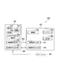
- FIG. 1 is a block diagram of a schematic configuration of a display device 1 according to the present embodiment.
- the display device 1 includes a set luminance designation unit 10, a drive unit 20, a backlight 30, a light detection unit 40, a set chromaticity designation unit 50, a chromaticity control unit 60, a white balance correction unit 70, and A display unit 80 is provided.
- the set brightness specifying unit 10 receives the set brightness set by the user's operation, and outputs the received set brightness to the drive unit 20.
- the set brightness specifying unit 10 includes, for example, a switch and a remote control light receiving unit provided in the main body.
- the set luminance is, for example, K (Kelvin), CIE (Commission Internationale de l'Eclairage)-Y value in the Yxy display system, or the like.
- the drive unit 20 generates a drive value of the backlight 30 based on the set brightness output from the set brightness specifying unit 10 and the detection value output from the light detection unit 40, and the generated drive value is transmitted to the backlight 30. Output to the chromaticity control unit 60. For example, when the drive unit 20 is driven by PWM (Pulse Width Modulation), the generated drive value is a pulse signal.
- PWM Pulse Width Modulation
- the backlight 30 includes an LED (light emitting diode) 31 that is a light source.
- the LED 31 is, for example, a white LED.
- the backlight 30 emits light according to the drive value output by the drive unit 20.
- the backlight 30 is attached to the back surface of the display unit 80, for example. Alternatively, the backlight 30 is attached to the lower part of the display unit 80, and the emitted light is diffused by the light guide plate and the light diffusion film in the display unit 80.
- the light detection unit 40 detects the luminance and chromaticity of a predetermined image displayed on the display device of the backlight 30 or the display unit 80, outputs the detected detection luminance to the drive unit 20, and detects the detected color The degree is output to the chromaticity control unit 60.
- the light detection unit 40 includes color sensors corresponding to the wavelengths of blue, green, and red, detects the luminance and chromaticity of each color, and outputs the detected luminance of each color to the driving unit 20.
- the detected chromaticity of each detected color may be output to the chromaticity control unit 60.
- the light detection unit 40 may always detect the luminance and chromaticity, or may periodically detect the luminance and chromaticity at a predetermined period, or the luminance may be detected by the user.
- the light detection unit 40 may be attached to the display unit 80 only when the luminance is measured. Note that the timing detected by the light detection unit 40 may be a predetermined cycle, a predetermined date and time, random, or when designated by the user.
- the set chromaticity designation unit 50 receives the set chromaticity set by the user's operation and outputs the received set chromaticity to the chromaticity control unit 60.
- the set chromaticity designation unit 50 includes, for example, a switch and a remote control light receiving unit provided in the main body.
- the set chromaticity is, for example, the (x, y) value in the CIE-Yxy display system, the u * and v * values in the L * u * v * display system, the ratio of each color of RGB, and the like.
- the set chromaticity is the chromaticity of the white point based on the user setting set by the user.
- the chromaticity control unit 60 calculates the display chromaticity based on the set chromaticity output from the set chromaticity designation unit 50, the drive value output from the drive unit 20, and the detected chromaticity output from the light detection unit 40.
- the calculated display chromaticity is output to the white balance correction unit 70.
- the display chromaticity is the white point chromaticity displayed on the display device 1.
- the white balance correction unit 70 controls the gain of an externally input video signal (hereinafter referred to as video gain) according to the display chromaticity output from the chromaticity control unit 60, and displays the controlled video signal on the display unit 80.
- video gain an externally input video signal
- the white balance correction unit 70 is a video signal adjustment unit that adjusts the gain of the video signal based on the display chromaticity that is a correction value generated by the chromaticity control unit 60 that is a generation unit.
- the display unit 80 displays an image according to the control of the white balance correction unit 70.
- the display unit 80 is, for example, a TFT (Thin Film Transistor) type liquid crystal panel.
- the display element mounted on the display unit 80 is a display element other than a liquid crystal system, such as an organic electroluminescence display element, an inorganic electroluminescence display element, PALC (Plasma Address Liquid Crystal), PDP (Plasma Display Panel). Or a projector of FED (Field Emission Display) or DMD (digital micromirror device) type.
- FIG. 2 is a diagram illustrating an example of the configuration of the chromaticity control unit 60 according to the present embodiment.
- the chromaticity control unit 60 includes a device chromaticity estimation unit 601, a BL (backlight) deterioration estimation unit 602, a storage unit 603, and a display chromaticity correction unit 604.
- the device chromaticity estimation unit 601 estimates the device chromaticity by a known method based on the detected chromaticity output from the light detection unit 40, and outputs the estimated device chromaticity to the display chromaticity correction unit 604.
- the device chromaticity is the chromaticity of the white point with the highest luminance in the self-display device 1, and is obtained when the maximum power is given to the backlight and the maximum gradation is given to the video signal.
- the chromaticity of the point This white point is generally referred to as a Native white point.
- the device chromaticity estimation unit 601 has a maximum luminance by a known method based on, for example, the initial characteristics of the backlight 30 or the display unit 80, the light transmission characteristics of the liquid crystal panel when the display unit 80 includes a liquid crystal panel, and the like. Chromaticity is estimated as device chromaticity. The maximum luminance is determined by, for example, the relationship between the light emission amount of the backlight 30 and the transmittance of the liquid crystal panel.
- the device chromaticity estimation unit 601 may output the detected chromaticity output from the light detection unit 40 to the BL deterioration estimation unit 602 as the set chromaticity.
- the BL degradation estimation unit 602 acquires the drive value output by the drive unit 20.
- the BL deterioration estimation unit 602 causes the storage unit 603 to store an initial driving value of the backlight 30 (hereinafter referred to as a reference driving value).
- the BL degradation estimation unit 602 determines the degree of degradation of the backlight 30 based on the reference drive value stored in the storage unit 603 and the current drive value output by the drive unit 20 (hereinafter referred to as the current drive value).
- a certain BL degradation value is estimated.
- the BL deterioration estimation unit 602 outputs the estimated BL deterioration value to the display chromaticity correction unit 604. For example, the BL degradation estimation unit 602 calculates a BL degradation value according to the following equation (1).
- the drive value may be an on-time duty, an average value of drive current, an average value of drive voltage, or the like when driven by PWM.
- the storage unit 603 stores reference drive values and target chromaticity correction operation characteristics. The operation characteristics of the target chromaticity correction will be described later.
- the display chromaticity correction unit 604 converts the set chromaticity output from the set chromaticity designation unit 50, the device chromaticity output from the device chromaticity estimation unit 601, and the BL degradation value output from the BL degradation estimation unit 602. Based on this, the set chromaticity and the apparatus chromaticity are mixed to calculate the display chromaticity.
- the display chromaticity correction unit 604 outputs the calculated display chromaticity to the white balance correction unit 70. For example, the display chromaticity correction unit 604 calculates the display chromaticity by the following equation (2).
- the symbol k is a value of BL degradation. Further, the symbol k is a value between 0 and 1, and when 1 is the initial state, it indicates that the deterioration is closer to 0.
- the display chromaticity is obtained by multiplying the BL degradation value by the set chromaticity and the value obtained by subtracting the BL degradation value from 1 and the device chromaticity. It is the added value.
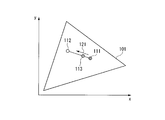
- FIG. 3 is a diagram for explaining the set luminance, the set chromaticity, and the display chromaticity according to the present embodiment.
- FIG. 3 is an XY chromaticity diagram in the CIE 1931 (XYZ) color system, where the horizontal axis represents x and the vertical axis represents y.
- each vertex surrounded by the substantially triangle 101 corresponds to G (green), B (blue), and R (red), respectively.
- An area surrounded by the approximately triangle 101 represents a color space that can be expressed by the display unit 80.
- a point 111 indicates the set chromaticity, and a point 112 indicates the device chromaticity.
- a point 113 indicates the chromaticity after correction.
- the corrected chromaticity is equal to the set chromaticity. That is, in the initial state, the chromaticity control unit 60 does not correct the set chromaticity. For this reason, the position of the point 113 is equal to the position of the point 111.
- the display chromaticity is 0.5 ⁇ set chromaticity + 0.5 ⁇ device chromaticity. That is, the set chromaticity and the device chromaticity are mixed at the same ratio, and the position of the point 113 is in the middle of the straight line connecting the point 111 and the point 112.
- the display chromaticity correction unit 604 generates display chromaticity that is a correction value so as to be placed on a line segment connecting the target chromaticity and the uncorrected chromaticity in a predetermined color space.
- the expression “on the line connecting the target chromaticity and the uncorrected chromaticity” includes the line connecting the point 111 and the point 112 and the vicinity of the line as shown in FIG.
- the line segment connecting the point 111 and the point 112 is shown as an example of a straight line in FIG. 3, but is not limited thereto, and may be a curved line.
- the display chromaticity is equal to the device chromaticity. That is, in a state where deterioration has progressed, the position of the point 113 is equal to the position of the point 112.
- the chromaticity control unit 60 corrects the set chromaticity so as to approach the device chromaticity depending on the degree of deterioration.
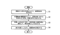
- FIG. 4 for explaining the processing procedure of the chromaticity control unit 60 is a flowchart showing the processing procedure of the chromaticity control unit 60 according to the present embodiment.
- the device chromaticity estimation unit 601 estimates the device chromaticity by a known method based on the detected chromaticity output from the light detection unit 40 and the set chromaticity output from the set chromaticity designation unit 50. Then, the estimated device chromaticity is output to the BL deterioration estimation unit 602.
- Step S ⁇ b> 2 The BL deterioration estimation unit 602 estimates the BL deterioration value by, for example, Expression (1) based on the reference drive value stored in the storage unit 603 and the current drive value output by the drive unit 20. .
- the BL deterioration estimation unit 602 outputs the estimated BL deterioration value to the display chromaticity correction unit 604.
- Step S ⁇ b> 3 The display chromaticity correction unit 604 displays the set chromaticity output from the set chromaticity designation unit 50, the device chromaticity output from the device chromaticity estimation unit 601, and the BL degradation output from the BL degradation estimation unit 602. Based on the value, the display chromaticity is calculated by, for example, Expression (2). The display chromaticity correction unit 604 outputs the calculated display chromaticity to the white balance correction unit 70.
- Step S4 The white balance correction unit 70 controls the video gain for the video signal in accordance with the display chromaticity output from the chromaticity control unit 60, and causes the display unit 80 to display the controlled video signal.
- FIG. 5 is a diagram for explaining a chromaticity correction example according to the present embodiment.
- FIG. 5 is an XY chromaticity diagram in the CIE1931 (XYZ) color system as in FIG. 3, where the horizontal axis represents x and the vertical axis represents y.
- a region surrounded by the approximately triangle 101 represents a color space that can be expressed by the display unit 80.
- a point 201 indicates the device chromaticity in the initial state, and a point 202 indicates the device chromaticity after long-time use. Here, the long time is, for example, several thousand hours.
- a point 204 indicates the set chromaticity set by the first user. Points 203 and 205 indicate display chromaticity corresponding to the point 204.
- a point 203 indicates the display chromaticity in the initial state, and a point 205 indicates the display chromaticity after long-time use.
- a point 207 indicates the set chromaticity set by the second user.
- Points 206 and 208 indicate display chromaticity corresponding to the point 207.
- a point 206 indicates the display chromaticity in the initial state, and a point 208 indicates the display chromaticity after long-time use.
- the display chromaticity moves with the deterioration of the backlight 30.
- the chromaticity control unit 60 moves the point 203 indicating the display chromaticity in the initial state to the point 205 indicating the display chromaticity after using the display chromaticity for a long time as indicated by an arrow 211 in accordance with the deterioration of the backlight 30.
- the display chromaticity for correcting the chromaticity is calculated so as to approach the point 202 indicating the device chromaticity after being used for a long time.
- the chromaticity control unit 60 moves to a point 208 indicating the display chromaticity after using the point 206 indicating the display chromaticity in the initial state for a long time as indicated by an arrow 212 in accordance with the deterioration of the backlight 30.
- the display chromaticity for correcting the chromaticity is calculated so as to be close to the point 202 indicating the device chromaticity after being used for a long time.
- the chromaticity control unit 60 brings the display chromaticity (point 205 and point 208) after different long-time use as shown in FIG. 5 closer to the display chromaticity (point 202) after long-time use, respectively.
- the display chromaticity for correcting the chromaticity is calculated.
- the white balance correction unit 70 corrects the video gain for the video signal according to the calculated display chromaticity, Compared with the conventional case where the luminance is maintained with the initial value of the video gain, the time for maintaining the luminance constant can be extended.
- FIG. 6 is a diagram for explaining an example of a general chromaticity correction method in the display device.
- FIG. 6 is an XY chromaticity diagram in the CIE 1931 (XYZ) color system similar to FIG. Points 201, 202, 203, and 206 are the same as those in FIG.
- the example shown in FIG. 6 is an example in which the correction value for the initial chromaticity is kept unchanged.
- the point 201 which is the initial device chromaticity moves to the point 202, and the points 203 and 206 which are dragged to indicate the display chromaticity in the initial state are the points 205 and 209, respectively.
- the color difference of the point 203 with respect to the point 201 which is the initial device chromaticity is almost the same as the color difference of the point 205 with respect to the point 202 which is the device chromaticity after long-time use.
- the color difference of the point 206 with respect to the point 201 and the color difference of the point 209 with respect to the point 202 are substantially the same.
- FIG. 7 is a diagram for explaining another example of a general chromaticity correction method in the display device.
- FIG. 7 is an XY chromaticity diagram in the CIE 1931 (XYZ) color system similar to FIG. Points 201, 202, 203, and 206 are the same as those in FIG.
- the example shown in FIG. 7 is an example in which the correction value is corrected as needed so that the display chromaticity matches the set chromaticity.
- the display chromaticity and the set chromaticity are matched regardless of the deterioration of the backlight 30. That is, as shown in FIG. 7, a point 203 indicating the display chromaticity in the initial state is matched with a point 231 indicating the display chromaticity after long-time use. Similarly, the point 206 indicating the display chromaticity in the initial state is matched with the point 232 indicating the display chromaticity after long-time use. Also in this case, as in FIG. 6, the point 201 which is the initial device chromaticity moves to a point 202 as the backlight 30 deteriorates.
- the color difference between the device chromaticity and the display chromaticity changes depending on the deterioration of the backlight 30. That is, depending on the set chromaticity, the color difference between the device chromaticity and the display chromaticity increases with long-time use. In this case, the luminance loss due to chromaticity correction increases. To compensate for this, the output of the backlight 30 is increased so as to maintain the brightness of the white spot displayed on the display device, so that the output upper limit of the backlight 30 has been reached in a short time. As a result, the time during which the predetermined luminance can be maintained (the time until the output upper limit of the backlight 30 is reached) has been shortened.
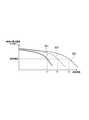
- FIG. 8 is a diagram for explaining an example of the luminance life of each light source using light sources of three primary colors of red, green, and blue.
- the horizontal axis represents the usage time
- the vertical axis represents the maximum luminance of the screen.
- a curve 301 indicates a change in the maximum luminance of the screen with respect to the usage time of the red light source
- a curve 302 indicates a change in the maximum luminance of the screen with respect to a usage time of the green light source
- a curve 303 indicates a change in the maximum luminance of the screen with respect to the usage time of the blue light source. It is.
- the backlight is an LED (light emitting diode) of three colors, red, green, and blue, as shown in FIG. 8, the red LED starts to decrease in brightness first. Then, at the usage time t1, the maximum luminance reaches the designated luminance. Next, the luminance of the green LED starts to decrease, and the maximum luminance reaches the designated luminance at the usage time t2. Finally, the luminance of the blue LED starts to decrease, and the maximum luminance reaches the designated luminance at the usage time t3.
- the luminance of one light source starts to decrease, it is necessary to lower the luminance of the remaining light sources in accordance with the luminance of the light source that has started to decrease in luminance.
- the conventional display device for maintaining the chromaticity constant has a problem that the time during which the luminance can be maintained (hereinafter referred to as luminance life) is extremely short.
- luminance life the time during which the luminance can be maintained
- the display device 1 of the present embodiment uses the estimated BL deterioration value indicating the deterioration of the LED 31 of the backlight 30 so that the corrected chromaticity gradually approaches the device chromaticity after long-time use. To correct. As a result, as described above, the display device 1 of the present embodiment gradually reduces the difference in chromaticity between the corrected chromaticity and the device chromaticity after long-time use, regardless of the set chromaticity. can go. As a result, the display device 1 of the present embodiment shortens the difference in chromaticity between the corrected chromaticity and the device chromaticity after long-time use, and thus extends the luminance life as compared with the conventional display device. be able to. For example, in the display device 1 of the present embodiment, the luminance life is 30,000 hours.
- FIG. 9 is a diagram illustrating an example of the operation of the components of the display device 1 with respect to usage time according to the present embodiment.
- the horizontal axis is the usage time
- the vertical axis of the curve 401 is the video gain
- the vertical axis of the curve 402 is the backlight luminance
- the vertical axis of the curve 403 is the backlight driving power
- the vertical axis of the curve 404 is the display luminance. It is.
- a curve 401 in FIG. 9 represents a change in video gain as the value of k decreases from 1 to a value close to 0 according to the usage time. Further, as indicated by the curve 401, the initial video gain is vg1. Note that the video gain vg1 is a value greater than 0 and less than or equal to 1, for example, 0.7. Also, vg2 and vg3 are values of 1 or less.
- a curve 402 represents a change with the usage time of the luminance of the backlight 30 necessary for obtaining the designated luminance. Further, as indicated by the curve 402, the initial luminance of the backlight 30 is c1.
- a curve 403 represents a change in driving power of the backlight 30 due to deterioration of the backlight 30.
- the driving power of the initial backlight 30 is p1.
- the initial display luminance is c3.
- the initial display luminance c3 is a designated luminance designated in advance by the user or a designated luminance preset in the display device 1.
- the value of k decreases to a value between 1 and 0 at the usage time t1. Therefore, as indicated by the curve 401, the video gain is increased by the white balance correction unit 70 from vg1 to vg2. Accordingly, the brightness of the backlight 30 decreases from c1 to c2 as indicated by a curve 402.
- the drive unit 20 increases the drive value output to the backlight 30 because the detected luminance output from the light detection unit 40 has decreased from c1 to c2.
- the driving power of the backlight 30 at the usage time t1 is increased by the driving unit 20 from p1 to p2. Accordingly, the display device 1 maintains the display brightness c3 as indicated by the curve 404.
- the value of k decreases from 1 to a value close to 0 at the usage time t2 when the backlight 30 has deteriorated. Therefore, as indicated by the curve 401, the video gain is increased by the white balance correction unit 70 from vg2 to vg3. vg3 is a value close to 1, for example 0.9.
- the luminance of the backlight 30 decreases to c3 as indicated by a curve 402.
- the drive unit 20 increases the drive value output to the backlight 30 because the detected luminance output from the light detection unit 40 has decreased to c3.
- the driving power of the backlight 30 at the usage time t2 is increased by the driving unit 20 to p3.
- the drive power p3 is the rated power of the circuit components that constitute the drive unit 20. For this reason, the driving power is saturated at the usage time t2 as indicated by a curve 403.
- the white balance correction unit 70 does not correct the video signal.
- the display device 1 maintains the display brightness c3 as indicated by the curve 404.
- the video gain is increased by the white balance correction unit 70 from vg3 toward a value close to 1.
- the drive power cannot be increased because the drive power is saturated as shown by the curve 403.
- the display luminance of the display device 1 starts to decrease from the designated luminance c3.
- the luminance of the initial backlight 30 is controlled to the maximum luminance as shown in FIG. Control the magnitude of the signal.
- the heat generated by the drive unit is large as described above, and the drive power is saturated at the use time t11.
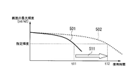
- FIG. 10 is a diagram for explaining an example of the luminance life in the conventional display device and the display device 1 according to the present embodiment.
- the horizontal axis represents the usage time
- the vertical axis represents the luminance life.
- a curve 501 represents display luminance with respect to usage time in the conventional display device
- a curve 502 represents display luminance with respect to usage time in the display device 1 of the present embodiment.
- the luminance life of the conventional display device is a usage time t11, for example, about 8,000 hours.
- the luminance life of the display device 1 of the present embodiment is the usage time t12, for example, about 30,000 hours.
- the use time t2 which can be kept at the designated luminance which is a predetermined luminance can be extended significantly as indicated by an arrow 511 in FIG.
- the display device of the present embodiment has the highest luminance in the display device, the deterioration value indicating the degree of deterioration of the backlight, the set chromaticity that is the chromaticity of the white point based on the user setting, and the display device.
- the display device Based on the device chromaticity that is the chromaticity of the white point, a generation unit that generates display chromaticity that is the chromaticity of the white point displayed on the display device is provided, and the display chromaticity is indicated by a deterioration value.
- the degree of deterioration increases, the set chromaticity approaches the apparatus chromaticity.
- the generation unit increases the color difference between the set chromaticity and the display chromaticity as the degree of deterioration indicated by the deterioration value increases, and the device chromaticity and the display chromaticity are increased. Display chromaticity is generated so as to reduce the color difference.
- the display device of the present embodiment includes a video signal adjustment unit that adjusts the gain of the video signal or the drive value for driving the backlight based on the display chromaticity generated by the generation unit.
- the luminance of the backlight 30 starts to decrease and the chromaticity control unit 60 changes the set chromaticity in the display as the degree of deterioration indicated by the estimated deterioration value increases.
- Display chromaticity is calculated so as to approach chromaticity.
- the white balance correction unit 70 corrects the chromaticity by increasing the video gain based on the display chromaticity output from the chromaticity control unit 60 according to the deterioration.
- the correction amount can be suppressed by bringing the set chromaticity closer to the device chromaticity according to the progress of the deterioration of the light source of the backlight 30.
- the display device 1 of the present embodiment it is possible to extend the usage time that can be maintained at the designated luminance that is the predetermined luminance.
- the display device 1 of the present embodiment corrects the set chromaticity by moving with time as the backlight 30 deteriorates.
- the apparatus chromaticity estimation part 601 demonstrated the example which estimates apparatus chromaticity based on the detection chromaticity which the photon detection part 40 output, it is not restricted to this.
- the device chromaticity estimation unit 601 estimates the device chromaticity using the driving value output from the driving unit 20, the usage time from the initial state in which the backlight 30 is caused to emit light, or a predetermined fixed value. It may be.
- the device chromaticity estimation unit 601 may read a fixed value stored in advance in its own unit and use the read fixed value for the device chromaticity.
- the device chromaticity estimation unit 601 acquires an initial drive value when the LED 31 of the backlight 30 emits light with a predetermined luminance from the drive unit 20 and stores the acquired initial drive value in its own unit. You may do it.
- the device chromaticity estimation unit 601 acquires the current drive value when the LED 31 of the backlight 30 emits light with a predetermined luminance from the drive unit 20, and stores the acquired current drive value and the stored initial drive value.
- the device chromaticity may be estimated based on the above. Further, a value stored in advance corresponding to the BL drive value may be used for the device chromaticity.
- the device chromaticity estimation unit 601 may measure the usage time from the initial state in which the backlight 30 emits light. Then, the BL degradation estimation unit 602 may estimate the device chromaticity based on the measured usage time. Further, a value stored in advance corresponding to the usage time may be used for the apparatus chromaticity.
- the BL degradation estimation part 602 demonstrated the example which estimates the value of BL degradation using the drive value which the drive part 20 output, it is not restricted to this.
- the BL deterioration estimation unit 602 determines the BL based on the detection luminance and detection chromaticity output from the light detection unit 40, the device chromaticity estimated by the device chromaticity estimation unit 601, the usage time from the initial state in which the backlight 30 is emitted, and the like. You may make it guess the value of degradation.
- the BL deterioration estimation unit 602 may store the initial values of the detection luminance and the detection chromaticity output from the light detection unit 40 in the storage unit 603, respectively. Then, the BL degradation estimation unit 602 uses the current detection luminance output from the light detection unit 40 and the initial value of the detection luminance stored in the storage unit 603 to calculate the initial value of the detection luminance and the current detection luminance. The value of BL degradation may be estimated based on the difference or ratio. Similarly, the BL degradation estimation unit 602 uses the current detection chromaticity output from the light detection unit 40 and the initial value of the detection chromaticity stored in the storage unit 603 to determine the initial value of the detection chromaticity and the current value. The BL degradation value may be estimated based on the difference or ratio with the detected chromaticity.
- the BL deterioration estimation unit 602 may measure the usage time from the initial state in which the backlight 30 emits light.
- the storage unit 603 may store a BL deterioration value corresponding to the usage time in advance.
- the BL deterioration estimation unit 602 may estimate the BL deterioration value by reading the BL deterioration value stored in the storage unit 603 corresponding to the measured usage time.
- the BL deterioration estimation unit 602 acquires the device chromaticity estimated by the device chromaticity estimation unit 601, and sets the difference or ratio between the acquired device chromaticity and the current detected chromaticity output by the light detection unit 40. Based on this, the value of BL degradation may be estimated. Alternatively, a BL deterioration value stored in advance corresponding to the device chromaticity and the use time may be used.
- FIG. 11 is a diagram for explaining the value of BL degradation according to the present embodiment.
- the horizontal axis indicates the degree to which the LED 31 of the backlight 30 is not deteriorated
- the vertical axis indicates k that is the value of BL deterioration.
- the degree of no deterioration is the degree when 0% is not deteriorated, and approaches 100% according to the deterioration.
- the straight line 701 is k described in Expression (1), and the value increases in proportion to 0 to 1 in accordance with the degree of deterioration.
- the curves 702 and 703 differ in the manner of change of k with respect to the degree of deterioration in a range including the vicinity where the degree of deterioration is 50% from the straight line 701. For example, when the degree of deterioration is 50%, k is 0.5 on the straight line 701, k is 0.6 on the curved line 702, and k is 0.4 on the curved line 703.
- the BL degradation estimation unit 602 may store in the storage unit 603 in advance an LUT (look-up table) that associates the value of k, which is the BL degradation value, with the degree of degradation shown in FIG. . Then, the BL degradation estimation unit 602 may estimate the BL degradation value using the LUT stored in the storage unit 603 based on the drive value output by the drive unit 20.
- LUT look-up table
- the white balance correction unit 70 corrects the video gain according to the display chromaticity output by the chromaticity control unit 60
- the chromaticity control unit 60 may generate a correction value for changing a drive value for driving the backlight 30 based on the calculated display chromaticity, and output the generated drive value to the drive unit 20.
- the chromaticity control unit 60 may distribute the set chromaticity between the white balance correction unit 70 and the drive unit 20 so as to correct both the video gain and the drive value.
- the white balance correction unit 70 adjusts the drive value for driving the light source of the backlight 30 based on the display chromaticity that is the correction value generated by the chromaticity control unit 60 that is the generation unit. It is.
- FIG. 12 is a diagram illustrating a configuration example of the display system 900 according to the present embodiment.
- the display system 900 includes a video output device 901 and a display device 902.
- the video output device 901 and the display device 902 are connected by a video cable 903 and a control signal cable 904.
- the control signal cable 904 is, for example, a USB (Universal Serial Bus) cable.
- the color sensor 905 is attached to the display device 902.
- the color sensor 905 is a functional unit corresponding to the light detection unit 40 in FIG.
- the color sensor 905 outputs the detected detection brightness to the video output device 901.
- the video output device 901 includes a video signal output unit 911, a control signal input / output unit 912, an operation unit 913, a storage unit 914, a chromaticity control unit 60a, and a white balance correction unit 70a.
- the video output device 901 is, for example, a PC (personal computer).
- the operation unit 913 receives the set brightness and the set chromaticity set by the user's operation, and causes the storage unit 914 to store the received set brightness and the set chromaticity.
- the operation unit 913 includes, for example, a switch and a remote control light receiving unit provided in the main body.
- the storage unit 914 stores set luminance and set chromaticity.
- the chromaticity control unit 60a acquires the detected chromaticity output from the color sensor 905.
- the chromaticity control unit 60a calculates the display chromaticity based on the set chromaticity stored in the storage unit 914, the drive value received from the display device 902, and the acquired detected chromaticity, and the calculated display chromaticity. Is output to the white balance correction unit 70a.
- the configuration of the chromaticity control unit 60a is the same as that of the chromaticity control unit 60 described in the first embodiment. For this reason, the chromaticity control unit 60a calculates the display chromaticity using the formula (2) as in the first embodiment.
- the BL degradation value used for the calculation is not limited to the equation (1) by linear interpolation, but the degradation degree and k value as shown in FIG. May be calculated using an LUT associated with the.
- the white balance correction unit 70a controls the gain of a video signal input from the outside or a video signal generated by itself (hereinafter referred to as a video gain) according to the display chromaticity output from the chromaticity control unit 60a.
- the controlled video signal is output to the video signal output unit 911.
- the video signal output unit 911 outputs the video signal output from the white balance correction unit 70 a to the display device 902 via the video cable 903.
- the control signal input / output unit 912 transmits the set luminance stored in the storage unit 914 and the detection value output from the color sensor 905 to the display device 902 via the control signal cable 904.
- the control signal input / output unit 912 receives information indicating a drive value for driving the backlight 30 a included in the display device 902 from the display device 902 via the control signal cable 904.
- the display device 902 includes a video signal input unit 921, a control signal input / output unit 922, a drive unit 20a, a backlight 30a, and a display unit 80a.
- the drive unit 20a, the backlight 30a, and the display unit 80a are functional units corresponding to the drive unit 20, the backlight 30, and the display unit 80 among the functional units illustrated in FIG.
- the drive unit 20a generates a drive value of the backlight 30a based on the set luminance and the detection value output from the control signal input / output unit 922, and the generated drive value is transmitted to the backlight 30a, the control signal input / output unit 922, and the like. Output to. Note that the drive unit 20a may directly receive the detection value output from the light detection unit 40.
- the backlight 30a emits light according to the driving value output from the driving unit 20a.
- the video signal input unit 921 outputs the video signal received from the video output device 901 to the display unit 80a.
- the control signal input / output unit 922 generates information indicating a drive value based on the drive value output by the drive unit 20a, and transmits the information indicating the generated drive value to the video output device 901 via the control signal cable 904. . Further, the control signal input / output unit 922 receives the set luminance and the detection value from the video output device 901 via the control signal cable 904.
- the display unit 80a displays the video signal received by the video signal input unit 921 from the video output device 901.
- the display system of the present embodiment is a display system having a display device and a video output device, and the display device includes a backlight having a light source and a drive unit that drives the backlight.
- the video output device is a device that has a deterioration value indicating the degree of deterioration of the backlight, a set chromaticity that is a chromaticity of a white point based on a user setting, and a chromaticity of a white point that has the highest luminance in the display device.
- the generation unit that generates the display chromaticity that is the chromaticity of the white point displayed on the display device, and the display that the generation unit generates the drive value for driving the gain of the video signal or the backlight
- a display signal chromaticity that approaches the device chromaticity from the set chromaticity as the degree of deterioration indicated by the deterioration value increases.
- the video output device includes a deterioration value indicating the degree of deterioration of the backlight, a set chromaticity that is a chromaticity of a white point based on a user setting, and a white point having the highest luminance in the display device.
- a generation unit that generates display chromaticity that is the chromaticity of the white point displayed on the display device, and a drive value that drives the gain of the video signal or the backlight
- a video signal adjustment unit that adjusts based on the display chromaticity generated by the unit, and an output unit that outputs the video signal or drive value after adjustment by the video signal adjustment unit to a display device having a backlight
- the display chromaticity approaches the device chromaticity from the set chromaticity as the degree of deterioration indicated by the deterioration value increases.
- the video output device 901 outputs the corrected video signal to the display device 902 according to the display chromaticity.
- the display device 902 transmits information indicating the drive value necessary for calculating the display chromaticity to the video output device 901. Due to such a configuration, the display system 900 of the present embodiment can also improve the time for maintaining the brightness selected by the user, as in the first embodiment.
- the backlight 30 may generate white light by mixing light from three light sources, for example, a red LED, a green LED, and a blue LED.
- the drive unit 20 may have separate drive units for red, green, and blue LEDs.
- white light may be generated by a green LED, a blue LED, and a phosphor that emits light when excited by the two LEDs.
- the drive unit 20 may have separate drive units for the green and blue LEDs.
- the backlight 30 (including 30a) is used as the backlight of the display device 1 (including 902) is described, but the present invention is not limited thereto.
- the backlight 30 (including 30a) may be used, for example, as a light source for a projector or a laser television.
- the display device 1 (including 902) of the present embodiment may be applied to a portable information terminal, a navigation system, a notification indicator, a digital signage (digital signage), and the like.
- a program for realizing the functions of the chromaticity control unit 60 of FIG. 1 or the chromaticity control unit 60a of FIG. 12 of the embodiment is recorded on a computer-readable recording medium, and the program recorded on the recording medium May be read by a computer system and executed to perform processing of each unit.
- the “computer system” includes an OS and hardware such as peripheral devices. Further, the “computer system” includes a homepage providing environment (or display environment) if a WWW system is used.
- the “computer-readable recording medium” is a portable medium such as a flexible disk, a magneto-optical disk, a ROM (Read Only Memory), a CD-ROM, or a USB (Universal Serial Bus) I / F (interface).
- a storage device such as a USB memory or a hard disk built in a computer system.
- the “computer-readable recording medium” includes a medium that holds a program for a certain period of time, such as a volatile memory inside a computer system serving as a server or a client.
- the program may be a program for realizing a part of the functions described above, and may be a program capable of realizing the functions described above in combination with a program already recorded in a computer system.
- SYMBOLS 1 DESCRIPTION OF SYMBOLS 1 ... Display apparatus, 10 ... Setting brightness designation
Landscapes
- Engineering & Computer Science (AREA)
- Physics & Mathematics (AREA)
- Computer Hardware Design (AREA)
- General Physics & Mathematics (AREA)
- Theoretical Computer Science (AREA)
- Multimedia (AREA)
- Signal Processing (AREA)
- Liquid Crystal Display Device Control (AREA)
- Control Of Indicators Other Than Cathode Ray Tubes (AREA)
- Liquid Crystal (AREA)
Abstract
Priority Applications (3)
| Application Number | Priority Date | Filing Date | Title |
|---|---|---|---|
| JP2015519586A JP6138932B2 (ja) | 2013-05-31 | 2013-05-31 | 表示装置、表示システム、映像出力装置、および表示装置の制御方法 |
| PCT/JP2013/065244 WO2014192148A1 (fr) | 2013-05-31 | 2013-05-31 | Dispositif d'affichage, système d'affichage, dispositif de sortie vidéo et procédé de commande d'un dispositif d'affichage |
| US14/894,457 US9779648B2 (en) | 2013-05-31 | 2013-05-31 | Display device for correcting white balance based on degradation and chromaticity control method thereof |
Applications Claiming Priority (1)
| Application Number | Priority Date | Filing Date | Title |
|---|---|---|---|
| PCT/JP2013/065244 WO2014192148A1 (fr) | 2013-05-31 | 2013-05-31 | Dispositif d'affichage, système d'affichage, dispositif de sortie vidéo et procédé de commande d'un dispositif d'affichage |
Publications (1)
| Publication Number | Publication Date |
|---|---|
| WO2014192148A1 true WO2014192148A1 (fr) | 2014-12-04 |
Family
ID=51988216
Family Applications (1)
| Application Number | Title | Priority Date | Filing Date |
|---|---|---|---|
| PCT/JP2013/065244 Ceased WO2014192148A1 (fr) | 2013-05-31 | 2013-05-31 | Dispositif d'affichage, système d'affichage, dispositif de sortie vidéo et procédé de commande d'un dispositif d'affichage |
Country Status (3)
| Country | Link |
|---|---|
| US (1) | US9779648B2 (fr) |
| JP (1) | JP6138932B2 (fr) |
| WO (1) | WO2014192148A1 (fr) |
Cited By (2)
| Publication number | Priority date | Publication date | Assignee | Title |
|---|---|---|---|---|
| US10210819B2 (en) * | 2015-02-13 | 2019-02-19 | Boe Technology Group Co., Ltd. | Tunable backlight device, a display device and a method of driving the same |
| JP2021517976A (ja) * | 2018-04-17 | 2021-07-29 | 京東方科技集團股▲ふん▼有限公司Boe Technology Group Co.,Ltd. | 色度補正方法及び装置、デバイス、表示装置、記憶媒体 |
Families Citing this family (5)
| Publication number | Priority date | Publication date | Assignee | Title |
|---|---|---|---|---|
| WO2014188533A1 (fr) * | 2013-05-22 | 2014-11-27 | Necディスプレイソリューションズ株式会社 | Dispositif d'affichage, système d'affichage, dispositif de sortie d'image et procédé de commande d'un dispositif d'affichage |
| KR102218642B1 (ko) * | 2014-11-27 | 2021-02-23 | 삼성디스플레이 주식회사 | 표시 장치 및 표시 장치의 구동 방법 |
| US10297191B2 (en) | 2016-01-29 | 2019-05-21 | Samsung Display Co., Ltd. | Dynamic net power control for OLED and local dimming LCD displays |
| CN108877688A (zh) * | 2017-05-12 | 2018-11-23 | 京东方科技集团股份有限公司 | 背光亮度控制方法及装置 |
| CN109473077A (zh) * | 2018-12-25 | 2019-03-15 | 惠科股份有限公司 | 一种显示面板的驱动方法、系统及显示装置 |
Citations (4)
| Publication number | Priority date | Publication date | Assignee | Title |
|---|---|---|---|---|
| JP2005164710A (ja) * | 2003-11-28 | 2005-06-23 | Nec Mitsubishi Denki Visual Systems Kk | 画像表示装置 |
| JP2010152375A (ja) * | 2010-02-01 | 2010-07-08 | Sharp Corp | 面照明装置及びそれを備えた液晶表示装置 |
| JP2010152326A (ja) * | 2008-11-27 | 2010-07-08 | Casio Computer Co Ltd | 投影装置、投影方法及びプログラム |
| JP2012230262A (ja) * | 2011-04-26 | 2012-11-22 | Canon Inc | 画像表示装置及びその制御方法 |
Family Cites Families (5)
| Publication number | Priority date | Publication date | Assignee | Title |
|---|---|---|---|---|
| JPH05127620A (ja) | 1991-11-06 | 1993-05-25 | Matsushita Electric Ind Co Ltd | 液晶投写型カラーデイスプレイの調整方法および調整回路 |
| JP2008158454A (ja) * | 2006-12-26 | 2008-07-10 | Sony Corp | 液晶表示装置 |
| RU2442202C1 (ru) * | 2008-03-03 | 2012-02-10 | Шарп Кабусики Кайся | Жидкокристаллическое дисплейное устройство |
| JP4872982B2 (ja) * | 2008-07-31 | 2012-02-08 | ソニー株式会社 | 画像処理回路および画像表示装置 |
| JP2011220823A (ja) * | 2010-04-09 | 2011-11-04 | Seiko Epson Corp | 色測定装置、および、色測定方法 |
-
2013
- 2013-05-31 JP JP2015519586A patent/JP6138932B2/ja active Active
- 2013-05-31 US US14/894,457 patent/US9779648B2/en active Active
- 2013-05-31 WO PCT/JP2013/065244 patent/WO2014192148A1/fr not_active Ceased
Patent Citations (4)
| Publication number | Priority date | Publication date | Assignee | Title |
|---|---|---|---|---|
| JP2005164710A (ja) * | 2003-11-28 | 2005-06-23 | Nec Mitsubishi Denki Visual Systems Kk | 画像表示装置 |
| JP2010152326A (ja) * | 2008-11-27 | 2010-07-08 | Casio Computer Co Ltd | 投影装置、投影方法及びプログラム |
| JP2010152375A (ja) * | 2010-02-01 | 2010-07-08 | Sharp Corp | 面照明装置及びそれを備えた液晶表示装置 |
| JP2012230262A (ja) * | 2011-04-26 | 2012-11-22 | Canon Inc | 画像表示装置及びその制御方法 |
Cited By (3)
| Publication number | Priority date | Publication date | Assignee | Title |
|---|---|---|---|---|
| US10210819B2 (en) * | 2015-02-13 | 2019-02-19 | Boe Technology Group Co., Ltd. | Tunable backlight device, a display device and a method of driving the same |
| JP2021517976A (ja) * | 2018-04-17 | 2021-07-29 | 京東方科技集團股▲ふん▼有限公司Boe Technology Group Co.,Ltd. | 色度補正方法及び装置、デバイス、表示装置、記憶媒体 |
| JP7311434B2 (ja) | 2018-04-17 | 2023-07-19 | 京東方科技集團股▲ふん▼有限公司 | 色度補正方法及び装置、デバイス、表示装置、記憶媒体 |
Also Published As
| Publication number | Publication date |
|---|---|
| US9779648B2 (en) | 2017-10-03 |
| JPWO2014192148A1 (ja) | 2017-02-23 |
| JP6138932B2 (ja) | 2017-05-31 |
| US20160117970A1 (en) | 2016-04-28 |
Similar Documents
| Publication | Publication Date | Title |
|---|---|---|
| JP6138932B2 (ja) | 表示装置、表示システム、映像出力装置、および表示装置の制御方法 | |
| US10373568B2 (en) | Display device | |
| JP4818351B2 (ja) | 画像処理装置及び画像表示装置 | |
| CN101308626B (zh) | 显示设备及用于显示设备的控制方法和计算机程序 | |
| CN101494025B (zh) | 局部调光的方法、背光组件及显示设备 | |
| JP5734580B2 (ja) | 画素データの補正方法及びこれを遂行するための表示装置 | |
| JP5113940B2 (ja) | 画像処理装置、画像表示装置 | |
| WO2010146885A1 (fr) | Appareil d'affichage d'image et procédé associé | |
| JPWO2009110129A1 (ja) | 液晶表示装置 | |
| JP2010145627A (ja) | 画像処理装置、画像処理方法、及び画像処理プログラム | |
| JP2010262288A (ja) | 光源駆動方法 | |
| JP2010032732A (ja) | 液晶表示装置 | |
| KR20160141915A (ko) | 유기전계발광 표시장치 및 그의 구동 방법 | |
| JP2008262032A (ja) | 液晶表示装置 | |
| CN103562990B (zh) | 显示装置和显示方法 | |
| WO2014188533A1 (fr) | Dispositif d'affichage, système d'affichage, dispositif de sortie d'image et procédé de commande d'un dispositif d'affichage | |
| TW201926303A (zh) | 顯示裝置 | |
| JP2012093590A (ja) | 画像表示装置およびその制御方法 | |
| KR100753318B1 (ko) | 표시 장치 | |
| JP2019144314A (ja) | 表示装置およびその制御方法 | |
| JP6256997B2 (ja) | バックライト装置、表示装置、及びバックライト制御方法 | |
| JP2005134531A (ja) | 表示装置及び表示方法 | |
| JP5537821B2 (ja) | 画像表示装置 | |
| JP2007025303A (ja) | 表示装置 | |
| JP5780614B2 (ja) | 表示装置、表示方法 |
Legal Events
| Date | Code | Title | Description |
|---|---|---|---|
| 121 | Ep: the epo has been informed by wipo that ep was designated in this application |
Ref document number: 13886024 Country of ref document: EP Kind code of ref document: A1 |
|
| WWE | Wipo information: entry into national phase |
Ref document number: 14894457 Country of ref document: US |
|
| ENP | Entry into the national phase |
Ref document number: 2015519586 Country of ref document: JP Kind code of ref document: A |
|
| NENP | Non-entry into the national phase |
Ref country code: DE |
|
| 122 | Ep: pct application non-entry in european phase |
Ref document number: 13886024 Country of ref document: EP Kind code of ref document: A1 |