WO2014192158A1 - Dispositif de commande - Google Patents
Dispositif de commande Download PDFInfo
- Publication number
- WO2014192158A1 WO2014192158A1 PCT/JP2013/065283 JP2013065283W WO2014192158A1 WO 2014192158 A1 WO2014192158 A1 WO 2014192158A1 JP 2013065283 W JP2013065283 W JP 2013065283W WO 2014192158 A1 WO2014192158 A1 WO 2014192158A1
- Authority
- WO
- WIPO (PCT)
- Prior art keywords
- connector
- housing
- main body
- shell
- opening
- Prior art date
- Legal status (The legal status is an assumption and is not a legal conclusion. Google has not performed a legal analysis and makes no representation as to the accuracy of the status listed.)
- Ceased
Links
Images


Classifications
-
- H—ELECTRICITY
- H05—ELECTRIC TECHNIQUES NOT OTHERWISE PROVIDED FOR
- H05K—PRINTED CIRCUITS; CASINGS OR CONSTRUCTIONAL DETAILS OF ELECTRIC APPARATUS; MANUFACTURE OF ASSEMBLAGES OF ELECTRICAL COMPONENTS
- H05K9/00—Screening of apparatus or components against electric or magnetic fields
- H05K9/0007—Casings
- H05K9/0018—Casings with provisions to reduce aperture leakages in walls, e.g. terminals, connectors, cables
-
- H—ELECTRICITY
- H01—ELECTRIC ELEMENTS
- H01R—ELECTRICALLY-CONDUCTIVE CONNECTIONS; STRUCTURAL ASSOCIATIONS OF A PLURALITY OF MUTUALLY-INSULATED ELECTRICAL CONNECTING ELEMENTS; COUPLING DEVICES; CURRENT COLLECTORS
- H01R13/00—Details of coupling devices of the kinds covered by groups H01R12/70 or H01R24/00 - H01R33/00
- H01R13/73—Means for mounting coupling parts to apparatus or structures, e.g. to a wall
- H01R13/74—Means for mounting coupling parts in openings of a panel
Definitions
- the present invention relates to a control device.
- Control devices are attached to electrically controlled devices such as robots.
- the control device includes a driver for driving an actuator such as a motor, and a housing that houses the driver (see, for example, Patent Document 1).
- the control device is connected to the controlled object via a cable outside the housing.
- a connector for connection to be controlled is provided on the housing, and a plurality of connection terminals of the driver are connected to the housing connector via cables inside the housing. To be aggregated.
- an object of the present invention is to provide a control device that can reduce the number of cables inside the housing.
- a control device includes a driver having a board, a housing for housing the driver, a connector body provided on the board, an opening provided in the housing and exposing the connector body to the outside, and a connector body.
- a connector shell provided at the peripheral edge of the opening so as to surround, and a metal cover member provided so as to cover at least a part of the outer periphery of the connector main body and interposed between the connector main body and the connector shell.
- the control device according to the present invention can reduce the number of cables inside the housing.
- the robot system 100 includes a robot controller 1 and an articulated robot 2.
- the articulated robot 2 holds a tool 3 such as a robot hand or a welding torch and executes various operations.
- the robot controller 1 is a control device for the articulated robot 2, and is connected to the articulated robot 2 via an external cable 5.
- a fence 6 that partitions the inside and outside of the work area of the multi-joint robot 2 is provided.
- the connection portion of the external cable 5 is arranged so as to be close to the fence 6. This facilitates wiring from the articulated robot 2 to the robot controller 1.
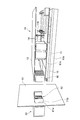
- the robot controller 1 includes a driver 10, a power supply unit 20, a central processing unit 50, and a housing 60 that accommodates these.
- the driver 10 is connected to the articulated robot 2 via the external cable 5 and drives the actuators of each joint of the articulated robot 2.
- the power supply unit 20 supplies power to the driver 10, the central processing unit 50, and the like.
- the central calculation unit 50 is a computer that calculates the drive amount of each actuator necessary for causing the articulated robot 2 to perform a desired operation.
- the housing 60 is a rectangular parallelepiped storage box made of a metal plate such as iron, stainless steel or aluminum alloy.
- an input switch such as a power switch 74 and various displays are provided on one side of the housing 60.
- front the surface on which the input switch and various indicators are provided
- back the opposite surface
- Front / Right / Left / Right means a direction in which the “front” side is the front side and the “back” side is the rear side.
- the power supply unit 20 is housed in the lower region Ab in the housing 60, the central processing unit 50 is housed in the upper region At in the housing 60, and the intermediate region Am between the lower region Ab and the upper region At.
- the driver 10 is accommodated.
- the lower region Ab and the intermediate region Am are partitioned by a partition wall (not shown).
- the casing 60 is equipped with devices for appropriately cooling the driver 10, the power supply unit 20, the central processing unit 50, and the like by outside air, such as a fan, a slit, and a heat exchanger. FIG. Is omitted.
- the driver 10 includes substrates 11 ⁇ / b> A and 11 ⁇ / b> B, a protection plate 12, and a heat dissipation plate 13.
- the substrate 11A is disposed horizontally in the housing 60.
- the substrate 11A is provided with a plurality of drive elements (not shown) that respectively drive a plurality of actuators.
- the plurality of driving elements are arranged in the horizontal direction below the substrate 11A.
- the driver 10 can drive a 9-axis actuator, and nine drive elements are provided on the substrate 11A correspondingly.
- the multi-joint robot 2 has a six-axis actuator
- six of the nine drive elements are allocated for driving the actuator of the multi-joint robot 2.
- the remaining three drive elements can be used for driving other actuators (hereinafter referred to as “external shaft actuators”).
- the external shaft actuator include an actuator of the tool 3 and an actuator of a workpiece transfer device.
- the substrate 11B is parallel to the substrate 11A and is fixed on the substrate 11A via the spacers 14.
- the substrate 11B is provided with a command circuit that outputs a command signal to each drive element of the substrate 11A.
- the protective plate 12 extends so as to cover the upper surfaces of the substrates 11A and 11B, and protects elements and wiring on the substrates 11A and 11B.
- the protection plate 12 is fixed on the substrate 11B via the spacer 14.
- the heat sink 13 is made of a metal material such as aluminum and is disposed under the substrate 11A.
- the heat radiating plate 13 spreads so as to cover the lower surface of the substrate 11A, and is fixed to the substrate 11A in close contact with each drive element of the substrate 11A.
- a plurality of fins 13 a that are parallel to each other are provided below the heat radiating plate 13.
- the plurality of fins 13a respectively extend along the front-rear direction and protrude downward, and enter the lower region Ab. Heat generated by each drive element of the substrate 11A is transferred to the heat radiating plate 13 and released. Therefore, each drive element is efficiently cooled.
- the back plate 61 that forms the back surface of the housing 60 is provided with a multi-axis receptacle CN1 and three single-axis receptacles CN2.
- the multi-axis receptacle CN1 is a connector for connecting all the actuators of the articulated robot 2.
- the single axis receptacle CN2 is a connector for connecting an external axis actuator.
- the single-axis receptacle CN2 has a sensor connector 72 and a power connector 73.
- the sensor connector 72 and the power connector 73 are connected to a driving element or the like on the substrate 11A via a cable (not shown) in the housing 60.
- the multi-axis receptacle CN1 includes a connector main body 15, a cover member 16, an opening 61a, and a receptacle shell (connector shell) 71. That is, the robot controller 1 includes a connector main body 15, a cover member 16, an opening 61 a, and a receptacle shell 71.
- the connector body 15 is provided on the substrate 11A. More specifically, the connector main body 15 is fixed to the rear side on the board 11A and protrudes rearward from the rear edge 11a of the board 11A.
- the connector main body 15 is made of a resin and has a rectangular parallelepiped shape opened rearward.
- the inside of the connector main body 15 is partitioned into a plurality of cells 17 along the front-rear direction.
- the cell 17A on the outer peripheral side of the connector body 15 accommodates a power terminal Tp for supplying power.
- a signal terminal Ts for signal transmission is accommodated in the cell 17B surrounded by the cell 17A (see FIG. 5). Although detailed illustration is omitted, the power terminal Tp and the signal terminal Ts are connected to a driving element or the like by wiring on the substrate 11A.
- the cover member 16 is a metal thin plate such as copper or aluminum, and has an inverted U-shaped cross-sectional shape to cover the upper surface and the left and right side surfaces of the connector body 15. That is, the cover member 16 is provided so as to cover at least a part of the outer periphery of the connector main body 15. The rear edge 16d of the cover member 16 projects rearward from the rear end face 15a of the connector body 15 (see FIG. 4).
- the left and right lower end portions of the cover member 16 are provided with leg portions 16a protruding downward from the substrate 11A, and the lower end portion of the leg portion 16a is provided with a connecting piece 16b projecting outward in the left-right direction.
- the heat sink 13 protrudes rearward from the rear edge 11 a of the substrate 11 ⁇ / b> A, and the connection piece 16 b is in contact with the upper surface of the heat sink 13.
- a fixing hole 16c is formed in the connection piece 16b.
- a fixing screw (not shown) is inserted into the fixing hole 16c. By fixing this screw to the heat sink 13, the connection piece 16 b is fixed to the heat sink 13.
- the opening 61a is provided in the back plate 61 at a position corresponding to the connector body 15, and exposes the connector body 15 to the outside.
- the opening 61 a has a rectangular shape corresponding to the back surface shape of the connector main body 15.
- the receptacle shell 71 has a holding portion 71A and a shell main body 71B, and is attached to the peripheral portion of the opening 61a.
- the receptacle shell 71 is preferably made of metal in order to suppress the temperature rise of the connector main body 15 to be described later.
- the holding portion 71 ⁇ / b> A is a plate-like body parallel to the back plate 61 and is attached to the outer surface of the back plate 61.
- the holding portion 71A is formed with a recess 71a that opens rearward.
- a pair of guide protrusions 71b are provided on the left and right portions of the bottom of the recess 71a.
- the guide protrusion 71b has a plate shape that extends rearward and along the vertical direction.
- the guide protrusion 71b may have a rod shape protruding rearward.
- An opening 71c corresponding to the opening 61a is formed between the guide protrusions 71b.
- a pair of mounting holes 71d are formed in the holding portion 71A on the left and right sides of the recess 71a.
- the attachment hole 71d has a vertically long elliptical shape.
- a screw is inserted into the mounting hole 71d.
- the holding portion 71 ⁇ / b> A is attached to the back plate 61.
- the screw is fixed to the back plate 61 in a state where the holding portion 71A is not completely tightened.
- the receptacle shell 71 is attached to the back plate 61 with a backlash along the back surface of the housing 60 with respect to the opening 61a.
- the mounting hole 71d has a vertically long elliptical shape, and therefore the backlash width in the up and down direction is larger than the backlash width in the left and right direction.
- the shell body 71B protrudes forward from the upper edge portion and the left and right side edge portions of the opening 71c, and exhibits an inverted U-shaped cross-sectional shape.
- a guide surface 71e is formed on the front portion of the inner peripheral surface of the shell main body 71B so as to spread outward as it goes forward (board 11A side) (see FIG. 6).
- the shell body 71B is passed through the opening 61a from the outside of the back plate 61, and the holding portion 71A is attached to the back plate 61, whereby the receptacle shell 71 is provided on the peripheral edge of the opening 61a.
- the shell main body 71B is located in the housing 60 and surrounds the upper surface and the left and right side surfaces of the connector main body 15. Since the cover member 16 is provided on the outer periphery of the connector main body 15, the cover member 16 is interposed between the connector main body 15 and the shell main body 71B.
- the plug 80 provided at the end of the external cable 5 is connected to the multi-axis receptacle CN1.
- the plug 80 includes a connector main body 82, a plug shell 81, and a plug cover 83.
- the connector body 82 has a plurality of cylindrical portions 84 that are respectively inserted into the plurality of cells 17 of the connector body 15. Each cylindrical portion 84 accommodates a terminal (not shown) connected to the external cable 5.
- the terminal of the cylindrical portion 84A disposed on the outer peripheral side of the connector main body 82 is connected to the power terminal Tp of the cell 17A.
- the terminal of the cylindrical portion 84B surrounded by the cylindrical portion 84A is connected to the signal terminal Ts of the cell 17B.
- the plug shell 81 is a container that is provided on the outer periphery of the external cable 5 and opens forward, and accommodates the connector main body 82.
- the plug cover 83 is a lid member that partially closes the opening of the plug shell 81 and holds the connector body 82 in the plug shell 81.
- a rectangular opening 83a for exposing the connector main body 82 to the front is formed in the center of the plug cover 83.
- a convex portion 83b protruding forward is formed over the entire circumference.
- the convex portion 83b fits into the concave portion 71a of the holding portion 71A. By this fitting, the holding portion 71 ⁇ / b> A holds the plug 80.
- Guide openings 83c for receiving the guide protrusions 71b are formed in the left and right portions of the convex portion 83b.
- the guide opening 83c has a slit shape corresponding to the guide protrusion 71b having a plate shape.
- the guide opening 83c has a hole shape.
- mounting holes 83d are formed.
- a screw is inserted into the mounting hole 83d.
- the plug cover 83 is attached to the plug shell 81.
- the screw is fixed to the plug shell 81 without completely tightening the plug cover 83.
- the plug cover 83 is attached to the plug shell 81 with a backlash along the front end surface of the plug shell 81.
- the plug 80 of the external cable 5 is connected to the connector main body. 15 can be directly connected. For this reason, it is not necessary to interpose a cable between the plug 80 and the board 11 ⁇ / b> A in the housing 60. Therefore, the cables inside the housing 60 can be reduced.
- a receptacle shell 71 is provided at the peripheral edge of the opening 61a, and the connector main body 15 is surrounded by the receptacle shell 71. Further, a metal cover member 16 is interposed between the connector main body 15 and the receptacle shell 71.
- the heat generated in the connector main body 15 can be dispersed in the housing 60 and the temperature rise of the connector main body 15 can be suppressed. If the receptacle shell 71 is also made of metal, the heat generated in the connector body 15 can be more efficiently distributed to the housing 60. In this way, suppressing the temperature rise of the connector main body 15 greatly contributes to the realization of a configuration in which the plug 80 is directly connected to the connector main body 15.
- the connector body 15 has a plurality of power terminals Tp and a plurality of signal terminals Ts, and the plurality of power terminals Tp are arranged on the outer peripheral side of the connector body 15.
- the power terminal Tp tends to generate heat more easily than the signal terminal Ts. For this reason, by arranging the power terminal Tp on the outer peripheral side of the connector main body 15 and bringing it close to the cover member 16 and the receptacle shell 71, the heat generated in the connector main body 15 can be more efficiently dispersed in the housing 60. Therefore, the temperature rise of the connector main body 15 can be suppressed more reliably.
- the partition 18 made from metals, such as copper and aluminum, between the cell 17A which accommodates the electric power terminal Tp, and the cell 17B which accommodates the signal terminal Ts (refer FIG. 7). Due to the shielding effect of the partition wall 18, noise propagation from the power terminal Tp to the signal terminal Ts is suppressed, so that it is easy to collect many terminals in the connector body 15.
- the edge 16d on the rear side (opening 61a side) of the cover member 16 protrudes from the rear end surface (end surface on the opening 61a side) 15a of the connector body 15.
- the connector body 15 is inserted from the inside of the housing 60 toward the shell body 71B of the receptacle shell 71, that is, from the front to the back.
- the edge 16d protrudes from the end surface 15a, the rear end portion of the connector body 15 can be protected when the connector body 15 is inserted into the receptacle shell 71.
- a guide surface 71e is formed on the front portion (portion on the substrate 11A side) of the inner peripheral surface of the shell body 71B. For this reason, the connector main body 15 can be smoothly inserted into the shell main body 71B.
- a guide surface 16e may be formed on the rear portion (portion on the opening 61a side) of the outer peripheral surface of the cover member 16 so as to shrink toward the rear side (inward). (See FIG. 8). Also in this case, the connector main body 15 can be smoothly inserted into the shell main body 71B. Both the guide surface 71e and the guide surface 16e may be formed.
- the receptacle shell 71 is attached to the housing 60 with a backlash along the back surface of the housing 60 with respect to the opening 61a. For this reason, the position of the receptacle shell 71 can be adapted to variations in the position of the connector body 15. Thereby, the connector main body 15 can be more smoothly inserted into the receptacle shell 71.
- the mounting hole 71d has a vertically long elliptical shape, so that the vertical rattling width is larger than the lateral rattling width. For this reason, it is easy to adapt the position of the receptacle shell 71 to variations in the position of the connector body 15 in the thickness direction of the board 11A.
- the plug cover 83 is attached to the plug shell 81 with a backlash. For this reason, even if the convex part 83b is fitted in the concave part 71a, the connector main body 82 is held with a backlash relative to the opening 83a. Thereby, the position of the connector main body 82 can be adapted to the variation in the position of the connector main body 15. Therefore, the cylindrical portion 84 can be inserted into the cell 17 more smoothly.
- the receptacle shell 71 has a holding portion 71A for holding the plug 80.
- the connector main body 15 is used as a connector for connecting the plug 80
- the driver 10 is pulled out in the front direction and taken out from the housing 60 for replacement, there is no connection destination of the plug 80. For this reason, it is necessary to remove the plug 80 from the robot controller 1 in order to replace the driver 10, and the replacement work of the driver 10 becomes complicated.
- the receptacle shell 71 with the holding portion 71A for holding the plug 80, the driver 10 can be replaced while the plug 80 is attached to the robot controller 1 (see FIG. 9). That is, it is possible to achieve both reduction of the cable inside the housing 60 and simplification of the replacement work of the driver 10.
- connection portion of the external cable 5 in the robot controller 1 is arranged in the fence 6, the effectiveness of being able to replace the driver 10 without removing the plug 80 from the robot controller 1 becomes remarkable.
- a lock mechanism for fixing the plug 80 to the holding portion 71A with a screw or the like may be further provided in order to more reliably prevent the plug 80 from falling off when the driver 10 is replaced.
- the cover member 16 is fixed to the heat sink 13. Thereby, the temperature rise of the connector main body 15 can be suppressed more reliably.
- the cover member 16 may cover the entire circumference of the connector body 15 or may partially cover only one surface of the connector body 15.
- the receptacle shell 71 may surround the entire circumference of the connector body 15.
- the multi-axis receptacle CN1 for the actuator of the articulated robot 2 and the single-axis receptacle CN2 for the external axis actuator need not necessarily be separated.
- a terminal for an external shaft actuator may be included in the receptacle CN1.
- the number of actuators controlled by the driver 10 is not limited to nine axes, and may be a single axis.
- the control target may be anything as long as it is electrically controlled, and is not limited to the articulated robot 2.
- Examples of the control target include a machine tool and a transport device.
- the present invention can be used for a control device attached to an electrically controlled device.
- SYMBOLS 1 Robot controller (control apparatus), 10 ... Driver, 11A ... Board
Landscapes
- Engineering & Computer Science (AREA)
- Microelectronics & Electronic Packaging (AREA)
- Shielding Devices Or Components To Electric Or Magnetic Fields (AREA)
- Mounting Of Printed Circuit Boards And The Like (AREA)
- Details Of Connecting Devices For Male And Female Coupling (AREA)
- Connector Housings Or Holding Contact Members (AREA)
- Manipulator (AREA)
Abstract
La présente invention concerne un dispositif de commande, comprenant : un circuit d'excitation comportant un substrat ; un logement servant à loger le circuit d'excitation ; un corps de connecteur disposé sur le substrat ; une ouverture servant à exposer le corps de connecteur à l'extérieur, et disposée dans le logement ; une coque de connecteur disposée dans la section de bordure périphérique de l'ouverture de façon à entourer le corps de connecteur ; et un élément de couverture métallique interposé entre le corps de connecteur et la coque de connecteur, et disposé de façon à recouvrir au moins une partie de la périphérie externe du corps de connecteur.
Priority Applications (2)
| Application Number | Priority Date | Filing Date | Title |
|---|---|---|---|
| JP2015519594A JP6202095B2 (ja) | 2013-05-31 | 2013-05-31 | 制御装置 |
| PCT/JP2013/065283 WO2014192158A1 (fr) | 2013-05-31 | 2013-05-31 | Dispositif de commande |
Applications Claiming Priority (1)
| Application Number | Priority Date | Filing Date | Title |
|---|---|---|---|
| PCT/JP2013/065283 WO2014192158A1 (fr) | 2013-05-31 | 2013-05-31 | Dispositif de commande |
Publications (1)
| Publication Number | Publication Date |
|---|---|
| WO2014192158A1 true WO2014192158A1 (fr) | 2014-12-04 |
Family
ID=51988226
Family Applications (1)
| Application Number | Title | Priority Date | Filing Date |
|---|---|---|---|
| PCT/JP2013/065283 Ceased WO2014192158A1 (fr) | 2013-05-31 | 2013-05-31 | Dispositif de commande |
Country Status (2)
| Country | Link |
|---|---|
| JP (1) | JP6202095B2 (fr) |
| WO (1) | WO2014192158A1 (fr) |
Citations (4)
| Publication number | Priority date | Publication date | Assignee | Title |
|---|---|---|---|---|
| JPS59195684U (ja) * | 1983-06-15 | 1984-12-26 | 日本電気ホームエレクトロニクス株式会社 | カプラ取付構体 |
| JPH01158678U (fr) * | 1988-04-20 | 1989-11-01 | ||
| JP2000260528A (ja) * | 1998-10-19 | 2000-09-22 | Molex Inc | シールド電気コネクタ |
| JP2005285590A (ja) * | 2004-03-30 | 2005-10-13 | Japan Aviation Electronics Industry Ltd | Emi対策型コネクタ |
-
2013
- 2013-05-31 JP JP2015519594A patent/JP6202095B2/ja active Active
- 2013-05-31 WO PCT/JP2013/065283 patent/WO2014192158A1/fr not_active Ceased
Patent Citations (4)
| Publication number | Priority date | Publication date | Assignee | Title |
|---|---|---|---|---|
| JPS59195684U (ja) * | 1983-06-15 | 1984-12-26 | 日本電気ホームエレクトロニクス株式会社 | カプラ取付構体 |
| JPH01158678U (fr) * | 1988-04-20 | 1989-11-01 | ||
| JP2000260528A (ja) * | 1998-10-19 | 2000-09-22 | Molex Inc | シールド電気コネクタ |
| JP2005285590A (ja) * | 2004-03-30 | 2005-10-13 | Japan Aviation Electronics Industry Ltd | Emi対策型コネクタ |
Also Published As
| Publication number | Publication date |
|---|---|
| JP6202095B2 (ja) | 2017-09-27 |
| JPWO2014192158A1 (ja) | 2017-02-23 |
Similar Documents
| Publication | Publication Date | Title |
|---|---|---|
| JP6998115B2 (ja) | ロボットコントローラ | |
| US20130119760A1 (en) | Electric vehicular power controller support structure and electric vehicle | |
| JP6224042B2 (ja) | 電気接続箱およびワイヤハーネス | |
| JP7340015B2 (ja) | ロボット用制御装置 | |
| JP6673546B2 (ja) | コントローラ組立体 | |
| CN107443421B (zh) | 电机单元以及机器人 | |
| JP2015136780A (ja) | コントローラ | |
| JP7470732B2 (ja) | 電子機器 | |
| JP4958988B2 (ja) | 電動圧縮機 | |
| CN106976066A (zh) | 机器人以及机器人系统 | |
| JP2013046506A (ja) | モータモジュールユニットとアクチュエータ | |
| JP6202095B2 (ja) | 制御装置 | |
| JP7309213B2 (ja) | 冷却デバイスを備えた溶接電流源 | |
| JP2019022293A (ja) | 電源装置 | |
| JP2021065016A (ja) | 制御装置およびモータ装置 | |
| JP5292524B1 (ja) | 電気自動車のパワーコントロールユニット | |
| JP5593296B2 (ja) | 制御装置 | |
| JP6641764B2 (ja) | 電池パック | |
| CN103379805A (zh) | 电子设备 | |
| JP7192004B2 (ja) | ロボットコントローラ | |
| JP7338313B2 (ja) | 車両用バッテリパック | |
| WO2016043204A1 (fr) | Boîte de connexion électrique | |
| JP2012253096A (ja) | 電子機器 | |
| JP7169085B2 (ja) | レーザ装置 | |
| JP7734019B2 (ja) | コントローラ |
Legal Events
| Date | Code | Title | Description |
|---|---|---|---|
| 121 | Ep: the epo has been informed by wipo that ep was designated in this application |
Ref document number: 13885655 Country of ref document: EP Kind code of ref document: A1 |
|
| ENP | Entry into the national phase |
Ref document number: 2015519594 Country of ref document: JP Kind code of ref document: A |
|
| NENP | Non-entry into the national phase |
Ref country code: DE |
|
| 122 | Ep: pct application non-entry in european phase |
Ref document number: 13885655 Country of ref document: EP Kind code of ref document: A1 |