WO2014192259A1 - Dispositif de commande de réseau, procédé de commande de réseau, programme associé et système de communication - Google Patents
Dispositif de commande de réseau, procédé de commande de réseau, programme associé et système de communication Download PDFInfo
- Publication number
- WO2014192259A1 WO2014192259A1 PCT/JP2014/002685 JP2014002685W WO2014192259A1 WO 2014192259 A1 WO2014192259 A1 WO 2014192259A1 JP 2014002685 W JP2014002685 W JP 2014002685W WO 2014192259 A1 WO2014192259 A1 WO 2014192259A1
- Authority
- WO
- WIPO (PCT)
- Prior art keywords
- network
- information processing
- resource
- communication data
- control device
- Prior art date
- Legal status (The legal status is an assumption and is not a legal conclusion. Google has not performed a legal analysis and makes no representation as to the accuracy of the status listed.)
- Ceased
Links
Images


Classifications
-
- H—ELECTRICITY
- H04—ELECTRIC COMMUNICATION TECHNIQUE
- H04L—TRANSMISSION OF DIGITAL INFORMATION, e.g. TELEGRAPHIC COMMUNICATION
- H04L67/00—Network arrangements or protocols for supporting network services or applications
- H04L67/34—Network arrangements or protocols for supporting network services or applications involving the movement of software or configuration parameters
-
- H—ELECTRICITY
- H04—ELECTRIC COMMUNICATION TECHNIQUE
- H04L—TRANSMISSION OF DIGITAL INFORMATION, e.g. TELEGRAPHIC COMMUNICATION
- H04L12/00—Data switching networks
- H04L12/64—Hybrid switching systems
- H04L12/6418—Hybrid transport
-
- H—ELECTRICITY
- H04—ELECTRIC COMMUNICATION TECHNIQUE
- H04L—TRANSMISSION OF DIGITAL INFORMATION, e.g. TELEGRAPHIC COMMUNICATION
- H04L41/00—Arrangements for maintenance, administration or management of data switching networks, e.g. of packet switching networks
- H04L41/08—Configuration management of networks or network elements
- H04L41/0803—Configuration setting
- H04L41/0813—Configuration setting characterised by the conditions triggering a change of settings
- H04L41/0816—Configuration setting characterised by the conditions triggering a change of settings the condition being an adaptation, e.g. in response to network events
-
- H—ELECTRICITY
- H04—ELECTRIC COMMUNICATION TECHNIQUE
- H04L—TRANSMISSION OF DIGITAL INFORMATION, e.g. TELEGRAPHIC COMMUNICATION
- H04L41/00—Arrangements for maintenance, administration or management of data switching networks, e.g. of packet switching networks
- H04L41/20—Network management software packages
Definitions
- the present invention relates to a network function virtualization technology in a communication system.
- the current communication system uses a dedicated appliance that is a hardware device for each network function in order to perform various network functions. Since such a dedicated appliance is required for the construction of the communication system, when a new network service is started, the network operator is forced to introduce a new dedicated appliance. In order to introduce a dedicated appliance, the network operator pays a great deal of cost such as the purchase cost and installation space of the dedicated appliance.
- the network operator since the life cycle of the dedicated appliance is becoming shorter in recent years, the network operator has a problem that the life cycle of the appliance ends without obtaining sufficient profit from the installed dedicated appliance.
- Patent Document 1 discloses an example of virtualization technology.
- the virtualization device starts a virtual machine on a computer resource, and the user terminal receives a service from the virtual machine.
- Patent Document 2 discloses a technology for constructing a virtual appliance having a function of a hardware device used for an information service.
- JP 2011-34403 A WO2009 / 098909
- Patent Documents 1 and 2 construct a web server, an application server, and the like arranged at a communication end point (that is, a communication start point or end point) using a virtualization technology.
- Patent Documents 1 and 2 do not disclose a technique for controlling a network communication path between end points.
- a dedicated appliance for a communication system is often arranged on a network communication path, and therefore, it is assumed that a virtual appliance is also arranged on a network communication path. Therefore, the virtual appliance may not be used efficiently unless the network communication path is controlled according to the arrangement of the virtual appliance.
- Patent Documents 1 and 2 do not disclose a technology for controlling a communication path, the technologies of Patent Documents 1 and 2 realize efficient use of a virtual appliance corresponding to a dedicated appliance of a communication system. It ’s difficult.
- An object of the present invention is to construct a dedicated appliance for a communication network by software and realize efficient use of the constructed virtual appliance.
- the network control device of the present invention is a network control device that constructs the function of a hardware device used in a communication network by software, and the software that can execute the function of the hardware device is arranged in an information processing resource And first means for identifying communication data to be processed by the arranged software and instructing the network resource to transfer the identified communication data to the information processing resource. .
- the network control method of the present invention is a network control method for constructing functions of hardware devices used in a communication network by software, and arranging the software capable of executing the functions of the hardware devices in an information processing resource And identifying communication data to be processed by the arranged software and instructing the network resource to transfer the identified communication data to the information processing resource.
- the program of the present invention includes a process of placing the software capable of executing the function of the hardware device in an information processing resource in a network control device that constructs the function of the hardware device used in the communication network by software, The communication data to be processed by the arranged software is identified, and a process for instructing the network resource to transfer the identified communication data to the information processing resource is executed.
- the system of the present invention is a system in which functions of hardware devices used in a communication network can be constructed by software, and the software capable of executing functions of the hardware devices is arranged in an information processing resource. And second means for instructing network resources to identify communication data to be processed by the arranged software and to transfer the identified communication data to the information processing resource.
- the network control device of the present invention is a network control device that constructs the functions of hardware devices used in a communication network by software, and the software that can execute the functions of the hardware devices in a lower-level control device, A first means for instructing placement on an information processing resource, and network operation rules for identifying communication data to be processed by the placed software and transferring the identified communication data to the information processing resource And a second means for instructing the subordinate control apparatus to notify the resource.
- the communication system of the present invention includes a data transfer device for transferring communication data, an information processing device in which software capable of executing a function of a gateway device for relaying communication between communication networks is arranged, and processing by the arranged software
- a control device that instructs the data transfer device to transfer the communication data to be transmitted to the information processing device.
- the network control device of the present invention controls a communication system including a data transfer device that transfers communication data and an information processing device in which software capable of executing a function of a gateway device that relays communication between communication networks is arranged.
- a network control device comprising control means for instructing the data transfer device to transfer communication data processed by the arranged software to the information processing device.
- a dedicated appliance for a communication network can be constructed by software, and a communication service that efficiently uses the constructed virtual appliance can be provided.
- FIG. 1 is a schematic block diagram showing an example of a network control apparatus according to Embodiment 1 of the present invention.
- FIG. 2 is a schematic diagram for explaining an operation example of the network control apparatus according to the first embodiment.
- FIG. 3 is a sequence diagram illustrating an operation example of the network control apparatus according to the first embodiment.
- FIG. 4 is a schematic diagram for explaining an operation example of the communication system according to the second embodiment of the present invention.
- FIG. 5 is a block diagram showing an example of a network control apparatus according to Embodiment 3 of the present invention.
- FIG. 6 is a functional block configuration diagram illustrating an example of the SW repository according to the third embodiment.
- FIG. 7 is a sequence diagram illustrating an operation example of the network control apparatus according to the third embodiment.
- FIG. 1 is a schematic block diagram showing an example of a network control apparatus according to Embodiment 1 of the present invention.
- FIG. 2 is a schematic diagram for explaining an operation example of the network control apparatus according to the first embodiment.
- FIG. 8 is a block diagram illustrating a schematic configuration of a communication system according to the third embodiment.
- FIG. 9 is a schematic diagram for explaining an operation example of the communication system according to the third embodiment.
- FIG. 10 is a schematic configuration diagram illustrating an example of a communication system according to the third embodiment.
- FIG. 11 is a format diagram schematically showing the configuration of entries stored in the flow table in FIG.
- FIG. 12 is a sequence diagram showing an operation example of the network control apparatus according to the fourth embodiment of the present invention.
- FIG. 13 is a system configuration diagram showing an example of a communication system according to Embodiment 5 of the present invention.
- FIG. 14 is a schematic configuration diagram illustrating an example of information processing resources according to the fifth embodiment.
- FIG. 15 is a sequence diagram illustrating an operation example of the communication system according to the fifth embodiment.
- FIG. 16 is a schematic diagram for explaining an operation example of the communication system according to the fifth embodiment.
- FIG. 17 is a schematic diagram for explaining an operation example of the communication system according to the fifth embodiment.
- FIG. 18 is a system configuration diagram showing an example of a communication system according to Embodiment 6 of the present invention.
- FIG. 19 is a block diagram illustrating an example of a network control apparatus according to the sixth embodiment.
- FIG. 20 is a system configuration diagram for explaining an operation example of the communication system according to the sixth embodiment.
- FIG. 21 is a block diagram illustrating an example of an optical communication node according to the sixth embodiment.
- FIG. 22 is a network configuration diagram showing an example of a communication system according to Embodiment 7 of the present invention.
- FIG. 23 is a network configuration diagram illustrating another example of the communication system according to the seventh embodiment.
- FIG. 24 is a schematic diagram illustrating an example of a routing table in the seventh embodiment.
- FIG. 25 is a schematic diagram illustrating another example of the routing table in the seventh embodiment.
- FIG. 26 is a schematic network configuration diagram for explaining a first operation example of the communication system according to the seventh embodiment.
- FIG. 27 is a schematic network configuration diagram for explaining a second operation example of the communication system according to the seventh embodiment.
- FIG. 28 is a sequence diagram illustrating an operation example of the communication system according to the seventh embodiment.
- FIG. 29 is a sequence diagram illustrating an operation example of the communication system according to the seventh embodiment.
- FIG. 30 is a system configuration diagram showing an example of a communication system according to Embodiment 8 of the present invention.
- FIG. 31 is a system configuration diagram showing another example of the communication system according to the eighth embodiment.
- the present invention provides a network control device capable of constructing the function of a dedicated appliance of a communication system using a virtualization technology.
- the network control device can control a communication path in the network according to the construction of a virtual appliance (software) corresponding to the dedicated appliance. For example, according to the construction of the virtual appliance, the network control device can control the communication path of the network so that the communication data passes through the virtual appliance.
- the network control device of the present invention can perform path control for efficiently using the virtual appliance according to the construction of the virtual appliance.
- the operator of the communication system can construct the network function that has been executed by the dedicated appliance so far by using a general-purpose device (eg, Standard Server And Networking device etc). Can do. Therefore, the operator of the communication system can greatly reduce the cost required for newly starting a network service.
- a general-purpose device eg, Standard Server And Networking device etc.
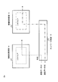
- FIG. 1 illustrates a configuration example of the network control device 1 according to the first embodiment.
- the network control device 1 can virtually construct the function executed by the dedicated appliance using the network resource 13 and the information processing resource 14.
- the network resource 13 and the information processing resource 14 are, for example, standard general-purpose devices.
- the network resource 13 and the information processing resource 14 are resource pools in which, for example, general-purpose processors, general-purpose servers, general-purpose network switches, storage devices, general-purpose routers, and the like are stored.
- the network resource 13 and the information processing resource 14 may be configured by software instead of hardware devices.
- the network resource 13 may be a virtual switch configured by software.
- the information processing resource 14 may be a virtual machine, for example.
- the network control device 1 includes a network resource control unit 11 and an information processing resource control unit 12. Each function of the network control device 1 can be configured by either hardware or software program.
- the network resource control unit 11 and the information processing resource control unit 12 may be mounted on different devices.
- the network control device 1 is divided into a device that controls the network resource 13 and a device that controls the information processing resource 14.
- the information processing resource control unit 12 places software for executing a network function corresponding to the dedicated appliance in the information processing resource 14.
- deployment includes installing software in the information processing resource 14.
- the network function is a function corresponding to various dedicated appliances in a mobile network, for example.
- Dedicated appliances in mobile networks are, for example, MME (Mobility Management Entity), S-GW (Serving-Gateway), P-GW (PacketData Network-Gateway), Large-scale NAT (LSN: Large Scale Network NC). Radio Network Controller), eNodeB, and the like.
- BRAS Broadband Remote Access Server
- CDN Server Contents Delivery Network Server
- SBC Session Board Controller
- the network resource control unit 11 controls the communication path in order to use the software arranged in the information processing resource 14 by controlling the network resource 13. For example, the network resource control unit 11 controls the communication path by instructing the network resource 13 to perform the operation determined by the network resource control unit 11.
- the information processing resource control unit 12 places software capable of executing the functions of the dedicated appliance in the information processing resource 14.
- software may be indicated as “virtual appliance”.
- the network resource control unit 11 identifies communication data processed by the arranged software according to the arrangement of the software, and instructs the network resource 13 to transfer the identified communication data to the information processing resource 14. .
- the network resource 13 identifies whether the received communication data is data to be processed by software arranged in the information processing resource 14 according to an instruction from the network resource control unit 11.
- the network resource 13 identifies communication data by referring to information included in the communication data, for example.
- the communication data is processed by software arranged in the information processing resource 14 and transferred to the network.
- the network resource control unit 11 determines an identification condition for identifying communication data processed by software arranged in the information processing resource 14, for example. For example, the network resource control unit 11 determines the identification condition according to the function type of the dedicated appliance (the type of function executed by the ee software). By determining the identification condition based on the function type, the network resource control unit 11 can execute path control suitable for the function type of the dedicated appliance. The network resource 13 identifies the communication data according to the notified identification condition, and transfers the communication data meeting the condition to the information processing resource 14.
- the network resource control unit 11 transfers communication data that is not a target of processing by the arranged software to the other network resource 13 without transferring the communication data to the information processing resource 14 on which the software is arranged.
- FIG. 3 is a sequence diagram illustrating an operation example of the first embodiment.
- the sequence diagram of FIG. 3 is an example, and the operation of the present invention is not limited to the sequence diagram of FIG.
- the operator requests the information processing resource control unit 12 to construct a virtual appliance (operation S1).
- the information processing resource control unit 12 may autonomously construct a virtual appliance without depending on an instruction from the operator.
- the information processing resource control unit 12 arranges software capable of executing the network function of the dedicated appliance for the information processing resource 14 (operation S2).
- the operator requests the network resource control unit 11 to control the network resource 13 (operation S3).
- the network resource control unit 11 may autonomously control the network resource 13 without depending on an instruction from the operator.
- the network resource control unit 11 notifies the operation rule to the network resource 13 (operation S4).
- the operation rule includes the identification condition described above. For example, communication data to be processed by the arranged software is identified, and an operation rule is set in the network resource 13 instructing to transfer the identified communication data to the information processing resource 14 in which the software is arranged.
- the network control device 1 according to the first embodiment can perform path control for efficiently using the virtual appliance according to the construction of the virtual appliance.
- the operator of the communication system can construct the network function that has been executed by the dedicated appliance so far by a general-purpose device. Therefore, the operator of the communication system can greatly reduce the cost required for newly starting a network service.
- the network resource control unit 11 of the network control apparatus can instruct the network resource 13 to select a transfer destination of communication data from a plurality of information processing resources 14. For example, when the same type of software is arranged in a plurality of information processing resources 14, the network resource control unit 11 can change the information processing resource 14 as a transfer destination according to communication data. Therefore, the network resource control unit 11 can execute various controls for efficiently using the virtual appliance constructed by software, such as load distribution of the information processing resource 14.
- FIG. 4 shows an operation example of the second embodiment.
- the operation shown in FIG. 4 is an example, and the present invention is not limited to FIG.
- the information processing resource control unit 12 arranges software capable of executing the function of the dedicated appliance in each of the plurality of information processing resources 14. For example, each software has the same function.
- the network resource control unit 11 notifies the network resource 13 of selection conditions for selecting a transfer destination of communication data from a plurality of information processing resources 14. For example, the network resource control unit 11 determines a selection condition for selecting a transfer destination of communication data from a plurality of information processing resources 14 in which software is arranged, and notifies the network resource 13 of the selection condition.
- the network resource control unit 11 can determine the selection condition so that the loads of the plurality of information processing resources 14 are distributed. Further, the network resource control unit 11 determines a selection condition so as to transfer communication data requiring high quality to the information processing resource 14 having a low load based on QoS information associated with the communication data. Also good. Note that the above-described condition determination methods are examples, and the present invention is not limited to these condition determination methods.
- Embodiment 3 hereinafter, in the third embodiment of the present invention, differences from the other embodiments are mainly described, and the contents already described in the other embodiments are omitted.
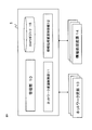
- the network control device 1 includes a management unit 10 and a SW (Software) repository 15.
- FIG. 5 is an exemplification, and the network control device 1 of the present invention is not limited to the configuration example of FIG.
- the management unit 10 secures network resources 13 and information processing resources 14 that are necessary for constructing a network function corresponding to the dedicated appliance. For example, the management unit 10 calculates the required resource amount of the network resource 13 and the information processing resource 14 based on performance values required for the network function. The management unit 10 allocates the calculated amount of resources to the network function. The management unit 10 may request the network resource control unit 11 and the information processing resource control unit 12 to allocate the network resource 13 and the information processing resource 14 respectively.
- the management unit 10 manages information related to the network resource 13 and the information processing resource 14 (for example, the deployment status of the information processing resource 14 and the topology information of the network resource 13).
- the topology information of the network resource 13 is, for example, a connection form of a network configured with the network resource 13.
- the management unit 10 refers to the information and allocates resources to a network function (that is, a virtual appliance) that is virtually constructed.
- the information processing resource control unit 12 selects a software application corresponding to the network function from the SW repository 15.
- the information processing resource control unit 12 selects an application from the network function module 150 of the SW repository 15 having the configuration illustrated in FIG.
- the information processing resource control unit 12 installs the selected application in the information processing resource 14.
- the information processing resource control unit 12 starts a virtual machine on the information processing resource 14 and installs the selected application on the virtual machine.
- the network resource control unit 11 selects a control module for the network resource 13 from the SW repository 15. For example, the network resource control unit 11 selects a module corresponding to the application selected by the information processing resource control unit 12 from the NW control module 151 of the SW repository 15 illustrated in FIG.
- the selected NW control module 151 is a module for executing path control corresponding to the application selected by the information processing resource control unit 12.
- the NW control module 151 has a function for determining an operation rule to be notified to the network resource 13, for example.
- the NW control module 151 may have a function for determining the “identification condition” and “selection condition” described in the above embodiment. Note that these functions may differ depending on the network function of the dedicated appliance.
- the network resource control unit 11 controls the network resource 13 using the selected NW control module 151.
- the management unit 10 selects the network function module 150 and the NW control module 151 from the SW repository 15, and selects the selected module as the network resource control unit 11 and the information processing resource. You may transmit to the control part 12.
- the SW repository 15 is not limited to the configuration example of FIG.
- the NW control module 151 may be common to the plurality of network function modules 150.
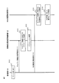
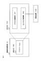
- FIG. 7 is a sequence diagram illustrating an operation example of the third embodiment.
- the sequence diagram of FIG. 7 is an example, and the operation of the present invention is not limited to FIG.
- the management unit 10 allocates the network resource 13 and the information processing resource 14 to the network function (operation S10).
- the management unit 10 may request the network resource control unit 11 and the information processing resource control unit 12 to allocate the network resource 13 and the information processing resource 14, respectively. In that case, the information processing resource control unit 12 and the network resource control unit 11 each allocate resources to the network function in response to the request.
- the operator for example, inputs parameters such as the target performance value of the newly started network function to the network control device 1 via the OSS / BSS (Operation Support System / Business Support System) 100 illustrated in FIG. Can do.
- the management unit 10 can allocate network resources 13 and information processing resources 14 based on parameters input from the OSS / BSS 100. For example, the management unit 10 calculates the resource amounts of the network resource 13 and the information processing resource 14 so as to satisfy a target performance value (for example, an arithmetic processing capability or a communication bandwidth) input by the operator.
- a target performance value for example, an arithmetic processing capability or a communication bandwidth
- the management unit 10 may request the network resource control unit 11 and the information processing resource control unit 12 to allocate the network resource 13 and the information processing resource 14, respectively. In that case, the information processing resource control unit 12 and the network resource control unit 11 each allocate resources to the network function in response to the request.
- the management unit 10 requests the information processing resource control unit 12 to arrange software corresponding to the network function (operation S11). For example, the management unit 10 notifies the information processing resource control unit 12 of the type of the network function, and requests the information processing resource 14 to place a module corresponding to the network function.
- the information processing resource control unit 12 selects an application corresponding to the network function from the SW repository 15 (operation S12). Instead of the information processing resource control unit 12, the management unit 10 may select an application and notify the information processing resource control unit 12 of the selected application.
- the information processing resource control unit 12 places the selected application on the information processing resource 14 (operation S13).
- the management unit 10 requests the network resource control unit 11 to control the network resource 13 (operation S14). For example, the management unit 10 notifies the network resource control unit 11 of the type of the network function, and requests to control the network resource 13 by selecting a module corresponding to the network function.
- the network resource control unit 11 selects the NW control module 151 corresponding to the network function from the SW repository 15 (operation S15). Instead of the operations S14 and S15, the management unit 10 may select the NW control module 151 and notify the network resource control unit 11 of the selected module. In this case, the management unit 10 requests the network resource control unit 11 to control the network resource 13 by the notified module.
- the network resource control unit 11 sets an operation rule for the network resource 13 using the selected NW control module 151 (operation S16).
- FIG. 9 to FIG. 11 are examples, and the control operation of the network resource 13 in the present invention is not limited to FIG. 9 to FIG. Also, the operations illustrated in FIGS. 9 to 11 can be applied to other embodiments (Embodiments 1 and 2 and later-described embodiments).
- the network resource 13 includes a Rule DB (Database) 130 and a communication processing unit 131, and executes communication processing according to the rules notified by the network resource control unit 11.
- Rule DB Database
- communication processing unit 131 executes communication processing according to the rules notified by the network resource control unit 11.
- the network resource control unit 11 sets a rule for the network resource 13 to execute communication processing corresponding to the network function in the Rule DB 130 of the network resource 13 by the NW control module 151.
- the NW control module 151 has a function for determining an operation rule to be notified to the network resource 13, and determines the “identification condition” and “selection condition” described in the above embodiment. Can have a function for.
- these functions may differ depending on the network function that the dedicated appliance has.
- the network control device 1 can virtually construct the network function executed by the dedicated appliance by the function of the NW control module 151 and the function of the application arranged in the information processing resource 14.
- the communication processing unit 131 refers to the Rule DB 130 and processes communication data.
- a technique called OpenFlow is applied will be described with reference to FIGS. 10 and 11.
- OpenFlow is a technology in which a controller centrally manages network devices (switches, etc.) and controls the operation of network devices. It recognizes communication as an end-to-end flow and can execute path control and the like on a per-flow basis.
- the network resource control unit 11 can also be realized by improving and applying OpenFlow.
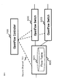
- FIG. 10 shows an overview of a communication system configured with OpenFlow.
- a flow is a series of communication packets having predetermined attributes (attributes identified based on a communication destination, a transmission source, and the like), for example.
- the OpenFlow switch 600 is a network switch that employs OpenFlow technology.
- the OpenFlow controller 700 is an information processing apparatus that controls the OpenFlow switch 600.
- the OpenFlow switch 600 communicates with the OpenFlow controller via a secure channel 701 set with the OpenFlow controller 700.
- the OpenFlow controller 700 sets the flow table 601 of the OpenFlow switch 600 via the secure channel 701.
- the secure channel 701 is a communication path on which measures for preventing eavesdropping or falsification of communication between the switch and the controller are taken.
- FIG. 11 shows a configuration example of each entry (flow entry) in the flow table 601.
- the flow entry includes a matching rule (Match Fields) for matching information (for example, destination IP address, VLAN ID, etc.) included in the packet received by the switch, and statistical information (Counters) that is statistical information for each packet flow.
- a matching rule Match Fields
- Counters statistical information
- An action Actions that defines a method of processing a packet that matches the matching rule.
- the OpenFlow switch 600 When the OpenFlow switch 600 receives a packet, the OpenFlow switch 600 refers to the flow table 601. The OpenFlow switch 600 searches for a flow entry that matches information included in the received packet. When an entry that matches the information included in the received packet is found, the OpenFlow switch 600 processes the received packet according to the processing method defined in the action field of the found entry.
- the processing method is defined, for example, as “transfer received packet from predetermined port”, “discard received packet”, or “rewrite part of received packet header and transfer from predetermined port” Is done.
- the OpenFlow switch 600 transfers the received packet to the OpenFlow controller 700 via the secure channel 701, for example.
- the OpenFlow switch 600 may transfer the received packet to the OpenFlow controller 700 when the action “inquiry to the controller” is defined in the flow entry that matches the information included in the received packet. Good.
- the OpenFlow switch 600 requests the controller to set a flow entry that defines the received packet processing method by transferring the received packet.
- the OpenFlow controller 700 determines a received packet processing method, and sets a flow entry including the determined processing method in the flow table 601. Thereafter, the OpenFlow switch 600 processes subsequent packets belonging to the same flow as the received packet according to the set flow entry.
- the NW control module 151 can program the operation of the network resource 13 in order to improve and apply the above-described OpenFlow and virtually construct the network function of the dedicated appliance.
- the network control device 1 notifies the network resource 13 of an operation rule according to a control policy corresponding to the virtual appliance. Notifying the operation rule is almost synonymous with “programming” the operation of the network resource 13. Therefore, generating a control policy for programming the operation of the network resource 13 each time the virtual appliance is started can be an excessive burden on the operator.
- the NW control module 151 for generating the operation rule to be notified to the network resource 13 is stored in the SW repository 15 in advance.
- the network control apparatus 1 can select and use the NW control module 151 corresponding to the virtual appliance from the repository. Therefore, the operator reduces the load for generating a control policy for programming the network resource 13 every time a new virtual appliance is started, and the operation efficiency is improved.
- Embodiment 4 According to the fourth embodiment of the present invention, the network control device 1 monitors the operation status of the communication network, and executes resource enhancement or reduction according to the monitoring result. With the network control device 1 according to the fourth embodiment, the operator of the communication system can operate the system autonomously, and the operation efficiency of the operator is improved.
- FIG. 12 is a sequence diagram illustrating an operation example of the fourth embodiment.
- the sequence diagram of FIG. 12 is an example, and the operation of the present invention is not limited to the sequence diagram of FIG.
- the network control device 1 monitors the operation status of the communication network (operation S20). For example, the network control device 1 monitors the operation status of the network resource 13 and the information processing resource 14 that virtually construct the network function.
- the network resource control unit 11 and the information processing resource control unit 12 of the network control device 1 may monitor the operation status of the network resource 13 and the information processing resource 14, respectively.
- the network resource control unit 11 monitors the statistical information acquired by the network resource 13 (for example, the number of sessions processed by the virtual appliance, the number of processed packets, the number of errors, the availability of communication bandwidth, etc.). For example, the network resource control unit 11 periodically monitors the statistical information of the network resource 13. Further, the network resource control unit 11 may cause the network resource 13 to report statistical information.
- the network resource control unit 11 may cause the network resource 13 to report statistical information.
- the switch acquires statistical information (“Counters” in FIG. 11) in units of flows. Therefore, the network resource control unit 11 may acquire statistical information using the OpenFlow technology.
- the information processing resource control unit 12 can monitor the operation status of the information processing resource 14 by adding a function of collecting statistical information of the information processing resource 14 to an application arranged in the information processing resource 14. Thereby, the information processing resource control unit 12 can monitor statistical information related to the load status of the information processing resource 14 (number of processes being processed, memory usage rate, communication load, etc.).
- the network control device 1 executes resource enhancement or reduction in accordance with the monitoring result described above.
- the service resource control unit 11 or the information processing resource control unit 12 requests the management unit 10 to increase or reduce resources according to the monitoring result (operation S21).
- the network control device 1 when the throughput of the network resource 13 or the information processing resource 14 measured by monitoring becomes equal to or less than a predetermined threshold value, the network control device 1 requests resource enhancement.
- the threshold value is set based on the target performance of the network function, for example. Further, the network control device 1 may reduce the amount of the network resource 13 or the information processing resource 14 when the throughput is larger than the threshold by a predetermined value or more (that is, when there is a margin with respect to the target performance). .
- the network control device 1 monitors the operation status of the network resource 13 and the information processing resource 14 for each of the plurality of types of network functions. For example, the network control device 1 executes resource control according to the monitoring result for each network function. Further, for example, when the throughput of a certain network function is reduced, the network control device 1 can also accommodate resources from other network functions having a sufficient throughput.
- the network control device 1 may individually control the network resource 13 and the information processing resource 14. For example, the network control device 1 may increase only the network resource 13 when the throughput of the function executed by the information processing resource 14 satisfies the required condition but the communication bandwidth of the network resource 13 is insufficient. .
- Embodiment 5 of the present invention relates to an access network function used for a user to access the Internet.
- the fifth embodiment shows an example in which a network function provided by a dedicated appliance called BRAS (Broadband Remote Access Server) is virtually constructed.
- BRAS Broadband Remote Access Server
- FIG. 13 shows an outline of the fifth embodiment.
- the network control device 1 virtually constructs a network function provided by the BRAS using the network resource 13 and the information processing resource 14.
- the network control device 1 virtually constructs an access network including the BRAS 140 and the switch 132.
- the BRAS 140 has a function of realizing Internet access from a broadband access line such as FTTH (Fiber To The Home).
- the user terminal 2 communicates with the BRAS 140 via an access network configured by the switch 132.
- the terminal 2 accesses the service provider 3 via the BRAS 140 and enjoys the service from the Internet.
- the information processing resource control unit 12 of the network control device 1 arranges an application having a BRAS function in the information processing resource 14.
- FIG. 14 shows a configuration example of the BRAS 140 arranged as an application.
- the BRAS 140 includes, for example, an access control unit 141 and a session control unit 142.
- the session control unit 142 establishes a session with the terminal 2 by PPPoE (Point To Point protocol over Ethernet) (Ethernet is a registered trademark; the same applies hereinafter).
- the session control unit 142 transfers the PPPoE packet received from the terminal 2 to the authentication device 143 and performs authentication.
- the authentication device 143 has a function of, for example, RADIUS (Remote Authentication Dial-In User Service).
- the information processing resource control unit 12 may place an application having the function of the authentication device 143 in the information processing resource 14 and construct the authentication device 143 virtually.
- the access control unit 141 controls communication with the service provider 3 for a session that has been successfully authenticated.
- the access control unit 141 connects with an LNS (L2TP Network Server) (not shown) and L2TP (Layer2 Tunneling Protocol), and enables the service provider 3 to provide a service to the user.
- LNS L2TP Network Server
- L2TP Layer2 Tunneling Protocol
- the network control device 1 can also virtually construct the LNS.
- the network resource control unit 11 of the network control device 1 controls the network resource 13 so as to provide a function corresponding to the BRAS 140.
- the network resource control unit 11 controls the network resource 13 by, for example, the open flow technique illustrated in FIGS.
- the network resource control unit 11 selects a BRAS NW control module 151 from the SW repository 15 and controls the network resource 13 so as to perform an operation corresponding to BRAS by the module.
- FIG. 15 shows an operation example in which the BRAS 140 establishes a PPPoE session.
- the PPPoE client 20 in the user's home where the terminal 2 is located transmits PADI (PPPoE Active Discovery Initiation) as a broadcast packet to request session establishment (operation S30).
- PADI PPPoE Active Discovery Initiation
- the PPPoE client 20 is connected to the terminal 2 and establishes a PPPoE session with the BRAS 140 in response to the terminal 2 requesting access to the Internet.
- the PADI is transmitted (broadcast) from the client 20 to an unspecified destination.
- the BRAS 140 When receiving the PADI, the BRAS 140 transmits a PADO (PPPoE Active Discovery Offer) indicating that the session can be established to the client 20 that is the PADI transmission source (operation S31).
- PADO PPPoE Active Discovery Offer
- the client 20 When the client 20 receives the PADO, the client 20 transmits a PADR (PPPoE Active Discovery Request) to the BRAS 140 in order to request session establishment with the BRAS 140 that has transmitted the PADO (operation S32).
- a PADR PPPoE Active Discovery Request
- the BRAS 140 When the BRAS 140 receives the PADR, the BRAS 140 transmits a PADS (PPPoE Active Discovery Session-Configuration) to the client 20 in order to notify the session establishment (operation S33).
- a PADS PPPoE Active Discovery Session-Configuration
- the BRAS 140 establishes a session by the above sequence (operation S34). After the session is established, communication between the terminal 2 and the service provider 3 is started (operation S35).
- the network resource control unit 11 notifies the network resource 13 of an operation rule for executing a communication operation for establishing the above-described session, for example.
- an example of operation rules set by the network resource control unit 11 in the network resource 13 will be described.
- the network resource control unit 11 selects, for example, a BRAS 140 that receives PADI broadcast to an unspecified destination from a plurality of BRAS 140. For example, as illustrated in FIG. 16, the network resource control unit 11 determines the transmission destination of the PADI transmitted from the terminal 2 (A) as the BRAS 140 (A). Further, the network resource control unit 11 determines the transmission destination of the PADI transmitted from the terminal 2 (B) as the BRAS 140 (B).
- the network resource control unit 11 selects the BRAS 140 that transfers the packet based on the address of the transmission source terminal. For example, the network resource control unit 11 sets the BRAS 140 based on the contract contents of each terminal 2 (for example, a user who contracts with an option that provides high-quality communication, a user who contracts with a low-quality but low-quality option, etc.). select. In this case, it is assumed that the network resource control unit 11 can access a database that manages the user contract contents and the user identifier (for example, the address of the user terminal 2) in association with each other. The network resource control unit 11 selects, for example, the BRAS 140 having a low load as a transfer destination if the communication is from a user who has contracted for a high-quality communication option.
- the network resource control unit 11 may select the BRAS 140 that transfers the packet based on the number of sessions that each BRAS 140 is processing. For example, the network resource control unit 11 monitors the number of sessions of each BRAS 140, and selects the BRAS 140 that is a packet transfer destination so that the number of sessions of each BRAS 140 is leveled. In this case, the network resource control unit 11 identifies a session according to the transmission source of the packet, and selects a transfer destination of each session so that the number of sessions processed by the BRAS 140 is leveled.
- the BRAS 140 may have a maximum number of sessions that can be managed depending on the processing capability. Thus, by determining the packet destination based on the number of sessions managed by each BRAS 140, the load on the BRAS 140 can be distributed.
- the network resource control unit 11 determines the “selection condition” as in the above example.
- the network resource control unit 11 sends a rule that “the destination of the PADI packet whose source is the terminal 2 (A) is BRAS 140 (A)” to the switch 132 on the path from the terminal 2 (A) to the BRAS 140 (A).
- the switch 132 sends out the PADI packet whose source is the terminal 2 (A) from the port corresponding to the path toward the BRAS 140 (A).
- a packet related to PPPoE includes information indicating a packet type (PADI, PADO, PADR, PADS, etc.) inside the packet. Therefore, the switch 132 can identify the PPPoE packet type by referring to the information.
- the network resource control unit 11 determines a condition for identifying a packet related to PPPoE as “identification condition” as in the above example.
- the network resource control unit 11 generates an operation rule to be notified to the network resource 13 from the determined “identification condition” and “selection condition”. For example, the network resource control unit 11 causes the switch 132 on the path from the terminal 2 (B) to the BRAS 140 (B) to perform an operation of “the destination of the PADI packet whose source is the terminal 2 (B) is BRAS 140 (B)”. Set rules.
- the network resource control unit 11 sets the same rule as the above example in the network resource 13 for PPPoE packets other than PADI (PADO, PADR, PADS, etc.), for example. For example, the network resource control unit 11 sets a rule for transferring another PPPoE packet through the same route as the PADI packet in the network resource 13 of each route.
- PADI PADI
- PADR PADR
- PADS PADS
- the network resource control unit 11 can cause the network resource 13 to execute a communication operation for establishing a PPPoE session.
- the network resource control unit 11 separates a communication path for establishing a PPPoE session (that is, a path through which a packet such as PADI passes) and a path for data communication with a provider after the session is established.
- a rule may be set for the resource 13. By such rule setting, it is possible to prevent the bandwidth for data communication with the provider from being reduced due to traffic for establishing a PPPoE session.
- the PPPoE packet includes information indicating the type of the PPPoE packet. Therefore, the network resource 13 can identify the PPPoE packet and the packet for data communication with the provider by referring to the information included in the packet.
- the network resource control unit 11 determines a path for establishing a PPPoE session and a path for communication data with the provider. Then, the network resource control unit 11 sets a rule for establishing a PPPoE session in the network resource 13 on the PPPoE route, and transfers the communication data to the network resource 13 on the route of communication data with the provider. Set the rules.
- FIG. 17 shows another operation example of the fifth embodiment.
- the network resource control unit 11 may notify the operation rule only to the switch (switch 132 (B)) arranged at the edge of the access network as in the example of FIG.
- the access network 132 (A) is a network configured by an L2 (Layer 2) switch of an existing BRAS network.
- the packet is transferred according to the L2 protocol.
- the network resource control unit 11 notifies the operation rule to the switch 132 (B) arranged at the edge of the access network and connected to the BRAS 140.
- Embodiment 6 of the present invention relates to a function of a wireless network used by a mobile terminal or the like.
- Embodiment 6 shows an example of virtually constructing a network function provided by a radio base station (for example, eNodeB or the like).
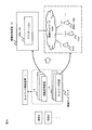
- FIG. 18 shows an outline of the sixth embodiment.
- the network control device 1 virtually constructs a network function provided by the wireless base station by using the network resource 13 and the information processing resource 14.
- the network control device 1 virtually constructs a wireless network including a BBU (Baseband Unit) 144, an RRH (Remote Radio Head) 133, and a control network 134.
- BBU Baseband Unit
- RRH Remote Radio Head
- control network 134 a control network 134.
- the BBU 144 and the RRH 133 are physically separated from each other.
- the network control device 1 constructs the RRH 133 and the control network 134 with the network resource 13 and constructs the BBU 144 with the information processing resource 14.
- the information processing resource control unit 12 of the network control apparatus 1 constructs the BBU 144 by placing an application having the function of the BBU 144 in the information processing resource 14.
- the radio base station has a function of performing digital baseband signal processing and a function of performing analog radio frequency (RF) signal processing.
- RF radio frequency
- the functions of this radio base station are separated into BBU 144 and RRH 133, respectively.
- the BBU 144 is connected to a higher-level network (eg, a core network of a telecommunications carrier), and executes control / monitoring of a radio base station and digital baseband signal processing.
- Digital baseband signal processing includes layer 2 signal processing and layer 1 (physical layer) signal processing.
- Layer 2 signal processing consists of (i) data compression / decompression, (ii) data encryption, (iii) layer 2 header addition / deletion, (iv) data segmentation / concatenation, and (v) data multiplexing. / At least one of generation / decomposition of transfer format by separation.
- the layer 2 signal processing includes processing of Radio Link Control (RLC) and Media Access Control (MAC).
- RLC Radio Link Control
- MAC Media Access Control
- Physical layer signal processing includes channel coding / decoding (Channel Coding / Decoding), modulation / demodulation (Spreading / De-spreading), resource mapping, and Inverse Fast Fourier Transform ( This includes generation of OFDM symbol data (baseband OFDM signal) by IFFT).
- RRH 133 is responsible for analog RF signal processing and provides an air interface to the mobile station.
- Analog RF signal processing includes D / A conversion, A / D conversion, frequency up-conversion, frequency down-conversion, amplification, and the like.
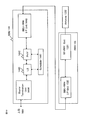
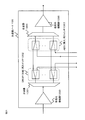
- FIG. 19 shows a configuration example of the BBU 144 and the RRH 133.
- FIG. 19 is an example, and the configurations of the BBU 144 and the RRH 133 are not limited to the example of FIG.
- Bearer Termination Unit 1444 terminates a bearer set up with a higher-level network (eg, GNTS RNC, E-UTRA EPC (Evolved Packet Core)) for transferring user data.
- the bearer for transferring user data (eg, S1 bearer of E-UTRA) is encrypted using, for example, a tunneling protocol (eg, IPsec).
- the bearer is set for each data flow (eg, E-UTRA Packet Data Network (PDN) connection) between the mobile station and the external network. Therefore, Bearer Termination Unit 1444 terminates at least one encrypted bearer, receives downlink user data related to multiple mobile stations from the higher level network, and receives uplink user data related to multiple mobile stations to the higher level network. Send to.
- PDN Packet Data Network
- Scheduler 1441 dynamically allocates each of a plurality of downlink and uplink radio resources to a mobile station connected to RRH 133 or user data thereof.
- Radio resources are distinguished by time, frequency, or spreading code, or a combination thereof.
- the radio resource is a resource block, and dynamic scheduling is performed using two resource blocks in one subframe (1 msec) as a minimum unit.
- One resource block has 12 subcarriers in the frequency domain and 7 OFDM symbols in the time domain.
- PHY1442 performs digital baseband signal processing related to the physical layer.
- Signal processing by PHY 1442 includes channel coding and modulation for transmitting downlink user data to the air interface. Further, the signal processing by PHY 1442 includes demodulation and channel decoding for recovering uplink user data from the received signal by the air interface.
- Channel encoding and decoding by PHY 1442 include, for example, block encoding or convolutional encoding, or a combination thereof. Transmission path encoding and decoding by PHY 1442 are performed using, for example, an encoding algorithm such as turbo code, Viterbi code, or Reed-Solomon code.
- the signal processing by the PHY 1442 may include spreading / de-spreading (Spreading / De-spreading), resource mapping, and OFDM signal generation with inverse fast Fourier transform (IFFT).
- IFFT inverse fast Fourier transform
- L2 1443 uses Bearer Termination Unit 1444 as an upper protocol layer and PHY 1442 as a lower protocol layer, and performs layer 2 signal processing excluding dynamic scheduling.
- Layer 2 signal processing includes (i) data compression / decompression, (ii) data encryption, (iii) layer 2 header addition / deletion, and data segmentation / concatenation, (v) data multiplexing / demultiplexing. At least one of the generation / decomposition of the transfer format according to.
- BBU-RRH I / F Units 1440 and 1330 are interfaces between the BBU 144 and the RRH 133.
- RF-PHY 1331 is connected to Antenna 1332 and performs analog RF signal processing related to the physical layer.
- the signal processing performed by the RF-PHY 1331 includes D / A conversion, A / D conversion, frequency up conversion, frequency down conversion, amplification, and the like.
- the network resource control unit 11 of the network control device 1 controls the network resource 13 so as to provide a function corresponding to the wireless network.
- the network resource control unit 11 controls the network resource 13 by, for example, the open flow technique illustrated in FIGS.
- the network resource control unit 11 selects the NW control module 151 for the wireless network from the SW repository 15, and controls the network resource 13 so as to perform an operation corresponding to the wireless network.
- FIG. 20 shows an operation example in which the network resource control unit 11 controls the network resource 13.
- the network resource 13 includes, for example, an RRH 133 and an optical communication node 135 for constructing the control network 134.
- the control network 134 is, for example, a ring network in which a plurality of optical communication nodes 135 are connected to a ring topology with optical fibers or the like.
- the network resource control unit 11 controls the network resource 13 of the control network 134 in order to establish a connection between the RRH 133 and the BBU 144.
- the network resource control unit 11 controls the optical communication node 135 by using, for example, ROADM (Reconfigurable Optical add / drop multiplexer).
- ROADM Reconfigurable Optical add / drop multiplexer
- an optical path is established by branching / inserting an optical signal.
- An optical path means a path of an optical signal dedicated to one wavelength.
- the network resource control unit 11 and the RRH 133 (B) are configured to “insert / ADD” an optical signal having a specific wavelength (a wavelength corresponding to the optical path to be established, for example, the wavelength X) transmitted from the RRH 133 (B).
- An operation rule is set for the optical communication node 135 to be connected.
- the network resource control unit 11 does not insert or branch an optical signal with respect to the optical communication node 135 (in the example of FIG. 20, the optical communication node 135 connected to the RRH 133 (C)) on the optical path.
- the operation rule is set to “pass / THRU”.
- the network resource control unit 11 sets an operation rule to “branch / DROP” the optical signal of wavelength X to the optical communication node 135 to which the BBU 144 is connected.
- the network resource control unit 11 establishes an optical path from the RRH 133 (B) to the BBU 144.
- Other optical paths are established in the same procedure as in the above-described operation example.
- FIG. 21 shows a configuration example of the optical communication node 135.
- the reception optical amplifier 1350 amplifies the reception light, and the demultiplexer 1351 demultiplexes the amplified reception light according to the wavelength.
- the DROP (branch) switch 1352 switches between branching or passing the demultiplexed optical signals of each wavelength.
- the network resource control unit 11 switches the switch so that the optical signal is branched (DROP) for the switch 1352 corresponding to the wavelength to be branched, and sends the optical signal to the switch 1352 that does not branch the optical signal otherwise. It passes through an ADD (insertion) switch 1353.
- the ADD (insertion) switch 1353 is a switch for inserting an optical signal having a wavelength corresponding to each switch.
- the network resource control unit 11 switches the switch so that an optical signal is inserted (ADD) with respect to the switch 1353 corresponding to the wavelength to be inserted into the ring network.
- the switch 1353 that does not insert the optical signal transmits the optical signal received from the branching switch 1352 to the multiplexer 1354.
- the multiplexer 1354 combines the optical signals having the wavelengths transmitted from the respective switches 1353, and the combined optical signals are amplified by the transmission optical amplifier 1355.
- the network control device 1 executes assignment of network resources 13 for virtually constructing a wireless network.
- the network control device 1 can acquire information regarding the communication quality of the wireless network via the RRH 133 and the BBU 144, and can increase or decrease the RRH 133 and the BBU 144 based on the information.
- the network control apparatus 1 determines to newly start the RRH 133 arranged in the vicinity of the area. .
- the network resource control unit 11 determines an identification condition for identifying the optical path in order to cause the optical communication node 135 to establish an optical path having a wavelength corresponding to the RRH 133 to be activated.
- the network resource control unit 11 notifies the optical communication node 135 of the operation rule generated based on the identification condition. In the example of FIG. 20, RRH 133 (B) is newly activated.
- the network resource control unit 11 notifies the node 135 connected to the RRH 133 (B) of an operation rule for “adding / ADDing” an optical signal having an optical path wavelength between the RRH 133 (B) and the BBU 144. .
- the network resource control unit 11 may determine a selection condition for selecting the BBU 144 that establishes an optical path with the activated RRH 133 based on the load status of the plurality of BBUs 144.
- the network resource control unit 11 notifies the node 135 of the operation rule determined based on the selection condition.
- the network control device 1 may measure the wireless communication throughput in each RRH 133 based on the acquired information. For example, the network control device 1 specifies an RRH 133 whose throughput is equal to or less than a predetermined threshold, and determines to newly start the RRH 133 arranged in the vicinity of the RRH 133. The network control device 1 can improve throughput by offloading communication with the newly activated RRH 133.
- the network resource control unit 11 of the network control device 1 constructs the control network 134 with newly assigned resources (for example, RRH 133).
- the network resource control unit 11 establishes the control network 134 by setting an optical path by the method illustrated in FIG. 20, for example.
- Embodiment 7 of the present invention relates to the function of the core network of the mobile operator.
- Embodiment 7 shows an example of virtually constructing a network function provided by a gateway device of a core network.
- FIG. 22 shows a configuration of a communication network related to eUTRAN (evolved UTRAN) access defined by 3GPP.
- the communication network includes an EPS (Evolved Packet System) 1000 and an external network 2000.
- the EPS 1000 includes an eNB 101, a router 102, an SGW 103, an MME 107, a router 104, a PGW 105, and a PCRF (Policy and Charging Rules Function) 106.
- the external network 2000 includes a router 201 and a service server 202.
- the router 102 relays communication between the eNB 101 and the SGW 103.
- the router 104 relays communication between the SGW 103 and the PGW 105.
- the SGW 103 is a logical node that accommodates a so-called 3G system in 3GPP and U-Plane (user traffic) with the LTE system.
- the 3G system mainly uses W-CDMA technology as a radio system.
- the SGW 103 includes an SGW constructed by virtualizing the information processing resource 14 by the network control device 1.
- the SGW 103 transmits the user traffic transmitted from the wireless terminal (UE: User Equipment) to the PGW 105 via the router 104.
- the user traffic has one of the IP addresses of the plurality of PGWs 105 as a destination address.
- the router 104 transfers the user traffic transmitted from the SGW 103 to the PGW 105 using a routing table in which the destination address and the destination device are associated with each other.
- the PGW 105 is a logical node having an interface function between the EPS 1000 and External network 2000. That is, data transmission / reception between the communication device in the EPS 1000 and the communication device in the External network 2000 is performed via the PGW 105.
- the PGW 105 includes a PGW constructed by virtualizing the information processing resource 14 by the network control device 1.
- the MME 107 has path control in the router 102, that is, functions such as setting a communication path between the eNB 101 and the SGW 103, terminal mobility management, authentication (security control), and the like.
- the PCRF 106 is a policy control device that determines policy control such as QoS and charging control rules applied in the PGW 103 and SGW 105.
- the PGW 103 and the SGW 105 perform policy control and the like based on the notification information from the PCRF 106.
- the router 201 relays communication between the PGW 105 and the service server 202.
- the service server 202 receives data via the router 201 and provides a service.
- the communication system according to the seventh embodiment can virtually construct a gateway (SGW 103 or PGW 105) and routers 102, 104, and 201 using the network resource 13 and the information processing resource 14.
- SGW 103 or PGW 105 The communication system according to the seventh embodiment can virtually construct a gateway (SGW 103 or PGW 105) and routers 102, 104, and 201 using the network resource 13 and the information processing resource 14.
- FIG. 23 shows an example of constructing a PGW virtually.
- the information processing resource control unit 12 of the network control device 1 places an application having the function of the PGW 105 in the information processing resource 14.
- the application arranged in the information processing resource 14 operates as a virtual PGW 105 (PGW (C) indicated by a broken line in FIG. 23).
- the information processing resource control unit 12 constructs a new PGW 105 according to the load status or congestion status of the PGW 105, or constructs an alternative PGW 105 according to the occurrence of a failure in the PGW 105. be able to.
- the network resource control unit 11 of the network control device 1 controls the network resource 13 so as to provide a network function corresponding to the virtually constructed PGW 105.
- the network resource control unit 11 selects the PGW NW control module 151 from the SW repository 15 by controlling the network resource 13 using the open flow technique illustrated in FIGS.
- the network resource 13 can be controlled so as to perform an operation corresponding to the above.
- the network resource control unit 11 illustrates the operation rules of the routing table of the router 104 (router (C)), for example, as illustrated in FIGS. Update.
- FIG. 24 shows, as an example, how the routing table of the router (C) is updated when a failure occurs in the PGW (B).
- the IP address of the PGW 105 (PGW (A)) is “a”
- the IP address of the PGW 105 (PGW (B)) is “b”
- the traffic addressed to the PGW (B) is newly constructed. ) Is sent to.
- the network resource control unit 11 updates this operation rule as follows. That is, traffic with the destination “IP Address: a” is forwarded to the PGW (A) as before the update, while traffic with the destination “IP Address: b” is forwarded to the added PGW (C). The operation rule is changed.
- the network resource control unit 11 also changes the routing table of the router 201 (router (F)) as in the example of FIG. That is, the network resource control unit 11 changes the routing table of the router (F) so as to transfer traffic addressed to the PGW (B) to the newly constructed PGW (C).
- the network resource control unit 11 can determine the traffic identification condition based on the destination address of the traffic.
- the network resource control unit 11 can also determine the selection conditions for the PGW 105 that is a traffic transfer destination based on the operation status of the PGW 105 (for example, whether or not a failure has occurred). That is, the network resource control unit 11 can determine the contents of the routing table set in the router 104 based on the identification condition and / or the selection condition.
- the network resource control unit 11 notifies the PGW (C) of session information including bearer information, control signal information, and the like set in the PGW (B). By notifying the PGW (C) of bearer information, session information, etc., it becomes possible to continue communication in the PGW (C) even when the session is switched from the PGW (B) to the PGW (C). .
- FIG. 25 shows, as an example, how the routing table of the router (C) is updated when congestion occurs in the PGW (B).
- the IP address of the PGW (A) is “a”
- the IP address of the PGW (B) is “b”
- the IP address of the newly constructed PGW (C) is “c”
- the network resource control unit 11 determines that the traffic of “IP Address: b” corresponds to an additional condition (conditions X and Y in the example of FIG. 25). Thus, the update is performed so that it is distributed to PGW (B) and PGW (C).
- the network resource control unit 11 can determine the traffic identification condition based on the destination address of the traffic. In addition to the selection conditions described above, the network resource control unit 11 can also use additional conditions in order to select a PGW as a traffic destination.
- Additional conditions are, for example, the IP address of the user terminal that is the source of the traffic, QoS (Quality of Service) information associated with the bearer between the eNodeB and the PGW, and the bearer identifier between the eNodeB and the PGW.
- QoS Quality of Service
- the conditions are determined based on attribute information such as TEID (Tunnel Endpoint Identifier).
- Condition X The end of the source IP address (for example, the portion of “1” at the end in 192.168.3.1) is an even number
- Condition Y The end of the source IP address is an odd number
- Condition X TEID is even
- Condition Y TEID is odd
- Condition X QCI (QoS Class Identifier) corresponding to bearer is 1-4
- Condition Y QCI corresponding to bearer is 5-9
- the conditions X and Y are classification conditions for classifying the attribute information according to the content of the information.
- the present invention is not limited to this.
- the network resource control unit 11 uses the network resource 13 to generate the router 104 (router (C)) and the router 201 (router (C)) in response to the newly launched PGW 105 (PGW (C)). F)) may be added to the communication network.
- the network resource control unit 11 assigns a new IP address (for example, “IP Address: c”) to the PGW (C).
- the network resource control unit 11 notifies the newly added router (C) and router (F) of a rule for forwarding the traffic whose destination is “IP Address: c” to the PGW (C).
- the network control device 1 virtually constructs a function related to the PGW.
- a function equivalent to the network control device 1 is added to the PCRF 106, and the PCRF 106 virtually constructs a function related to the PGW. Also good.
- the PCRF 106 may have the function of the network resource control unit 11 among the functions of the network control device 1.
- FIG. 27 shows an example in which the network control device 1 virtually constructs the functions of the SGW 103.
- the information processing resource control unit 12 of the network control device 1 places an application having the function of the SGW 103 in the information processing resource 14.
- the information processing resource control unit 12 constructs a new SGW 103 according to, for example, the load status or congestion status of the SGW 103. Further, the information processing resource control unit 12 may construct an alternative SGW 103 in response to the occurrence of a failure in the SGW 103.
- the network resource control unit 11 of the network control device 1 controls the network resource 13 so as to provide a function corresponding to the virtually constructed SGW 103.
- the network resource control unit 11 selects the SGW NW control module 151 from the SW repository 15, for example, by controlling the network resource 13 by the open flow technique illustrated in FIGS.
- the network resource 13 can be controlled to perform an operation corresponding to the SGW.
- the operation of the network resource system control unit 11 to control the network resource 13 is the same as the operation illustrated in FIGS.
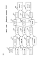
- FIGS. 28 and 29 are sequence diagrams illustrating an operation example of the seventh embodiment.
- FIG. 28 and FIG. 29 are examples, and the present invention is not limited to this operation example.
- FIG. 28 shows a bearer setting process sequence.
- the terminal 2 transmits an Establish bearer request to the PGW 105 in order to establish a path with the PGW 105 (operation S50).
- the PGW 105 transmits a PCC rule request to the PCRF 106 in order to obtain policy information and the like (operation S51).
- PCC is an abbreviation for Policy and Charging Control.
- the PCRF 106 transmits a PCC rule answer to the PGW 105 in order to set a PCC rule in the PGW 105 (operation S52).
- the PGW 105 transmits a PCC rule update to the PCRF 106 in order to notify the bearer information and control signal information corresponding to the PCC rule set in the PGW 105 (operation S53).
- the PCC rule defines policy information such as a bandwidth set for each bearer, charging information, and the like.
- the bearer information includes, for example, an IP address assigned to the terminal 2, a TEID, a QoS parameter, and the like.
- the control signal information includes, for example, an IP address assigned to the terminal 2, TEID-C, a restart counter of the own node, a restart counter of the corresponding node, and the like.
- the TEID is an identifier that identifies a tunnel for user data transmission set between the UE and the PGW 23.
- TEID-C is a tunnel identifier used on C-Plane.
- the PCRF 106 records bearer information, control signal information, and the like set in the PCC rule update.
- the PCRF 106 transmits a PCC rule answer to the PGW 105 as a response signal to the PCC rule update (operation S54). As a result of this operation, a bearer is established between the terminal 2 and the PGW 105 (operation S55).
- FIG. 29 shows an operation example when a new PGW 105 is constructed.
- the PCRF 106 has the function of the network control device 1.
- the network control apparatus 1 may execute the processing of the PCRF 106 in FIG. In this case, for example, the network control device 1 has the function of the PCRF 106.
- the PCRF 106 places an application having the function of the PGW 105 in the information processing resource 14 and activates a new PGW 105 (PGW (B)) (operation S60).
- PGW (B) is activated, and at least a part of the session established in PGW (A) is transferred to PGW (B).
- the PCRF 106 notifies the PGW (B) of the Install all policies rules for the affected session in order to notify the PGW (B) of the policy information of the session to be transferred to the PGW (B) (Operation S61).
- the policy information includes session information.
- the session information includes PCC rules, bearer information, control signal information, and the like.
- the PGW (B) notifies the PCRF 106 of the Install policy rule ack as a response signal to the Install all policy rules for the affected session (Operation S62).
- Operations S61 and S62 may be executed for each terminal 2 that has established a bearer with the PGW 105, and are executed in a batch using a bulk message to collectively transmit policy information of a plurality of terminals 2. May be.
- a bulk message to collectively transmit policy information of a plurality of terminals 2. May be.
- the PCRF 106 transmits a routing policy update to each router in order to update the routing tables of the routers 102 and 201 (operations S63 and S64).
- the PCRF 106 updates the routing table as in the examples of FIGS. 24 and 25, for example.
- the routers 102 and 201 transmit the routing policy update ack to the PCRF 106 (operations S65 and S66).
- the example of the seventh embodiment described above can also be applied to the construction of a GGSN (Gateway GPRS Support Node) or SGSN (Serving GPRS Support Node) of a communication system using UTRAN.
- GGSN Gateway GPRS Support Node
- SGSN Serving GPRS Support Node
- Embodiment 8 The network control device 1 according to the eighth embodiment of the present invention has a function of cooperating with a control device that controls various types of networks (for example, a wireless network, an access network, a core network, etc.).
- networks for example, a wireless network, an access network, a core network, etc.
- the network control device 1 can improve the operation efficiency of the operator by centrally managing various networks.
- the network control apparatus 1 in order to reduce the load increase of the network control apparatus 1 due to the concentration of the control processing of each network, the network control apparatus 1 according to the present embodiment is at least part of the function of virtually constructing the function of the dedicated appliance. Can be delegated to a control device arranged in each network. In this case, the operator constructs the function of the dedicated appliance via the network control device 1, but the actual processing is executed by the control device arranged in each network. With this configuration, it is possible to reduce the load on the network control device 1 while maintaining the operational efficiency of the operator.
- FIG. 30 shows an example of a system configuration according to the eighth embodiment of the present invention.
- Each network (for example, a wireless network, an access network, a core network, etc.) has a control device (for example, 1A, 1B, 1C in FIG. 30) that can virtually construct the function of a dedicated appliance in each network.
- each control device 1A-1C has the same functions as the network resource control unit 11 and the information processing resource control unit 12, respectively.
- the network resource control unit 11 and the information processing resource control unit 12 of each control device 1A-1C can operate based on an instruction from the network control device 1, respectively.
- the network control device 1 operates as a host control device of each control device 1A-1C.
- the network control device 1 that controls each control device 1A-1C has the same configuration as that of the other embodiments described above, for example. Further, the network control device 1 may have only a function of performing integrated control of the control devices 1A-1C.
- Each control device 1A-1C has, for example, a function of virtually constructing a dedicated appliance function related to a network managed by each control device 1A-1C.
- the network control device 1 instructs each control device 1A-1C to construct a function of the dedicated appliance.
- Each control device 1A-1C virtually constructs the function of the dedicated appliance in response to an instruction from the network control device 1.
- the network resource control unit 11 of each control device 1A-1C controls the operation of the network resource 13 in accordance with an instruction from the network control device 1.
- the network resource control unit 11 of each control device 1A-1C controls the network resource 13 using, for example, the network control module 151 corresponding to the function type of the dedicated appliance in the network of each control device 1A-1C.
- the management unit 10 of the network control device 1 has a function of integrally controlling the control devices 1A-1C. For example, the management unit 10 of the network control device 1 obtains information on the operation status of each network (for example, information processing resource 14 deployment status, network resource 13 topology information, etc.) via each of the control devices 1A-1C. collect.
- information on the operation status of each network for example, information processing resource 14 deployment status, network resource 13 topology information, etc.
- the control devices 1A-1C collect the network operation status (for example, the operation status of the network resource 13 and the information processing resource 14) managed by each control device, for example, by the technique described in the fourth embodiment.
- the management unit 10 of the control devices 1A-1C reports the collected information to the network control device 1.
- the network control device 1 acquires information collected by each control device 1A-1C, refers to the information, and instructs each control device 1A-1C to increase or reduce resources.
- Each control device 1A-1C executes enhancement or reduction of at least one of the network resource 13 and the information processing resource 14 in response to an instruction from the network control device 1.
- FIG. 31 shows another configuration example according to the eighth embodiment. In this embodiment, a part of the configuration of the third embodiment described above is applied to the eighth embodiment.
- Each control device 1A-1C has a SW repository (15A-15C).
- the network control device 1 stores the network function module 150 and the NW control module 151 for each SW repository (15A-15C).
- the network control device 1 stores modules that may be used in each network in each SW repository (15A-15C).
- the network control device 1 stores a module (for example, a module for virtualizing PGW, SGW, etc.) that may be used for virtualization of the core network in the SW repository 15C of the control device 1C.
- Each of the control devices 1A-1C virtually constructs the functions of the dedicated appliance using modules stored in the SW repository.
- Network Controller 1A Wireless Network Controller 1B Access Network Controller 1C Core Network Controller 10 Management Unit 100 OSS / BSS 11 Network Resource Control Unit 12 Information Processing Resource Control Unit 13 Network Resource 130 Rule Database 131 Communication Processing Unit 132 Switch 133 RRH 1330 BBU-RRH I / F Unit 1331 RF-PHY Unit 1332 Antenna 134 Control network 135 Optical communication node 1350 Reception optical amplifier 1351 Demultiplexer 1352 DROP switch 1353 Add switch 1354 Multiplexer 1355 Transmit optical amplifier 14 Information processing resource 140 BRAS 141 Access control unit 142 Session control unit 143 Authentication device 144 BBU 1440 BBU-RRH I / F Unit 1441 Scheduler 1442 PHY 1443 L2 1444 Bearer Termination Unit 15 SW Repository 150 Network Function Module 151 NW Control Module 101 eNB 102 router 103 SGW 104 router 105 PGW 106 PCRF 107 MME 201 Router 202 Service Server 2 Terminal 3 Service provider
Landscapes
- Engineering & Computer Science (AREA)
- Computer Networks & Wireless Communication (AREA)
- Signal Processing (AREA)
- Data Exchanges In Wide-Area Networks (AREA)
- Mobile Radio Communication Systems (AREA)
Abstract
Priority Applications (3)
| Application Number | Priority Date | Filing Date | Title |
|---|---|---|---|
| EP14804374.8A EP3007391B1 (fr) | 2013-05-27 | 2014-05-22 | Dispositif de commande de réseau, procédé de commande de réseau, programme associé et système de communication |
| US14/894,434 US20160127506A1 (en) | 2013-05-27 | 2014-05-22 | Network control apparatus, network control method, program, and communication system |
| JP2015519633A JPWO2014192259A1 (ja) | 2013-05-27 | 2014-05-22 | ネットワーク制御装置、ネットワーク制御方法、プログラムおよび通信システム |
Applications Claiming Priority (2)
| Application Number | Priority Date | Filing Date | Title |
|---|---|---|---|
| JP2013110934 | 2013-05-27 | ||
| JP2013-110934 | 2013-05-27 |
Publications (1)
| Publication Number | Publication Date |
|---|---|
| WO2014192259A1 true WO2014192259A1 (fr) | 2014-12-04 |
Family
ID=51988311
Family Applications (1)
| Application Number | Title | Priority Date | Filing Date |
|---|---|---|---|
| PCT/JP2014/002685 Ceased WO2014192259A1 (fr) | 2013-05-27 | 2014-05-22 | Dispositif de commande de réseau, procédé de commande de réseau, programme associé et système de communication |
Country Status (4)
| Country | Link |
|---|---|
| US (1) | US20160127506A1 (fr) |
| EP (1) | EP3007391B1 (fr) |
| JP (1) | JPWO2014192259A1 (fr) |
| WO (1) | WO2014192259A1 (fr) |
Cited By (5)
| Publication number | Priority date | Publication date | Assignee | Title |
|---|---|---|---|---|
| JP2016149719A (ja) * | 2015-02-13 | 2016-08-18 | 日本電信電話株式会社 | トラヒック振り分けシステム、トラヒック振り分け方法及びトラヒック振り分けプログラム |
| WO2017054841A1 (fr) * | 2015-09-28 | 2017-04-06 | Telefonaktiebolaget Lm Ericsson (Publ) | Fourniture de services à un équipement d'utilisateur itinérant |
| JPWO2017056201A1 (ja) * | 2015-09-29 | 2018-08-30 | 株式会社ソラコム | 移動体通信システムのゲートウェイの制御装置 |
| US10904802B2 (en) | 2016-03-29 | 2021-01-26 | Telefonaktiebolaget Lm Ericsson (Publ) | Service delivery to handed over user equipment (UE) using a software-defined networking (SDN) controller |
| JP2021525042A (ja) * | 2018-07-24 | 2021-09-16 | 中興通訊股▲ふん▼有限公司Zte Corporation | ベースバンド処理分離アーキテクチャにおける情報処理方法、装置及び記憶媒体 |
Families Citing this family (7)
| Publication number | Priority date | Publication date | Assignee | Title |
|---|---|---|---|---|
| TWI586124B (zh) * | 2013-04-26 | 2017-06-01 | Nec Corp | Communication node, communication system, packet processing method and program |
| AU2014399458B2 (en) * | 2014-06-30 | 2018-01-18 | Huawei Technologies Co., Ltd. | Flow Entry Configuration Method, Apparatus, and System |
| WO2016145629A1 (fr) * | 2015-03-18 | 2016-09-22 | 华为技术有限公司 | Procédé et appareil pour établir une communication dans un réseau social défini par logiciel et système de communication |
| US10332302B2 (en) | 2017-04-17 | 2019-06-25 | Intel Corporation | Scatter gather engine |
| US10560331B2 (en) | 2018-02-07 | 2020-02-11 | Juniper Networks, Inc. | Self-driven and adaptable multi-vBNG management orchestration |
| JP2020191497A (ja) * | 2019-05-20 | 2020-11-26 | トヨタ自動車株式会社 | 情報処理方法 |
| CN116094860A (zh) * | 2021-11-08 | 2023-05-09 | 美的集团股份有限公司 | 家电设备的配网方法及系统、电子设备及计算机存储介质 |
Citations (8)
| Publication number | Priority date | Publication date | Assignee | Title |
|---|---|---|---|---|
| WO2009098909A1 (fr) | 2008-02-04 | 2009-08-13 | Nec Corporation | Système d'attribution d'appareil virtuel |
| JP2011034403A (ja) | 2009-08-03 | 2011-02-17 | Ntt Data Corp | サービス実行装置、サービス実行方法 |
| WO2011068091A1 (fr) * | 2009-12-04 | 2011-06-09 | 日本電気株式会社 | Serveur et programme de contrôle de flux |
| WO2012093472A1 (fr) * | 2011-01-05 | 2012-07-12 | 株式会社日立製作所 | Procédé de gestion de réservation de service, système de machine virtuelle et support de stockage |
| WO2012176278A1 (fr) * | 2011-06-21 | 2012-12-27 | 富士通株式会社 | Dispositif de traitement d'informations, procédé de commande de machines virtuels et programme |
| JP2013003816A (ja) * | 2011-06-16 | 2013-01-07 | Hitachi Ltd | 仮想化ホームゲ−トウェイシステム |
| JP2013507044A (ja) * | 2009-09-30 | 2013-02-28 | アルカテル−ルーセント | クラウドトポロジでのエンタープライズ拡張のためのスケーラブルなアーキテクチャ |
| JP2013046298A (ja) * | 2011-08-25 | 2013-03-04 | Fujitsu Ltd | 通信方法、通信装置、および、通信プログラム |
Family Cites Families (14)
| Publication number | Priority date | Publication date | Assignee | Title |
|---|---|---|---|---|
| US7779097B2 (en) * | 2000-09-07 | 2010-08-17 | Sonic Solutions | Methods and systems for use in network management of content |
| US7917624B2 (en) * | 2004-11-18 | 2011-03-29 | Sanjay M. Gidwani | Wireless network having control plane segregation |
| DE102005027084A1 (de) * | 2005-06-11 | 2006-12-14 | Deutsche Thomson-Brandt Gmbh | Verfahren zum dynamischen Betrieb eines Software-Stapels sowie Vorrichtung zur Durchführung des Verfahrens |
| KR100718271B1 (ko) * | 2005-12-02 | 2007-05-15 | (재)대구경북과학기술연구원 | 하드웨어 디바이스 및 콘텐츠 자원공유를 위한 소프트웨어플랫폼이 장착된 임베디드 전자장치 |
| US7693044B2 (en) * | 2005-12-15 | 2010-04-06 | Nvidia Corporation | Single logical network interface for advanced load balancing and fail-over functionality |
| US8042122B2 (en) * | 2007-06-27 | 2011-10-18 | Microsoft Corporation | Hybrid resource manager |
| US8418168B2 (en) * | 2008-05-29 | 2013-04-09 | Research In Motion Limited | Method and system for performing a software upgrade on an electronic device connected to a computer |
| US9009329B2 (en) * | 2008-11-25 | 2015-04-14 | Microsoft Technology Licensing, Llc | Platform for enabling terminal services virtualization |
| JP5360199B2 (ja) * | 2009-03-31 | 2013-12-04 | 富士通株式会社 | 仮想計算機システム、情報処理装置、コンピュータプログラム及び接続制御方法 |
| AU2010242812A1 (en) * | 2009-05-01 | 2011-11-24 | Citrix Systems, Inc. | Systems and methods for providing a virtual appliance in an application delivery fabric |
| JP5444995B2 (ja) * | 2009-09-25 | 2014-03-19 | 沖電気工業株式会社 | セッション共有システム、方法及びプログラム、並びに、ユーザ端末 |
| US20130067093A1 (en) * | 2010-03-16 | 2013-03-14 | Optimi Corporation | Determining Essential Resources in a Wireless Network |
| EP3407547B1 (fr) * | 2011-08-17 | 2020-01-22 | Nicira, Inc. | Grappes de commande hiérarchique pour interconnecter différents domaines logiques |
| US8744439B2 (en) * | 2011-10-07 | 2014-06-03 | Apple Inc. | Methods and apparatus for intelligent initiation of connections within a network |
-
2014
- 2014-05-22 WO PCT/JP2014/002685 patent/WO2014192259A1/fr not_active Ceased
- 2014-05-22 EP EP14804374.8A patent/EP3007391B1/fr active Active
- 2014-05-22 US US14/894,434 patent/US20160127506A1/en not_active Abandoned
- 2014-05-22 JP JP2015519633A patent/JPWO2014192259A1/ja active Pending
Patent Citations (8)
| Publication number | Priority date | Publication date | Assignee | Title |
|---|---|---|---|---|
| WO2009098909A1 (fr) | 2008-02-04 | 2009-08-13 | Nec Corporation | Système d'attribution d'appareil virtuel |
| JP2011034403A (ja) | 2009-08-03 | 2011-02-17 | Ntt Data Corp | サービス実行装置、サービス実行方法 |
| JP2013507044A (ja) * | 2009-09-30 | 2013-02-28 | アルカテル−ルーセント | クラウドトポロジでのエンタープライズ拡張のためのスケーラブルなアーキテクチャ |
| WO2011068091A1 (fr) * | 2009-12-04 | 2011-06-09 | 日本電気株式会社 | Serveur et programme de contrôle de flux |
| WO2012093472A1 (fr) * | 2011-01-05 | 2012-07-12 | 株式会社日立製作所 | Procédé de gestion de réservation de service, système de machine virtuelle et support de stockage |
| JP2013003816A (ja) * | 2011-06-16 | 2013-01-07 | Hitachi Ltd | 仮想化ホームゲ−トウェイシステム |
| WO2012176278A1 (fr) * | 2011-06-21 | 2012-12-27 | 富士通株式会社 | Dispositif de traitement d'informations, procédé de commande de machines virtuels et programme |
| JP2013046298A (ja) * | 2011-08-25 | 2013-03-04 | Fujitsu Ltd | 通信方法、通信装置、および、通信プログラム |
Cited By (8)
| Publication number | Priority date | Publication date | Assignee | Title |
|---|---|---|---|---|
| JP2016149719A (ja) * | 2015-02-13 | 2016-08-18 | 日本電信電話株式会社 | トラヒック振り分けシステム、トラヒック振り分け方法及びトラヒック振り分けプログラム |
| WO2017054841A1 (fr) * | 2015-09-28 | 2017-04-06 | Telefonaktiebolaget Lm Ericsson (Publ) | Fourniture de services à un équipement d'utilisateur itinérant |
| US10595247B2 (en) | 2015-09-28 | 2020-03-17 | Telefonaktiebolaget Lm Ericsson (Publ) | Providing services to a roaming user equipment |
| JPWO2017056201A1 (ja) * | 2015-09-29 | 2018-08-30 | 株式会社ソラコム | 移動体通信システムのゲートウェイの制御装置 |
| US10904802B2 (en) | 2016-03-29 | 2021-01-26 | Telefonaktiebolaget Lm Ericsson (Publ) | Service delivery to handed over user equipment (UE) using a software-defined networking (SDN) controller |
| US12120557B2 (en) | 2016-03-29 | 2024-10-15 | Telefonaktiebolaget Lm Ericsson (Publ) | Service delivery to a roaming user equipment using a software-defined networking (SDN) controller |
| JP2021525042A (ja) * | 2018-07-24 | 2021-09-16 | 中興通訊股▲ふん▼有限公司Zte Corporation | ベースバンド処理分離アーキテクチャにおける情報処理方法、装置及び記憶媒体 |
| JP7031018B2 (ja) | 2018-07-24 | 2022-03-07 | 中興通訊股▲ふん▼有限公司 | ベースバンド処理分離アーキテクチャにおける情報処理方法、装置及び記憶媒体 |
Also Published As
| Publication number | Publication date |
|---|---|
| EP3007391A1 (fr) | 2016-04-13 |
| EP3007391A4 (fr) | 2017-01-25 |
| EP3007391B1 (fr) | 2019-06-26 |
| JPWO2014192259A1 (ja) | 2017-02-23 |
| US20160127506A1 (en) | 2016-05-05 |
Similar Documents
| Publication | Publication Date | Title |
|---|---|---|
| EP3007391B1 (fr) | Dispositif de commande de réseau, procédé de commande de réseau, programme associé et système de communication | |
| CN105993188B (zh) | 网络控制设备、通信设备、网络控制方法、通信方法、通信系统和程序 | |
| US12407754B2 (en) | Control apparatus for gateway in mobile communication system | |
| KR102087226B1 (ko) | 다수의 사업자 지원을 위한 sdn 기반의 네트워크 공유 방법 | |
| WO2014199646A1 (fr) | Procédé et dispositif de régulation de la qualité de service dans un système de communication, et dispositif de communication | |
| CN114128228A (zh) | 通过SRv6头传输MTNC-ID以实现5G传输 | |
| CN114710975A (zh) | 多域间传输多传输网络上下文标识 | |
| CN114128227A (zh) | 在支持SRv6的数据面上传输MTNC-ID以实现5G传输 | |
| WO2015113285A1 (fr) | Procédé de contrôle et contrôleur centralisé dans un réseau de communication et un système de réseau de communication sans fil | |
| EP3107325B1 (fr) | Dispositif de commande de réseau, procédé de commande de réseau, système de communication et programme | |
| JP6515920B2 (ja) | 通信装置、通信方法、通信システムおよびプログラム | |
| US9413647B2 (en) | Multi-protocol label switching (MPLS) functionality in a communications network between a first node and a second node via a wireless connection | |
| JP6485362B2 (ja) | ネットワーク制御装置、通信装置、制御方法、通信方法およびプログラム | |
| Cui et al. | Policy-based flow control for multi-homed mobile terminals with IEEE 802.11 u standard | |
| WO2015045575A1 (fr) | Système de réseau, procédé de gestion et gestionnaire de réseau |
Legal Events
| Date | Code | Title | Description |
|---|---|---|---|
| 121 | Ep: the epo has been informed by wipo that ep was designated in this application |
Ref document number: 14804374 Country of ref document: EP Kind code of ref document: A1 |
|
| ENP | Entry into the national phase |
Ref document number: 2015519633 Country of ref document: JP Kind code of ref document: A |
|
| NENP | Non-entry into the national phase |
Ref country code: DE |
|
| WWE | Wipo information: entry into national phase |
Ref document number: 14894434 Country of ref document: US |
|
| WWE | Wipo information: entry into national phase |
Ref document number: 2014804374 Country of ref document: EP |