WO2014192305A1 - Système de communication, stations de base, et procédé de contrôle de communications - Google Patents
Système de communication, stations de base, et procédé de contrôle de communications Download PDFInfo
- Publication number
- WO2014192305A1 WO2014192305A1 PCT/JP2014/002857 JP2014002857W WO2014192305A1 WO 2014192305 A1 WO2014192305 A1 WO 2014192305A1 JP 2014002857 W JP2014002857 W JP 2014002857W WO 2014192305 A1 WO2014192305 A1 WO 2014192305A1
- Authority
- WO
- WIPO (PCT)
- Prior art keywords
- base station
- station
- communication system
- communication
- carrier
- Prior art date
- Legal status (The legal status is an assumption and is not a legal conclusion. Google has not performed a legal analysis and makes no representation as to the accuracy of the status listed.)
- Ceased
Links
Images




Classifications
-
- H—ELECTRICITY
- H04—ELECTRIC COMMUNICATION TECHNIQUE
- H04W—WIRELESS COMMUNICATION NETWORKS
- H04W72/00—Local resource management
- H04W72/04—Wireless resource allocation
- H04W72/044—Wireless resource allocation based on the type of the allocated resource
- H04W72/0453—Resources in frequency domain, e.g. a carrier in FDMA
-
- H—ELECTRICITY
- H04—ELECTRIC COMMUNICATION TECHNIQUE
- H04J—MULTIPLEX COMMUNICATION
- H04J11/00—Orthogonal multiplex systems, e.g. using WALSH codes
-
- H—ELECTRICITY
- H04—ELECTRIC COMMUNICATION TECHNIQUE
- H04L—TRANSMISSION OF DIGITAL INFORMATION, e.g. TELEGRAPHIC COMMUNICATION
- H04L1/00—Arrangements for detecting or preventing errors in the information received
-
- H—ELECTRICITY
- H04—ELECTRIC COMMUNICATION TECHNIQUE
- H04L—TRANSMISSION OF DIGITAL INFORMATION, e.g. TELEGRAPHIC COMMUNICATION
- H04L1/00—Arrangements for detecting or preventing errors in the information received
- H04L1/0001—Systems modifying transmission characteristics according to link quality, e.g. power backoff
- H04L1/0002—Systems modifying transmission characteristics according to link quality, e.g. power backoff by adapting the transmission rate
- H04L1/0003—Systems modifying transmission characteristics according to link quality, e.g. power backoff by adapting the transmission rate by switching between different modulation schemes
-
- H—ELECTRICITY
- H04—ELECTRIC COMMUNICATION TECHNIQUE
- H04L—TRANSMISSION OF DIGITAL INFORMATION, e.g. TELEGRAPHIC COMMUNICATION
- H04L1/00—Arrangements for detecting or preventing errors in the information received
- H04L1/0001—Systems modifying transmission characteristics according to link quality, e.g. power backoff
- H04L1/0009—Systems modifying transmission characteristics according to link quality, e.g. power backoff by adapting the channel coding
-
- H—ELECTRICITY
- H04—ELECTRIC COMMUNICATION TECHNIQUE
- H04L—TRANSMISSION OF DIGITAL INFORMATION, e.g. TELEGRAPHIC COMMUNICATION
- H04L1/00—Arrangements for detecting or preventing errors in the information received
- H04L1/0001—Systems modifying transmission characteristics according to link quality, e.g. power backoff
- H04L1/0015—Systems modifying transmission characteristics according to link quality, e.g. power backoff characterised by the adaptation strategy
-
- H—ELECTRICITY
- H04—ELECTRIC COMMUNICATION TECHNIQUE
- H04L—TRANSMISSION OF DIGITAL INFORMATION, e.g. TELEGRAPHIC COMMUNICATION
- H04L5/00—Arrangements affording multiple use of the transmission path
- H04L5/003—Arrangements for allocating sub-channels of the transmission path
- H04L5/0032—Distributed allocation, i.e. involving a plurality of allocating devices, each making partial allocation
- H04L5/0035—Resource allocation in a cooperative multipoint environment
-
- H—ELECTRICITY
- H04—ELECTRIC COMMUNICATION TECHNIQUE
- H04L—TRANSMISSION OF DIGITAL INFORMATION, e.g. TELEGRAPHIC COMMUNICATION
- H04L5/00—Arrangements affording multiple use of the transmission path
- H04L5/003—Arrangements for allocating sub-channels of the transmission path
- H04L5/0048—Allocation of pilot signals, i.e. of signals known to the receiver
-
- H—ELECTRICITY
- H04—ELECTRIC COMMUNICATION TECHNIQUE
- H04L—TRANSMISSION OF DIGITAL INFORMATION, e.g. TELEGRAPHIC COMMUNICATION
- H04L5/00—Arrangements affording multiple use of the transmission path
- H04L5/003—Arrangements for allocating sub-channels of the transmission path
- H04L5/0058—Allocation criteria
- H04L5/0073—Allocation arrangements that take into account other cell interferences
-
- H—ELECTRICITY
- H04—ELECTRIC COMMUNICATION TECHNIQUE
- H04W—WIRELESS COMMUNICATION NETWORKS
- H04W72/00—Local resource management
Definitions
- the present invention relates to a communication system, a base station, and a communication control method.
- a carrier wave used for transmission can have a frequency bandwidth (hereinafter referred to as a bandwidth) of 1.4 MHz, 3 MHz, 5 MHz, 10 MHz, and 20 MHz (non-bandwidth).
- a bandwidth 1.4 MHz, 3 MHz, 5 MHz, 10 MHz, and 20 MHz (non-bandwidth).
- the number of resource blocks (RB) included in each bandwidth is 6 RB, 15 RB, 25 RB, 50 RB, and 100 RB, respectively.
- the bandwidth increases, the communication speed increases.
- An area having a bandwidth of 9 MHz (hereinafter referred to as 9 MHz band or second frequency band) is allocated as a frequency band of public PHS from 1884.5 MHz to 1893.5 MHz.
- the carrier bandwidth is set to 5 MHz (hereinafter also referred to as a first frequency bandwidth) so as to be within the bandwidth of 9 MHz, and one carrier is arranged. Conceivable.
- the bandwidth is 5 MHz, the communication speed will be lower than when the bandwidth is 10 MHz.
- the bandwidth of 9 MHz which is the bandwidth, is used for communication, the use efficiency of communication resources is deteriorated.
- an object of the present invention made in view of the above problems is to allocate a carrier speed in a communication system such as TD-LTE to ensure a carrier bandwidth and increase the communication speed.
- Another object of the present invention is to provide a communication system, a base station, and a communication control method that can prevent a radio wave interference with other systems by placing a carrier in a frequency band (for example, 9 MHz band).
- a communication system provides: A plurality of bases that perform radio communication by arranging a plurality of the carriers in the second frequency band that exceeds the bandwidth of the second frequency band defined in advance when the carriers of the first frequency bandwidth are continuously arranged.
- a communication system comprising a station, The communication system is arranged by overlapping a part of each carrier in the second frequency band, The first base station that uses one of the carriers that is partially overlapped is preferentially assigned to one of the overlapping portions with respect to the allocation of user data over the second base station that uses the other carrier. It is characterized by using some radio resources.
- the communication system includes: The first base station and the second base station use radio resources having different arrangements in the overlapping portion with respect to reference signal allocation.
- the communication system according to the present invention includes: The second base station does not transmit the reference signal in the radio resource to which the first base station preferentially allocates user data.
- the communication system includes: The second base station uses a radio resource having a different arrangement from the control channel of the first base station for allocation of a predetermined control signal.
- the communication system includes: A plurality of bases that perform radio communication by arranging a plurality of the carriers in the second frequency band that exceeds the bandwidth of the second frequency band defined in advance when the carriers of the first frequency bandwidth are continuously arranged.
- a communication system comprising a station, The communication system is arranged by overlapping a part of each carrier in the second frequency band, The first base station that uses one of the carriers that is partially overlapped and the second base station that uses the other carrier are based on the MCS (Modulation and Coding Scheme) of the mobile station. It is characterized by controlling radio resource allocation in the overlapping part.
- MCS Modulation and Coding Scheme
- the communication system includes: When the MCS of the mobile station connected to the first base station and the second base station is equal to or greater than a predetermined first threshold, the first base station and the second base station allocate the overlapping portion of radio resources to the mobile station. It is characterized by lowering the priority.
- the communication system includes: Radio resource in which user data of the first base station collides with a reference signal of the second base station when the MCS of the mobile station connected to the first base station is less than a predetermined second threshold The first base station does not transmit user data, and the second base station transmits a reference signal.
- the communication system includes: Radio resource in which user data of the first base station collides with a reference signal of the second base station when the MCS of the mobile station connected to the first base station is equal to or greater than a predetermined second threshold
- the first base station transmits user data, and the second base station does not transmit a reference signal.
- the base station according to the present invention is: A plurality of bases that perform radio communication by arranging a plurality of the carriers in the second frequency band that exceeds the bandwidth of the second frequency band defined in advance when the carriers of the first frequency bandwidth are continuously arranged.
- a base station in a communication system comprising a station, In the second frequency band, a part of each carrier is arranged overlappingly, and one of the carriers arranged overlapping the part is used, With respect to user data allocation, a portion that is preferentially used by each base station among the wireless resources of the overlapping portion is distinguished.
- the base station according to the present invention is: Regarding the allocation of reference signals, the base stations use radio resources having different arrangements in the overlapping portion.
- the base station according to the present invention is: The reference signal is not transmitted in the portion that is preferentially used for the allocation of user data by another base station using the other carrier.
- the base station according to the present invention is: A radio resource having a different arrangement from the control channel of another base station that uses the other carrier is used for allocation of a predetermined control signal.
- the base station is: A plurality of bases that perform radio communication by arranging a plurality of the carriers in the second frequency band that exceeds the bandwidth of the second frequency band defined in advance when the carriers of the first frequency bandwidth are continuously arranged.
- a base station in a communication system comprising a station, In the second frequency band, a part of each carrier is arranged in an overlapping manner, and one carrier in which the part is arranged in an overlapping manner is used, The radio resource allocation in the overlapping part is controlled based on MCS (Modulation and Coding Scheme) of the mobile station.
- MCS Modulation and Coding Scheme
- the base station according to the present invention is: When the MCS of the mobile station connected to the local station is equal to or greater than a predetermined first threshold, the priority for allocating the overlapping radio resources to the mobile station is lowered.
- the base station according to the present invention is: In the radio resource in which the reference signal of the other base station using the other carrier and the user data of the own station collide, When the MCS of the mobile station connected to the local station is equal to or greater than a predetermined second threshold, user data is transmitted, When the MCS of the mobile station connected to the own station is less than a predetermined second threshold, user data is not transmitted.
- the base station according to the present invention is: In radio resources where user data of another base station using the other carrier collides with the reference signal of the own station, If the MCS of the mobile station connected to the other base station is equal to or greater than a predetermined second threshold, the reference signal is not transmitted, A reference signal is transmitted when the MCS of the mobile station connected to the other base station is less than a predetermined second threshold.
- the communication control method includes: A plurality of bases that perform radio communication by arranging a plurality of the carriers in the second frequency band that exceeds the bandwidth of the second frequency band defined in advance when the carriers of the first frequency bandwidth are continuously arranged.
- a communication control method of a communication system including a station The communication system is arranged by overlapping a part of each carrier in the second frequency band, A first base station that uses one of the carriers that is partially overlapped is preferentially assigned to one of the overlapping portions over a second base station that uses the other carrier in terms of user data allocation. It is characterized by using some radio resources.
- the communication control method according to the present invention includes: The first base station and the second base station use radio resources having different arrangements in the overlapping portion with respect to reference signal allocation.
- the communication control method includes: The second base station does not transmit the reference signal in the radio resource to which the first base station preferentially allocates user data.
- the communication control method includes: The second base station uses a radio resource having a different arrangement from the control channel of the first base station for allocation of a predetermined control signal.
- the communication control method includes: A plurality of bases that perform radio communication by arranging a plurality of the carriers in the second frequency band that exceeds the bandwidth of the second frequency band defined in advance when the carriers of the first frequency bandwidth are continuously arranged.
- MCS Modulation and Coding Scheme
- the communication control method includes: Radio resource in which user data of the first base station collides with a reference signal of the second base station when the MCS of the mobile station connected to the first base station is less than a predetermined second threshold The first base station does not transmit user data, and the second base station transmits a reference signal.
- the communication control method includes: Radio resource in which user data of the first base station collides with a reference signal of the second base station when the MCS of the mobile station connected to the first base station is equal to or greater than a predetermined second threshold
- the first base station transmits user data, and the second base station does not transmit a reference signal.
- the carrier bandwidth is secured to increase the communication speed, and the frequency allocated to the communication system It is possible to prevent radio wave interference with other systems by placing the carrier in the band (for example, 9 MHz band).
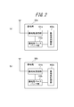
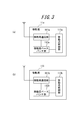
- FIG. 1 is a schematic diagram of a communication system according to Embodiment 1 of the present invention. It is a block diagram of the base station which concerns on Embodiment 1 of this invention.
- FIG. 2 is a block diagram of a mobile station according to Embodiment 1 of the present invention. It is an arrangement
- FIG. 6 is a diagram illustrating an example of radio resource allocation in the first ODFM symbol of FIG. 5. It is a flowchart which shows operation
- FIG. 1 is a schematic diagram of a communication system 1 according to Embodiment 1 of the present invention.
- the communication system 1 according to Embodiment 1 of the present invention includes a plurality of communication devices.
- the communication system 1 includes a communication device 10a (base station 10a) and a communication device 10b (base station 10b), each of which includes a communication device 11a (mobile station 11a) and a communication device 11b (mobile station 11b). ) Is connected.
- FIG. 1 shows an example in which two base stations and two mobile stations are provided, the present invention is not limited to this, and there may be two or more base stations and mobile stations.
- the base station 10a and the base station 10b are configured to be communicable.
- the communication system 1 is a system that employs a communication method such as TD-LTE or LTE.
- a communication method such as TD-LTE or LTE.
- the communication system 1 performs wireless communication by arranging two carriers having a bandwidth (first frequency bandwidth) of 5 MHz (effective bandwidth is 4.5 MHz) in the 9 MHz band (second frequency band).
- the two carriers arranged in the second frequency band are referred to as carrier A and carrier B.
- the base station 10a and the communication device 11a communicate using the carrier A
- the base station 10b and the communication device 11b communicate using the carrier B.
- the base station 10a includes a base station communication unit 101a, a base station baseband unit 102a, and a base station control unit 103a.
- the base station communication unit 101a and the base station baseband unit 102a are connected to the base station control unit 103a.
- the base station communication unit 101a transmits and receives radio signals (data) to and from the mobile station 11a via an antenna.
- the base station communication unit 101a performs amplification and down-conversion with low noise on the received radio signal (reception signal), and sends the processed signal to the base station baseband unit 102a. Further, the base station communication unit 101a performs up-conversion and amplification on the baseband signal received from the base station baseband unit 102a, and generates a radio signal (transmission signal). Then, the base station communication unit 101a transmits the radio signal to the mobile station 11a via the antenna.
- the base station baseband unit 102a demodulates the received signal by performing AD conversion, fast Fourier transform, and the like on the signal received from the base station communication unit 101a, and extracts the baseband signal. Then, the base station baseband unit 102a sends a baseband signal to the base station control unit 103a.
- the base station baseband unit 102a modulates the baseband signal by performing inverse fast Fourier transform, DA conversion, and the like on the baseband signal generated by the base station control unit 103a. Then, the modulated baseband signal is sent to the base station communication unit 101a.
- the base station baseband unit 102a extracts a CQI (Channel Quality Indicator) indicating channel quality from the radio signal (CQI report) received from the mobile station 11a. Then, the base station baseband unit 102a sends the extracted CQI to the base station control unit 103a.
- CQI Channel Quality Indicator
- the base station control unit 103a controls and manages the entire base station 10a including each functional block of the base station 10a.
- the base station control unit 103a is configured as software executed on any suitable processor such as a CPU (central processing unit), or by a dedicated processor (for example, DSP (digital signal processor)) specialized for each process. It can also be configured.
- the base station control unit 103a uses the carrier A having the first frequency bandwidth in order to realize wireless communication between the base station 10a and the mobile station 11a. Specifically, the base station control unit 103a allocates the used downlink radio resources and the used uplink radio resources that are part of the carrier A to the mobile station 11a (and other mobile stations connected to the base station 10a).
- the used downlink radio resource is a radio resource that the base station uses in downlink communication (downlink) with the mobile station.
- the used uplink radio resource is a radio resource used by the mobile station in uplink communication (uplink) with the base station.
- the base station control unit 103a communicates with the mobile station 11a using the allocated use downlink radio resource and use uplink radio resource.
- the base station control unit 103a transmits the information on the assigned downlink radio resources and uplink uplink radio resources to the mobile station 11a (and other mobile stations connected to the base station 10a) via the base station communication unit 101a. Send.
- PF Proportional Fair
- PF is a scheduling method for allocating the RB to a mobile station having a large instantaneous SINR with respect to an average SINR (Signal toInterference plus Noise power Ratio) for each RB.
- the base station control unit 103a determines the most efficient MCS (Modulation and Coding Scheme) that satisfies a predetermined BLER (Block Error and Rate) with the assigned radio resource.
- MCS Modulation and Coding Scheme
- MCS is a value from 0 to 28 indicating a combination of a data modulation scheme and a channel coding rate used for transmission of a radio signal. While the efficiency is higher as the MCS value is larger, the coding strength of the radio signal is lowered.
- the allocation of radio resources according to the type of radio signal transmitted by the base station 10a will be described later with reference to FIGS.
- the base station 10b has the same configuration as the base station 10a.
- the base station communication unit 101b and the base station baseband unit 102b perform the same operations as the base station communication unit 101a and the base station baseband unit 102a, respectively.
- the base station control unit 103b of the base station 10b uses the carrier B having the first frequency bandwidth in order to realize wireless communication between the base station 10b and the mobile station 11b. Specifically, the base station control unit 103b allocates the used downlink radio resources and the used uplink radio resources that are part of the carrier B to the mobile station 11b (and other mobile stations connected to the base station 10b). Then, the base station control unit 103b communicates with the mobile station 11b using the allocated use downlink radio resource and use uplink radio resource. In addition, the base station control unit 103b sends the information on the assigned downlink radio resources and uplink uplink radio resources to the mobile station 11b (and other mobile stations connected to the base station 10b) via the base station communication unit 101b. Send.
- Allocation of radio resources performed for each mobile station connected to the base station 10b is performed based on a scheduling algorithm such as PF using the CQI extracted by the base station baseband unit 102b. Further, the base station control unit 103b determines the most efficient MCS that satisfies a predetermined BLER with the assigned radio resource. The allocation of radio resources according to the type of radio signal transmitted by the base station 10b will be described later with reference to FIGS.
- the mobile station 11a includes a mobile station communication unit 111a, a mobile station baseband unit 112a, and a mobile station control unit 113a.
- the mobile station communication unit 111a and the mobile station baseband unit 112a are connected to the mobile station control unit 113a.
- the mobile station communication unit 111a transmits and receives radio signals (data) to and from the base station 10a via an antenna.
- the mobile station communication unit 111a performs amplification and down-conversion with low noise on the received radio signal (reception signal), and sends the processed signal to the mobile station baseband unit 112a.
- the mobile station communication unit 111a performs up-conversion and amplification on the baseband signal received from the mobile station baseband unit 112a to generate a radio signal (transmission signal). Then, the mobile station communication unit 111a transmits the radio signal to the base station 10a via the antenna.
- the mobile station baseband unit 112a demodulates the received signal by performing AD conversion, fast Fourier transform, and the like on the signal received from the mobile station communication unit 111a, and extracts the baseband signal. Then, the mobile station baseband unit 112a sends a baseband signal to the mobile station control unit 113a.
- the mobile station baseband unit 112a modulates the baseband signal by performing inverse fast Fourier transform, DA conversion, and the like on the baseband signal generated by the mobile station control unit 113a.
- the modulated baseband signal is sent to the mobile station communication unit 111a.
- the mobile station control unit 113a controls and manages the entire mobile station 11a including each functional block of the mobile station 11a.
- the mobile station control unit 113a is configured as software executed on an arbitrary suitable processor such as a CPU (Central Processing Unit), or by a dedicated processor (for example, DSP (Digital Signal Processor)) specialized for each process. It can also be configured.
- a CPU Central Processing Unit
- DSP Digital Signal Processor
- the mobile station control unit 113a determines the radio resource to be used, the modulation scheme, and the coding rate based on the allocation information of the used downlink radio resource and the used uplink radio resource in the carrier A received from the base station 10a. . Then, the mobile station control unit 113a performs radio communication with the base station 10a through the mobile station communication unit 111a and the mobile station baseband unit 112a using the determined radio resource, modulation scheme, and coding rate. Further, the mobile station control unit 113a generates a CQI report as information related to channel quality at a predetermined cycle. Preferably, when generating the CQI report, the mobile station control unit 113a uses a higher layer-configured subband feedback (Mode 3-0, Mode 3-1) or UE- Use selected subband feedback (Mode 2-0, Mode 2-2).
- the mobile station 11b has the same configuration as the mobile station 11a.
- the mobile station communication unit 111b and the mobile station baseband unit 112b perform the same operations as the mobile station communication unit 111a and the mobile station baseband unit 112a, respectively.
- the mobile station control unit 113b of the mobile station 11b uses the radio resources to be used, the modulation scheme, and the encoding based on the allocation information of the used downlink radio resources and the used uplink radio resources in the carrier B received from the base station 10b. Determine the rate. Then, the mobile station control unit 113b performs radio communication with the base station 10b by the mobile station communication unit 111b and the mobile station baseband unit 112b using the determined radio resource, modulation scheme, and coding rate. Further, the mobile station control unit 113b generates a CQI report as information related to channel quality at a predetermined cycle.
- the mobile station control unit 113b when generating the CQI report, in order to eliminate the influence of the channel quality of the overlapping portion, Higher Layer-configured subband feedback (Mode 3-0, Mode 3-1) or UE- Use selected subband feedback (Mode 2-0, Mode 2-2).
- Mode 3-0 Higher Layer-configured subband feedback
- Mode 2-2 UE- Use selected subband feedback
- FIG. 4 shows a schematic diagram in which a part of the carrier A and the carrier B are overlapped. As shown in FIG.
- a peripheral band of the 9 MHz band a 1.7G mobile phone band, a guard band band, a public PHS band (9 MHz band), a digital cordless telephone band, a public PHS band, a guard band band, and a 2G mobile phone Bandwidth is less than 1879.9 MHz, 1879.9 MHz to 1884.5 MHz, 1884.5 MHz to 1893.5 MHz, 1893.5 MHz to 1906.1 MHz, 1906.1 to 1915.7 MHz, 1915.7 MHz to 1920 MHz, 1920 MHz or more Assigned. As shown in FIG. 4, in the communication system 1, the carrier A and the carrier B are partially overlapped and arranged in the 9 MHz band.
- the center frequency of the carrier is assigned in units of 0.1 MHz based on the LTE standard (Non-Patent Document 1)
- most of the frequency band of carrier A is between 1884.5 MHz and 1889.5 MHz.
- most of the frequency band of carrier B is located between 1888.5 and 1893.5 MHz.
- the carrier A and the carrier B are overlapped in a 1 MHz portion between 1888.5 MHz and 1889.5 MHz, for example.
- the overlapping part is referred to as an overlapping part (or overlap band).
- FIG. 5 is a diagram showing an example of radio resource allocation in the downlink according to Embodiment 1 of the present invention.
- the base station 10a and the base station 10b perform radio communication by dividing radio resources preferentially used by each base station for transmission of radio signals in overlapping portions of carriers.
- FIG. 5A shows a state where carrier A and carrier B each having 25 RBs per slot are overlapped by 5 RBs to form a band having 45 RBs as a whole.
- one subframe consisting of two slots is shown in the time axis direction, and RB numbers from 0 to 44 are assigned as index numbers. Further, in FIG.
- a control information area to which a control channel such as PDCCH (PhysicalPhysDownlink Control Channel) is assigned is omitted, and a user data area to which a shared channel such as PDSCH (Physical Downlink Shared Channel) is assigned. Only shows.
- the PDCCH is a channel that transmits control information related to the connection between the base station and the mobile station.
- the PDSCH is a channel for transmitting user data related to downloading from the base station to the mobile station.
- the low frequency side is assumed to be carrier A and the high frequency side is assumed to be carrier B.
- PBCH Physical Broadcast Channel
- PSS Primary Synchronization Signal
- SSS Secondary chron Synchronization Signal
- the base station 10a performs scheduling by distributed RB allocation in order to reduce the influence of collision in overlapping portions.
- the base station 10a since the 24th RB does not perform frequency hopping, the base station 10a uses the 0th to 23rd RBs for PDSCH allocation, and does not use the 24th RB.
- the base station 10b performs scheduling based on local RB allocation using RBs 24 to 44 for PDSCH allocation.
- the base station 10a preferentially uses a part of the overlapping part, that is, the 20th to 23rd RBs, so that the PDSCH collides in the overlapping part. Can be prevented.
- FIG.5 (b) is a figure which shows the detail of 19th and 20th RB in Fig.5 (a).
- 1 RB has 12 subcarriers in the frequency axis direction, and has 1 slot consisting of 7 OFDM symbols in the time axis direction.
- the top three symbols are used as a control information area to which PDCCH and the like are allocated, and the remaining 11 symbols are used as a user data area to which PDSCH and the like are allocated.
- FIG. 5B shows an example of assignment of reference signals corresponding to the antenna port 0 and the antenna port 1 of the base station 10a and the base station 10b.
- a reference signal is assigned to two REs (Resource Element) with a predetermined arrangement per 6 subcarriers for each antenna port (Non-patent Document 2). Since the 19th RB is not an overlapping portion, reference signals respectively corresponding to the antenna port 0 and the antenna port 1 of the carrier A are allocated.
- the reference signal of the base station 10b is further allocated.
- the base station 10b transmits a reference signal using radio resources that do not collide with each other due to a different arrangement from the base station 10a.
- the base station 10a and the base station 10b transmit reference signals using different subcarriers in 1 RB by adjusting cell IDs between carriers. That is, the base station 10a and the base station 10b differ in the arrangement of reference signals to be transmitted in the overlapping portion.
- the cell ID is an identifier for identifying each of the base station 10a and the base station 10b, and can be appropriately changed by the base station control unit 103a and the base station control unit 103b. Then, the base station control unit 103a and the base station control unit 103b determine the initial offset of the reference signal based on the cell ID, that is, the allocation start position in the frequency axis direction.
- the base station 10a and the base station 10b can prevent the reference signals from colliding with each other in the overlapping portion by transmitting the reference signals using radio resources having different arrangements.
- the PDCCH is allocated in units of one REG (Resource Element Group) consisting of 4 REs in the head symbol of the subframe.
- REG Resource Element Group
- 1RB except for the RE to which the reference signal is allocated, there are a total of two REGs consisting of four subcarriers on the low frequency side (hereinafter referred to as the first half REG) and REG consisting of four subcarriers on the high frequency side (hereinafter referred to as the second half REG).
- REG is included.
- the PDCCH has four CCEs (Control Channels Element) using 9REG, and has 36 REGs in total.
- the base station 10 a allocates PCFICH (Physical Control Format Indicator Channel) and PHICH (Physical HARQ Indicator Channel) and avoids overlapping parts, and then PCFICH and PHICH are assigned. Interleave is performed on non-radio resources and PDCCHs are allocated in order from the low frequency side.
- PCFICH is a channel for transmitting information indicating the number of symbols used as a control signal area in a subframe.
- PHICH is a channel for transmitting delivery confirmation information of a radio signal transmitted by a mobile station. Based on the LTE standard, PCFICH has four REGs and PHICH has three REGs (Non-Patent Document 2).
- the base station 10a allocates the PDCCH from the low frequency side to 43REG, that is, the range from the first half REG of the 0th RB to the first half REG of the 21st RB.
- the 19th RB is not an overlapping portion, so the PDCCH of the base station 10a is assigned.
- the 20th RB is an overlapping portion, the PDCCH and the reference signal of the base station 10b are further allocated. For this reason, PDCCH and a reference signal or PDCCH will collide between carriers.
- the PDCCH is generally redundant and has high coding strength, and since the base station 10a assigns the PDCCH in order from the radio resource on the low frequency side, a part of the overlapping portion (20th RB and 21st) is assigned. There is a high possibility that the mobile station can demodulate even if there is some collision in the first half REG) of RB. For this reason, in RE in which PDCCH and a reference signal collide, a reference signal is transmitted preferentially and PDCCH is not transmitted. In the RE in which PDCCH collides, both base station 10a and base station 10b transmit PDCCH.
- the base station 10a and the base station 10b can prevent the reference signal from interfering with the PDCCH by transmitting only the reference signal in the RE in which the PDCCH and the reference signal collide.
- FIG. 6 shows the first OFDM symbol of carrier A and carrier B in units of REG.
- “front” means the first half REG and “rear” means the second half REG.
- the base station allocates PCFICH and PHICH to positions that divide the carrier bandwidth into four or three (non-patent document 2).
- the initial offset of PCFICH and PHICH can be changed by adjusting the cell ID of the carrier.
- the base station 10a may allocate PCFICH and PHICH while avoiding the overlapping portion
- the base station 10b may allocate PCFICH and PHICH while avoiding the PDCCH of the base station 10a in the overlapping portion.
- the base station 10a assigns the PDCCH from the first half REG of the 0th RB to the first half REG of the 21st RB
- the second half REG of the 21st RB to the second half REG of the 24th RB is Null. It has become.
- the base station 10b allocates PCFICH and PHICH while avoiding the radio resources (the first half REG of the 20th RB to the first half REG of the 21st RB) to which the PDCCH of the base station 10a is assigned in the overlapping portion.
- the base station 10b uses a radio resource having a different arrangement from the control channel (PDCCH, PCFICH, and PHICH) of the base station 10a for allocation of PCFICH and PHICH for transmitting a predetermined control signal. It is possible to prevent PCFICH and PHICH transmitted by 10a and base station 10b from colliding with each other.
- PDCCH control channel
- PCFICH PCFICH
- PHICH PHICH
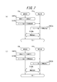
- FIG. 7 (a) shows operations of base station 10a and mobile station 11a of communication system 1 according to Embodiment 1 of the present invention.
- the base station control unit 103a allocates the used downlink radio resources and the used uplink radio resources, which are part of the carrier A, to the mobile station 11a (and other mobile stations connected to the base station 10a) (step S101a).
- the used downlink radio resources are allocated by distributed RB allocation.
- the base station control unit 103a allocates the PDSCH to the user data areas of the RBs from the 0th to the 23rd in the downlink. Further, the base station control unit 103a assigns a reference signal to a subcarrier different from the base station 10b. In addition, the base station control unit 103a adjusts the cell ID and avoids an overlapping portion, and allocates PCFICH and PHICH to the control information area. In addition, after allocating PCFICH and PHICH, the base station control unit 103a performs interleaving and sequentially allocates PDCCH to radio resources to which PCFICH and PHICH are not allocated from the low frequency side.
- the base station control unit 103a transmits the assigned downlink radio resource and uplink uplink resource allocation information to the mobile station 11a (and other mobile stations connected to the base station 10a) via the base station communication unit 101a. (Step S102a). The mobile station 11a receives the information (step S103a).
- the base station control unit 103a communicates with the mobile station 11a through the base station communication unit 101a and the base station baseband unit 102a (step S104a).
- the base station control unit 103a does not transmit the PDCCH in the RE in which the PDCCH of the own station collides with the reference signal of the base station 10b in the downlink.
- FIG. 7B shows operations of the base station 10b and the mobile station 11b.
- the base station control unit 103a allocates the used downlink radio resources and the used uplink radio resources, which are part of the carrier B, to the mobile station 11b (and other mobile stations connected to the base station 10b) (step S101b). .
- the base station control unit 103b allocates the PDSCH to the user data areas of the RBs Nos. 24 to 44 in the downlink by local RB allocation.
- the base station control unit 103b assigns a reference signal to a subcarrier different from the base station 10a.
- the base station control unit 103b adjusts the cell ID to avoid overlapping portions or the control channel (PDCCH) of the base station 10a and allocates PCFICH and PHICH to the control information area.
- the base station control unit 103b allocates PDCCH to radio resources to which PCFICH and PHICH are not allocated.
- the base station control unit 103b assigns the assigned downlink radio resource and uplink radio resource assignment information to the mobile station 11b (and other mobile stations connected to the base station 10b) via the base station communication unit 101b. ) (Step S102b).
- the mobile station 11b receives the information (step S103b).
- the base station control unit 103b communicates with the mobile station 11b through the base station communication unit 101b and the base station baseband unit 102b (step S104b).
- one communication apparatus performs the other communication apparatus (base station 10a) with respect to PDSCH allocation.
- a part of the radio resource of the overlapping part is used in preference to the station 10b). For this reason, it is possible to secure the carrier bandwidth and increase the communication speed, and prevent the radio wave interference with other systems by placing the carrier in the frequency band assigned to the communication method.
- the base station 10a and the base station 10b transmit reference signals by using radio resources that do not collide with each other in overlapping portions, that is, by using different subcarriers with respect to allocation of reference signals.
- the base station 10b uses radio resources that do not collide with the control channel of the base station 10a, that is, PDCCH, PCFICH, and PHICH, for allocation of PCFICH and PHICH. For this reason, it is possible to avoid the PCFICH and PHICH colliding with the control channel of the base station 10a and improve the stability of communication.
- the base station 10b according to the modification uses the radio resources in the control signal area and does not use the radio resources in the user data area with an arrangement different from that of the base station 10a regarding the allocation of the reference signal in the overlapping portion.
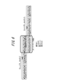
- FIG. 8 is a diagram showing details of RBs 19 and 20 in FIG.
- the 19th RB which is not an overlapping part is the same as that in the first embodiment.
- the reference signal of the base station 10b is assigned to the head symbol of the 20th RB that is the overlapping part.
- the reference signal of the base station 10b is not allocated to the user data area, and more PDSCHs of the base station 10a are allocated compared to the first embodiment.
- the base station 10b is configured to transmit the reference signal in the overlapping portion with a radio signal in the control signal region by an arrangement different from the base station 10a.
- the stability of communication can be improved.
- the base station 10a can transmit user data more efficiently by allocating the PDSCH of the base station 10a as much as the base station 10b does not allocate the reference signal to the overlapping user data area.
- Embodiment 2 Next, a second embodiment of the present invention will be described.
- the same components as those in the first embodiment are denoted by the same reference numerals and description thereof is omitted.
- the communication system 1 according to Embodiment 2 changes the radio resource allocation method according to the MCS of the mobile station connected to the base station.
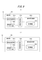
- FIG. 9 is a block diagram of base station 10a and base station 10b according to Embodiment 2 of the present invention.
- the base station 10a includes a base station communication unit 101a, a base station baseband unit 102a, a base station control unit 103a, and a base station storage unit 104a.
- the base station communication unit 101a and the base station baseband unit 102a are the same as those in the first embodiment, and a description thereof will be omitted.
- the base station storage unit 104a stores the MCS threshold value 105a in advance.
- the MCS threshold 105a is a degradation of the MSCH threshold (first threshold) used by the base station control unit 103a in radio resource allocation to each mobile station connected to the base station 10a and the PDSCH BLER characteristic for one mobile station.
- MCS threshold (second threshold) for the ratio of collision RBs not to be included.
- the second threshold value can be calculated in advance by simulation.
- the base station control unit 103a determines whether or not to transmit the PDSCH based on the MCS of the mobile station 11a in a part of the PDSCH assigned to the overlapping part. Specifically, when the MCS of the mobile station 11a is equal to or greater than the second threshold, the base station control unit 103a transmits the PDSCH with an RE that collides with the reference signal of the base station 10b in the overlapping user data area. And notifies the base station 10b to that effect. On the other hand, when the MCS of the mobile station 11a is less than the second threshold, the base station control unit 103a determines not to transmit PDSCH using the RE, and notifies the base station 10b to that effect.
- the base station 10b includes a base station communication unit 101b, a base station baseband unit 102b, a base station control unit 103b, and a base station storage unit 104b.
- the base station communication unit 101b and the base station baseband unit 102b are the same as those in the first embodiment, and a description thereof will be omitted.
- the base station storage unit 104b stores the MCS threshold value 105b in advance.
- the MCS threshold 105b includes an MCS threshold (first threshold) used by the base station control unit 103b in radio resource allocation to each mobile station connected to the base station 10b.
- the base station control unit 103b determines whether or not to transmit a reference signal in the overlapping user data area based on the notification from the base station 10a. Specifically, when the base station control unit 103b receives a notification that the base station 10a transmits the PDSCH in an RE that collides with the reference signal of the base station 10b in the overlapping user data area, the base station control unit 103b refers to the RE. Decide not to send a signal. On the other hand, when the base station control unit 103b receives a notification indicating that the base station 10a does not transmit the PDSCH at the RE, the base station control unit 103b determines to transmit a reference signal at the RE.
- FIG. 10 shows an operation in which the base station allocates radio resources based on the MCS of the mobile station in the communication system 1 according to Embodiment 2 of the present invention.
- the base station 10a receives a CQI report from the mobile station 11a (step S201).
- the base station 10a determines the MCS of the mobile station 11a based on the CQI extracted from the received CQI report (step S202).
- the base station 10a determines the RB allocation priority for the mobile station 11a. Specifically, when the MCS value determined in step S202 is equal to or greater than the first threshold, the base station 10a lowers the allocation priority for overlapping RBs.
- the base station 10a determines whether or not the MCS determined in step S202 is greater than or equal to the second threshold (step S204).
- the base station 10a determines to transmit the PDSCH with an RE that collides with the reference signal of the base station 10b in the overlapping user data area (step S204). S205).
- the base station 10a notifies the base station 10b that the PDSCH is transmitted using the RE (step S206).
- the base station 10b determines not to transmit the reference signal by the RE (step S207).
- the base station 10a determines not to transmit the PDSCH with an RE that collides with the reference signal of the base station 10b in the overlapping user data area. (Step S208).
- the base station 10a notifies the base station 10b that the PDSCH is not transmitted by the RE (step S209).
- the base station 10b determines to transmit a reference signal using the RE (step S210).
- the base station 10a and the base station 10b can use any of the REs in which the PDSCH (user data) of the base station 10a and the reference signal of the base station 10b collide with each other in the overlapping user data area according to the MCS of the mobile station 11a. Decide which station will use.
- the base station 10a and the base station 10b preferentially transmit the PDSCH when the MCS is large, and the base station 10b preferentially transmits the reference signal when the MCS is small. For this reason, the stability of communication can be improved as the communication system 1 as a whole.
- the communication system 1 uses the second frequency band of 9 MHz.
- the present invention is not limited to this, and the second frequency band may be a band less than 9 MHz or more than 9 MHz. .
- the bandwidth of the second frequency band according to the bandwidth of the second frequency band, the bandwidth of the first frequency band and the bandwidth of overlapping portions of a plurality of carriers are appropriately changed.
- the priority assigned to the RB of the overlapping portion is reduced. You may make it raise the priority assigned to RBs other than a part.
Landscapes
- Engineering & Computer Science (AREA)
- Signal Processing (AREA)
- Computer Networks & Wireless Communication (AREA)
- Quality & Reliability (AREA)
- Mobile Radio Communication Systems (AREA)
Abstract
La présente invention concerne un système de communication, des stations de base, et un procédé de contrôle de communications qui permettent d'augmenter la vitesse de communication dans des systèmes de communication tels que des TD-LTE, en garantissant les bandes passantes porteuses, et d'empêcher les interférences par ondes radio avec d'autres systèmes, en plaçant des porteuses sur une bande de fréquences (une bande de 9 MHz, par exemple) affectée au système de communication. Le système de communication (1) est muni d'une pluralité de stations de base qui, lorsque les porteuses d'une première bande passante de fréquences sont agencées en série, assurent une communication sans fil en plaçant une pluralité de porteuses sur une seconde bande de fréquences prédéterminée supérieure à la bande passante de la seconde bande de fréquences. Le système de communication (1) place une partie de chaque porteuse de façon à chevaucher la seconde bande de fréquences. Une première station de base (10a) qui utilise une porteuse (A), qui est placée de façon à être partiellement en chevauchement, utilise de préférence une partie des ressources sans fil de la partie en chevauchement sur une seconde station de base (10b) qui utilise une autre porteuse (B), en relation avec l'affectation de données utilisateur.
Priority Applications (1)
| Application Number | Priority Date | Filing Date | Title |
|---|---|---|---|
| US14/894,493 US10499395B2 (en) | 2013-05-29 | 2014-05-29 | Communication system, base station, and communication control method |
Applications Claiming Priority (4)
| Application Number | Priority Date | Filing Date | Title |
|---|---|---|---|
| JP2013113118A JP6222995B2 (ja) | 2013-05-29 | 2013-05-29 | 通信システム、基地局、及び通信制御方法 |
| JP2013113174A JP6222996B2 (ja) | 2013-05-29 | 2013-05-29 | 通信システム、基地局、及び通信制御方法 |
| JP2013-113118 | 2013-05-29 | ||
| JP2013-113174 | 2013-05-29 |
Publications (1)
| Publication Number | Publication Date |
|---|---|
| WO2014192305A1 true WO2014192305A1 (fr) | 2014-12-04 |
Family
ID=51988356
Family Applications (1)
| Application Number | Title | Priority Date | Filing Date |
|---|---|---|---|
| PCT/JP2014/002857 Ceased WO2014192305A1 (fr) | 2013-05-29 | 2014-05-29 | Système de communication, stations de base, et procédé de contrôle de communications |
Country Status (2)
| Country | Link |
|---|---|
| US (1) | US10499395B2 (fr) |
| WO (1) | WO2014192305A1 (fr) |
Families Citing this family (11)
| Publication number | Priority date | Publication date | Assignee | Title |
|---|---|---|---|---|
| US10271342B2 (en) * | 2013-08-07 | 2019-04-23 | Telefonaktiebolaget Lm Ericsson (Publ) | Allocating feedback resources for carrier aggregation |
| US9548848B1 (en) * | 2015-02-19 | 2017-01-17 | Mbit Wireless, Inc. | Method and apparatus for reduced complexity CQI feedback in wireless communication systems |
| JP6174640B2 (ja) * | 2015-08-11 | 2017-08-02 | 京セラ株式会社 | 基地局および無線通信方法 |
| CN108632005B (zh) * | 2017-03-24 | 2023-12-15 | 华为技术有限公司 | 一种参考信号传输方法、装置及系统 |
| US11659504B2 (en) * | 2017-10-06 | 2023-05-23 | Ntt Docomo, Inc. | Terminal, radio communication method, and base station |
| US11445487B2 (en) | 2018-06-15 | 2022-09-13 | At&T Intellectual Property I, L.P. | Single user super position transmission for future generation wireless communication systems |
| US11140668B2 (en) | 2018-06-22 | 2021-10-05 | At&T Intellectual Property I, L.P. | Performance of 5G MIMO |
| US10945281B2 (en) | 2019-02-15 | 2021-03-09 | At&T Intellectual Property I, L.P. | Facilitating improved performance of multiple downlink control channels in advanced networks |
| US12250050B2 (en) * | 2021-07-30 | 2025-03-11 | Apple Inc. | Beam selection refinement for wireless communication in static conditions |
| US12414099B2 (en) | 2021-07-30 | 2025-09-09 | Apple Inc. | Sensor-assisted millimeter-wave beam management |
| US20250294537A1 (en) * | 2022-04-27 | 2025-09-18 | Telefonaktiebolaget Lm Ericsson (Publ) | Network deployment based on partially overlapped carriers |
Citations (5)
| Publication number | Priority date | Publication date | Assignee | Title |
|---|---|---|---|---|
| JP2008017318A (ja) * | 2006-07-07 | 2008-01-24 | Fujitsu Ltd | 移動局装置、無線基地局装置及び無線通信システム |
| JP2011101122A (ja) * | 2009-11-04 | 2011-05-19 | Kyocera Corp | 移動通信システム、移動局、基地局、およびハンドオーバ方法 |
| JP2011151499A (ja) * | 2010-01-19 | 2011-08-04 | National Institute Of Information & Communication Technology | Mimo−ofdmシステムにおける無線リソース割り当て方法,及び無線リソース割り当て装置 |
| WO2012073371A1 (fr) * | 2010-12-02 | 2012-06-07 | 富士通株式会社 | Système de communication sans fil, station de base, station mobile et procédé de communication sans fil |
| WO2014119246A1 (fr) * | 2013-01-29 | 2014-08-07 | 京セラ株式会社 | Système, procédé et appareil de communication |
Family Cites Families (8)
| Publication number | Priority date | Publication date | Assignee | Title |
|---|---|---|---|---|
| CN100342749C (zh) * | 2001-05-25 | 2007-10-10 | 株式会社Ntt都科摩 | 一种信道分配方法及通信控制装置 |
| WO2010088970A1 (fr) * | 2009-02-09 | 2010-08-12 | Nokia Siemens Networks Oy | Appareil de gestion de l'exploitation d'un spectre, utilisant des largeurs de bande de canal se chevauchant |
| US9036518B2 (en) * | 2009-03-17 | 2015-05-19 | Nec Corporation | Wireless base station apparatus, wireless communication system, wireless communication method, and program |
| US9271167B2 (en) * | 2010-04-13 | 2016-02-23 | Qualcomm Incorporated | Determination of radio link failure with enhanced interference coordination and cancellation |
| US9209955B2 (en) * | 2011-10-11 | 2015-12-08 | Qualcomm Incorporated | Extension carrier as a bandwidth extension |
| US8982693B2 (en) * | 2012-05-14 | 2015-03-17 | Google Technology Holdings LLC | Radio link monitoring in a wireless communication device |
| EP2984884A1 (fr) * | 2013-04-08 | 2016-02-17 | Telefonaktiebolaget LM Ericsson (publ) | Exécution de mesures inter-fréquences sur des porteuses ayant des bandes passantes se chevauchant |
| KR101706195B1 (ko) * | 2013-04-11 | 2017-02-15 | 한국전자통신연구원 | 다중 반송파 및 이종망 통합 무선 액세스 환경에서의 무선 자원 관리 방법 및 그 장치 |
-
2014
- 2014-05-29 US US14/894,493 patent/US10499395B2/en active Active
- 2014-05-29 WO PCT/JP2014/002857 patent/WO2014192305A1/fr not_active Ceased
Patent Citations (5)
| Publication number | Priority date | Publication date | Assignee | Title |
|---|---|---|---|---|
| JP2008017318A (ja) * | 2006-07-07 | 2008-01-24 | Fujitsu Ltd | 移動局装置、無線基地局装置及び無線通信システム |
| JP2011101122A (ja) * | 2009-11-04 | 2011-05-19 | Kyocera Corp | 移動通信システム、移動局、基地局、およびハンドオーバ方法 |
| JP2011151499A (ja) * | 2010-01-19 | 2011-08-04 | National Institute Of Information & Communication Technology | Mimo−ofdmシステムにおける無線リソース割り当て方法,及び無線リソース割り当て装置 |
| WO2012073371A1 (fr) * | 2010-12-02 | 2012-06-07 | 富士通株式会社 | Système de communication sans fil, station de base, station mobile et procédé de communication sans fil |
| WO2014119246A1 (fr) * | 2013-01-29 | 2014-08-07 | 京セラ株式会社 | Système, procédé et appareil de communication |
Also Published As
| Publication number | Publication date |
|---|---|
| US10499395B2 (en) | 2019-12-03 |
| US20160119926A1 (en) | 2016-04-28 |
Similar Documents
| Publication | Publication Date | Title |
|---|---|---|
| CN115918014B (zh) | Coreset和搜索空间与资源带宽的关联 | |
| US10887068B2 (en) | Methods and apparatus for an extensible and scalable control channel for wireless networks | |
| CN116530040B (zh) | 用于侧行链路通信的长物理侧行链路共享信道格式 | |
| EP3556174B1 (fr) | Indication de signal pour coexistence souple nouvelle radio (nr) / évolution à long terme (lte) | |
| US10897764B2 (en) | Radio-unlicensed (NR-U) interlace-based resource allocations | |
| KR102636342B1 (ko) | 무선 통신 시스템을 위한 하향링크 제어 채널 송수신 방법 및 장치 | |
| US8619687B2 (en) | Coordinating uplink resource allocation | |
| JP5969592B2 (ja) | サブフレームの制御領域を調整して無線通信システムにおけるチャネル間の干渉を低減する方法および装置 | |
| EP4152677A1 (fr) | Programmation dans des systèmes de communication avec de multiples types de services | |
| US10602392B2 (en) | Wireless communication method and wireless communication apparatus | |
| US10499395B2 (en) | Communication system, base station, and communication control method | |
| JP5847525B2 (ja) | 無線通信端末、基地局装置、無線通信システム及び無線通信方法 | |
| US20180084398A1 (en) | User equipment and method for packet based device-to-device (d2d) discovery in an lte network | |
| EP3133848B1 (fr) | Équipement utilisateur pour la découverte dispositif-dispositif (d2d) basée sur paquet dans un réseau lte | |
| US9668266B2 (en) | Interference control in HETNETs | |
| KR20140010383A (ko) | 마이크로 기지국, 유저단말 및 무선통신방법 | |
| JPWO2018155619A1 (ja) | ユーザ端末及び無線通信方法 | |
| CN108496388A (zh) | 基站装置、终端装置以及通信方法 | |
| JP2017513289A (ja) | 端末装置、基地局装置、通信システム、通信方法、および集積回路 | |
| JP2014216698A (ja) | 通信制御装置、通信制御方法、無線通信システム及び端末装置 | |
| WO2018155605A1 (fr) | Terminal utilisateur et procédé de communication radio | |
| JP6222995B2 (ja) | 通信システム、基地局、及び通信制御方法 | |
| JP5227936B2 (ja) | 移動通信方法、移動局及び無線基地局 | |
| JP6222996B2 (ja) | 通信システム、基地局、及び通信制御方法 | |
| WO2024168687A1 (fr) | Procédé et appareil de communication de liaison latérale, dispositif et support d'enregistrement |
Legal Events
| Date | Code | Title | Description |
|---|---|---|---|
| 121 | Ep: the epo has been informed by wipo that ep was designated in this application |
Ref document number: 14803954 Country of ref document: EP Kind code of ref document: A1 |
|
| WWE | Wipo information: entry into national phase |
Ref document number: 14894493 Country of ref document: US |
|
| NENP | Non-entry into the national phase |
Ref country code: DE |
|
| 122 | Ep: pct application non-entry in european phase |
Ref document number: 14803954 Country of ref document: EP Kind code of ref document: A1 |