WO2014192381A1 - Co2回収装置及びco2回収方法 - Google Patents
Co2回収装置及びco2回収方法 Download PDFInfo
- Publication number
- WO2014192381A1 WO2014192381A1 PCT/JP2014/057557 JP2014057557W WO2014192381A1 WO 2014192381 A1 WO2014192381 A1 WO 2014192381A1 JP 2014057557 W JP2014057557 W JP 2014057557W WO 2014192381 A1 WO2014192381 A1 WO 2014192381A1
- Authority
- WO
- WIPO (PCT)
- Prior art keywords
- aqueous solution
- basic aqueous
- regenerator
- heat
- inorganic powder
- Prior art date
- Legal status (The legal status is an assumption and is not a legal conclusion. Google has not performed a legal analysis and makes no representation as to the accuracy of the status listed.)
- Ceased
Links
Images


Classifications
-
- C—CHEMISTRY; METALLURGY
- C01—INORGANIC CHEMISTRY
- C01B—NON-METALLIC ELEMENTS; COMPOUNDS THEREOF; METALLOIDS OR COMPOUNDS THEREOF NOT COVERED BY SUBCLASS C01C
- C01B32/00—Carbon; Compounds thereof
- C01B32/50—Carbon dioxide
-
- B—PERFORMING OPERATIONS; TRANSPORTING
- B01—PHYSICAL OR CHEMICAL PROCESSES OR APPARATUS IN GENERAL
- B01D—SEPARATION
- B01D53/00—Separation of gases or vapours; Recovering vapours of volatile solvents from gases; Chemical or biological purification of waste gases, e.g. engine exhaust gases, smoke, fumes, flue gases, aerosols
- B01D53/14—Separation of gases or vapours; Recovering vapours of volatile solvents from gases; Chemical or biological purification of waste gases, e.g. engine exhaust gases, smoke, fumes, flue gases, aerosols by absorption
- B01D53/1425—Regeneration of liquid absorbents
-
- B—PERFORMING OPERATIONS; TRANSPORTING
- B01—PHYSICAL OR CHEMICAL PROCESSES OR APPARATUS IN GENERAL
- B01D—SEPARATION
- B01D53/00—Separation of gases or vapours; Recovering vapours of volatile solvents from gases; Chemical or biological purification of waste gases, e.g. engine exhaust gases, smoke, fumes, flue gases, aerosols
- B01D53/14—Separation of gases or vapours; Recovering vapours of volatile solvents from gases; Chemical or biological purification of waste gases, e.g. engine exhaust gases, smoke, fumes, flue gases, aerosols by absorption
- B01D53/1456—Removing acid components
- B01D53/1475—Removing carbon dioxide
-
- B—PERFORMING OPERATIONS; TRANSPORTING
- B01—PHYSICAL OR CHEMICAL PROCESSES OR APPARATUS IN GENERAL
- B01D—SEPARATION
- B01D53/00—Separation of gases or vapours; Recovering vapours of volatile solvents from gases; Chemical or biological purification of waste gases, e.g. engine exhaust gases, smoke, fumes, flue gases, aerosols
- B01D53/34—Chemical or biological purification of waste gases
- B01D53/46—Removing components of defined structure
- B01D53/62—Carbon oxides
-
- B—PERFORMING OPERATIONS; TRANSPORTING
- B01—PHYSICAL OR CHEMICAL PROCESSES OR APPARATUS IN GENERAL
- B01D—SEPARATION
- B01D53/00—Separation of gases or vapours; Recovering vapours of volatile solvents from gases; Chemical or biological purification of waste gases, e.g. engine exhaust gases, smoke, fumes, flue gases, aerosols
- B01D53/34—Chemical or biological purification of waste gases
- B01D53/96—Regeneration, reactivation or recycling of reactants
-
- B—PERFORMING OPERATIONS; TRANSPORTING
- B01—PHYSICAL OR CHEMICAL PROCESSES OR APPARATUS IN GENERAL
- B01D—SEPARATION
- B01D2252/00—Absorbents, i.e. solvents and liquid materials for gas absorption
- B01D2252/20—Organic absorbents
- B01D2252/204—Amines
- B01D2252/20431—Tertiary amines
-
- B—PERFORMING OPERATIONS; TRANSPORTING
- B01—PHYSICAL OR CHEMICAL PROCESSES OR APPARATUS IN GENERAL
- B01D—SEPARATION
- B01D2252/00—Absorbents, i.e. solvents and liquid materials for gas absorption
- B01D2252/20—Organic absorbents
- B01D2252/204—Amines
- B01D2252/20478—Alkanolamines
-
- B—PERFORMING OPERATIONS; TRANSPORTING
- B01—PHYSICAL OR CHEMICAL PROCESSES OR APPARATUS IN GENERAL
- B01D—SEPARATION
- B01D2252/00—Absorbents, i.e. solvents and liquid materials for gas absorption
- B01D2252/20—Organic absorbents
- B01D2252/204—Amines
- B01D2252/20478—Alkanolamines
- B01D2252/20484—Alkanolamines with one hydroxyl group
-
- B—PERFORMING OPERATIONS; TRANSPORTING
- B01—PHYSICAL OR CHEMICAL PROCESSES OR APPARATUS IN GENERAL
- B01D—SEPARATION
- B01D2252/00—Absorbents, i.e. solvents and liquid materials for gas absorption
- B01D2252/20—Organic absorbents
- B01D2252/204—Amines
- B01D2252/20478—Alkanolamines
- B01D2252/20489—Alkanolamines with two or more hydroxyl groups
-
- B—PERFORMING OPERATIONS; TRANSPORTING
- B01—PHYSICAL OR CHEMICAL PROCESSES OR APPARATUS IN GENERAL
- B01D—SEPARATION
- B01D2255/00—Catalysts
- B01D2255/20—Metals or compounds thereof
- B01D2255/207—Transition metals
- B01D2255/20738—Iron
-
- B—PERFORMING OPERATIONS; TRANSPORTING
- B01—PHYSICAL OR CHEMICAL PROCESSES OR APPARATUS IN GENERAL
- B01D—SEPARATION
- B01D2255/00—Catalysts
- B01D2255/20—Metals or compounds thereof
- B01D2255/207—Transition metals
- B01D2255/20761—Copper
-
- B—PERFORMING OPERATIONS; TRANSPORTING
- B01—PHYSICAL OR CHEMICAL PROCESSES OR APPARATUS IN GENERAL
- B01D—SEPARATION
- B01D2255/00—Catalysts
- B01D2255/40—Mixed oxides
-
- B—PERFORMING OPERATIONS; TRANSPORTING
- B01—PHYSICAL OR CHEMICAL PROCESSES OR APPARATUS IN GENERAL
- B01D—SEPARATION
- B01D2255/00—Catalysts
- B01D2255/50—Zeolites
-
- B—PERFORMING OPERATIONS; TRANSPORTING
- B01—PHYSICAL OR CHEMICAL PROCESSES OR APPARATUS IN GENERAL
- B01D—SEPARATION
- B01D2255/00—Catalysts
- B01D2255/70—Non-metallic catalysts, additives or dopants
-
- B—PERFORMING OPERATIONS; TRANSPORTING
- B01—PHYSICAL OR CHEMICAL PROCESSES OR APPARATUS IN GENERAL
- B01D—SEPARATION
- B01D2257/00—Components to be removed
- B01D2257/50—Carbon oxides
- B01D2257/504—Carbon dioxide
-
- Y—GENERAL TAGGING OF NEW TECHNOLOGICAL DEVELOPMENTS; GENERAL TAGGING OF CROSS-SECTIONAL TECHNOLOGIES SPANNING OVER SEVERAL SECTIONS OF THE IPC; TECHNICAL SUBJECTS COVERED BY FORMER USPC CROSS-REFERENCE ART COLLECTIONS [XRACs] AND DIGESTS
- Y02—TECHNOLOGIES OR APPLICATIONS FOR MITIGATION OR ADAPTATION AGAINST CLIMATE CHANGE
- Y02C—CAPTURE, STORAGE, SEQUESTRATION OR DISPOSAL OF GREENHOUSE GASES [GHG]
- Y02C20/00—Capture or disposal of greenhouse gases
- Y02C20/40—Capture or disposal of greenhouse gases of CO2
-
- Y—GENERAL TAGGING OF NEW TECHNOLOGICAL DEVELOPMENTS; GENERAL TAGGING OF CROSS-SECTIONAL TECHNOLOGIES SPANNING OVER SEVERAL SECTIONS OF THE IPC; TECHNICAL SUBJECTS COVERED BY FORMER USPC CROSS-REFERENCE ART COLLECTIONS [XRACs] AND DIGESTS
- Y02—TECHNOLOGIES OR APPLICATIONS FOR MITIGATION OR ADAPTATION AGAINST CLIMATE CHANGE
- Y02P—CLIMATE CHANGE MITIGATION TECHNOLOGIES IN THE PRODUCTION OR PROCESSING OF GOODS
- Y02P20/00—Technologies relating to chemical industry
- Y02P20/151—Reduction of greenhouse gas [GHG] emissions, e.g. CO2
Definitions
- the present invention relates to a CO 2 recovery device and a CO 2 recovery method for recovering CO 2 absorbed in an amine solution.
- a chemical absorption method is known as a method for removing and recovering CO 2 contained in combustion exhaust gas from thermal power plants and steel plants.
- a conventional apparatus for recovering CO 2 by a chemical absorption method generally includes an absorption tower and a regeneration tower (for example, Patent Document 1).
- CO 2 is absorbed in an aqueous solution of an amine compound at 40 to 50 ° C. (hereinafter referred to as an amine solution).
- the amine liquid in which CO 2 has been absorbed (hereinafter, rich liquid) is sent to the regeneration tower.
- the regeneration tower is modeled on a general distillation tower, and the rich liquid dripped inside the regeneration tower is brought into contact with the rising vapor so that the rich liquid is heated.
- the apparatus system of Patent Document 2 has a low-temperature regeneration tower whose regeneration temperature is 100 ° C., for example, and a high-temperature regeneration tower whose regeneration temperature is 120 ° C., for example.
- CO 2 can be recovered with less energy overall than a system having only a regeneration tower having a regeneration temperature of 120 ° C.
- the system of Patent Document 2 requires a 120 ° C. heat source used in the high-temperature regeneration tower.
- the amine solution is heated at a high temperature steam as described in Patent Documents 1 and 2
- the vapor containing CO 2 separated from the amine solution amine solution after CO 2 separation becomes high. For this reason, sensible heat / latent heat loss due to cooling of steam-containing CO 2 and sensible heat loss due to amine liquid cooling are large.
- the CO 2 recovery apparatus uses a general distillation tower as a model for the regeneration tower.
- the regeneration energy (recovered energy) per unit CO 2 is reduced by increasing the CO 2 desorption amount (recovered amount) in the regeneration tower.
- the amine liquid in the reboiler is boiled to generate high-temperature steam, the steam is introduced from the lower part of the regeneration tower, and is brought into contact with the amine liquid dripped from the upper part. It has been considered desirable to maintain the amine solution at a high temperature.
- the amine liquid temperature in a reboiler was adjusted to about 120 degreeC using the comparatively high-quality heat medium (about 120 degreeC) in many cases. This is because development has been carried out on the premise of using a distillation tower type regeneration tower, and until now, no development focusing on reducing the reboiler temperature (regeneration temperature) has been conducted.
- the present invention has been made in view of the above matters, and an object of the present invention is to provide a CO 2 recovery apparatus and a CO 2 recovery method capable of recovering CO 2 using relatively low-grade heat of 100 ° C. or lower. Is to provide.
- CO 2 recovery apparatus an absorbing portion for absorbing the CO 2 in the basic aqueous solution, a basic aqueous solution from which CO 2 has been absorbed, and heated using the following thermal medium 100 ° C. And a regeneration unit for desorbing the steam-containing CO 2 .
- a heat exchanger that performs heat exchange between the basic aqueous solution in which the CO 2 has been absorbed and the basic aqueous solution from which the vapor-containing CO 2 has been desorbed, and the basic solution from which the vapor-containing CO 2 has been desorbed after the aqueous solution has passed through the heat exchanger, a cooler for cooling the said basic aqueous solution 50 ° C. or less, by cooling the vapor containing CO 2, and a cooling device for removing moisture from the steam containing CO 2 Further prepare.
- the heat medium is water.
- the basic aqueous solution is an alkanolamine aqueous solution.
- the alkanolamine aqueous solution is an aqueous solution mainly composed of a tertiary amine solution or a highly sterically hindered amine solution, and is an aqueous solution formed by combining any one or more of these.
- the steam-containing CO 2 is desorbed by heating with a heat medium of 100 ° C. or less by a regenerator having a multi-tube heat exchanger structure.
- the regenerator includes a regenerator that holds a basic aqueous solution, a heat exchanger that heats the basic aqueous solution with a heat medium of 100 ° C. or less, and a basic unit between the regenerator and the heat exchanger.
- a system that circulates an aqueous solution, and the system supplies a basic aqueous solution whose temperature has decreased due to desorption of CO 2 in the regenerator to the heat exchanger, and in the heat exchanger A basic aqueous solution supplemented with heat by heating with a heat medium is supplied to the regenerator.
- either one or both of the portion where the basic aqueous solution is present in the regenerator and the flow path through which the basic aqueous solution passes in the regeneration unit is formed with inorganic powder or inorganic powder.
- the catalyst which consists of a body is arrange
- the BET specific surface area of the molded object of the said inorganic powder or an inorganic powder is 7 m ⁇ 2 > / g or more.
- the catalyst composed of the inorganic powder or the molded body of the inorganic powder is one or a combination of two or more of a zeolite catalyst and an alumina catalyst.
- CO 2 recovery method the absorption step of absorbing CO 2 in the basic aqueous solution, a basic aqueous solution from which CO 2 has been absorbed, and heated using the following thermal medium 100 ° C. And a regeneration step for desorbing the steam-containing CO 2 .
- heat exchange is performed in the heat exchange step in which heat exchange is performed between the basic aqueous solution in which the CO 2 is absorbed and the basic aqueous solution in which the vapor-containing CO 2 is desorbed, and the heat exchange is performed in the heat exchange step.
- the heat medium is water.
- the basic aqueous solution is an alkanolamine aqueous solution.
- the alkanolamine aqueous solution is an aqueous solution mainly composed of a tertiary amine solution or a highly sterically hindered amine solution, and is an aqueous solution formed by combining any one or more of these.
- a regenerator having a multi-tube heat exchanger structure heats the basic aqueous solution in which the CO 2 has been absorbed using a heat medium of 100 ° C. or less to remove the steam-containing CO 2 . Let go.
- CO 2 is desorbed in a regenerator having a basic aqueous solution, and the basic aqueous solution whose temperature has decreased due to desorption is heated in a heat exchanger with a heat medium of 100 ° C. or less. Then, the basic aqueous solution is replenished with heat, and the basic aqueous solution supplemented with the heat is supplied again to the regenerator to desorb the vapor-containing CO 2 .
- either one or both of the portion where the basic aqueous solution exists in the regenerator and the flow path through which the basic aqueous solution passes in the regenerator are formed with an inorganic powder or an inorganic powder molded body.
- the inorganic powder or the compact of the inorganic powder has a BET specific surface area of 7 m 2 / g or more.
- the catalyst composed of the inorganic powder or the molded body of the inorganic powder is one or a combination of two or more of a zeolite catalyst and an alumina catalyst.
- the heat supply to the basic aqueous solution uses a heat medium of 100 ° C. or less.
- low-grade heat such as a heat source of 100 ° C. or less
- unused exhaust heat energy in power plants, steelworks, and other industries can be used. From the above, according to the present invention, CO 2 can be recovered using low-grade heat.
- the steam-containing CO 2 Only CO 2 is recovered from the steam. For this reason, CO 2 can be recovered.
- the following (1) due to the recovery of CO 2 can be kept low respectively waste heat of (2).
- (2) Exhaust heat amount when cooling the steam-containing CO 2 That is, for (1), by using the heat medium of 100 ° C. or less, the steam-containing CO
- the basic aqueous solution after 2 is desorbed has a lower temperature than when high temperature steam is used. Therefore, it is possible to reduce the amount of exhaust heat in the cooling step before introducing the basic aqueous solution after the vapor-containing CO 2 is desorbed into the absorption tower.
- the amount of exhaust heat accompanying CO 2 recovery can be kept low, and as a result, the thermal energy required for CO 2 recovery can be kept low.
- FIG. 1 is a schematic diagram 1 schematically showing an embodiment of a CO 2 desorption apparatus according to a first embodiment of the present invention. It is sectional drawing which shows the heat exchanger which can be used as a regenerator in FIG.
- An embodiment of the CO 2 elimination device according to a second embodiment of the present invention is a schematic diagram 2 illustrating schematically.
- FIG. 1 is a schematic diagram showing a CO 2 recovery apparatus 1 according to the first embodiment.
- the CO 2 recovery apparatus 1 according to the first embodiment removes and recovers CO 2 contained in exhaust gas using a basic aqueous solution.
- the basic aqueous solution used in the first embodiment is an alkanolamine aqueous solution (hereinafter referred to as an amine solution) based on alkanolamine.
- the amine solution is preferably a tertiary amine solution or an aqueous solution mainly composed of an amine solution having a large steric hindrance, and any one or a combination of these can be used.
- the tertiary amine include 2-dimethylaminoethanol, N-methyldiethanolamine, and triethylenediamine.
- An amine solution having a large steric hindrance is an amine solution in which a plurality of functional groups of alkyl groups, hydroxyl groups, and amino groups are bonded to one or more C atoms adjacent to the N atom, such as 2-isopropylaminoethanol. (IPAE) and 2-tert-butylaminoethanol (t-BAE), but are not limited thereto.
- An aqueous solution mainly composed of a tertiary amine solution or an amine solution having a large steric hindrance may have a hydroxyl group (—OH group) or an ether group (—O—), and has a cyclic structure. May be.
- aqueous solution containing a tertiary amine solution or an amine solution having a large steric hindrance as a main component is shown below.
- CO 2 in an amine solution exists as a main form as a carbamate ion bonded to an N atom of an amine molecule or as a bicarbonate ion, but in a tertiary amine, CO 2 exists as a bicarbonate ion as a main form.
- the amine solution having a large steric hindrance it exists as a bicarbonate ion as a main form rather than a carbamate ion.
- the CO 2 recovery device 1 is roughly divided into an absorption unit 2 and a regeneration unit 3.
- exhaust gas is introduced from the boiler.
- the exhaust gas contains CO 2 , N 2 , H 2 O, and O 2 .
- CO 2 contained in the exhaust gas is absorbed and removed by the amine liquid.
- the amine liquid in which CO 2 has been absorbed (hereinafter, rich liquid) is sent to the regeneration unit 3 through lines L1 and L2.
- the line L1 is provided with an absorption liquid extraction pump 11 that pumps the rich liquid.
- the rich liquid is heated using a heat medium of 100 ° C. or lower.
- CO 2 containing vapor is desorbed from the rich liquid.
- water is used as the heat medium, but steam or a water-steam mixture may be used.
- An oil medium such as silicon oil can also be used.
- the amine liquid after the vapor-containing CO 2 has been desorbed (those from which the vapor-containing CO 2 has been desorbed from the rich liquid: hereinafter, lean liquid) is supplied through the lines L3 and L4 to the CO 2 absorption tower 21 of the absorber 2. Sent to and reused.
- the line L3 is provided with a regeneration liquid extraction pump 12 for lean liquid pressure feeding.
- the line L4 is provided with an amine liquid cooler 24 that cools the lean liquid sent to the absorber 2.
- the cooling temperature of the lean liquid is set to about 40 ° C. in consideration of the cooling water temperature.
- the absorption tower 21 is composed of a tower body extending in the vertical direction.
- a line L4 is connected to the tower top H3 of the absorption tower 21.
- the lean liquid is introduced into the tower top H3.
- This lean liquid is one in which the vapor-containing CO 2 is desorbed in the regenerating unit 3 and cooled to about 40 ° C. by the amine liquid cooler 24.
- a filler 22 is disposed in the intermediate portion H2 of the absorption tower 21.
- the exhaust gas introduced into the tower bottom H1 and the lean liquid introduced into the tower top H3 react in contact with each other in the inside of the filler 22. By this reaction, CO 2 contained in the exhaust gas is absorbed and removed by the amine liquid.
- a gas discharge port 23 is formed at the tower top H3. The exhaust gas from which CO 2 has been removed is discharged to the outside from the gas outlet 23.
- a line L1 is connected to the tower bottom H1.
- the rich liquid in which CO 2 has been absorbed is sent to the heating container type heat exchanger 31 of the regeneration unit 3.
- the regenerator 3 is provided with a cooling device 51 and a CO 2 separator 52 in addition to the heating container regenerator 31.
- the heating container type regenerator 31 is connected to the rich lean heat exchanger 41 via lines L2 and L3.
- the heating container type regenerator 31 and the CO 2 separator 52 are connected via a line 5.
- the rich liquid in which CO 2 has been absorbed by the absorption tower 21 is sent to the rich lean heat exchanger 41 through the line L1. Further, the lean liquid from which the steam-containing CO 2 has been desorbed by the heating container type regenerator 31 is sent to the rich lean heat exchanger 41 through the line L3.
- the rich lean heat exchanger 41 exchanges heat between the rich liquid and the lean liquid.
- the rich liquid is heated and the lean liquid is cooled by the heat exchange.
- the rich liquid is sent to the heating container type regenerator 31 through the line L2.
- the heating container type regenerator 31 heats the rich liquid using water of 100 ° C. or less. By this heating, the vapor-containing CO 2 is desorbed from the rich liquid.
- the steam-containing CO 2 is sent to the cooling device 51 and the CO 2 separator 52 through the line L5, and CO 2 is separated and recovered from the steam-containing CO 2 .
- the CO 2 separation is to remove moisture from the steam by cooling the steam-containing CO 2 sent from the heating container type regenerator 31 with the cooling device 51.
- the water removed from the vapor is stored in the CO 2 separator 52.
- the lean liquid from which the vapor-containing CO 2 is desorbed is sent from the heating container type regenerator 31 to the rich lean heat exchanger 41 through the line L3, and is heat-exchanged with the rich liquid. After this heat exchange, the lean liquid is cooled by the amine liquid cooler 24 through the line L4 and then sent to the absorption tower 21 to absorb CO 2 .
- FIG. 2 shows a known shell-and-tube multi-tubular heat exchanger 101 that can be used as the heating container type regenerator 31.
- the multi-tube heat exchanger 101 will be described.
- a heat medium inlet 102 and a heat medium outlet 103 are formed at one end in the longitudinal direction, and water heated to 100 ° C. or less is introduced from the heat medium inlet 102.
- U-shaped heat transfer tubes 113 and 114 are provided inside the multitubular heat exchanger 101 shown in FIG. One end of each of the heat transfer tubes 113 and 114 communicates with the heat medium inlet 102 and the other end communicates with the heat medium outlet 103.
- the water introduced from the heat medium inlet 102 passes through the heat transfer tubes 113 and 114 and flows toward the other side. After making a U-turn, the water flows toward the one side.
- An amine liquid inlet 111 and a steam-containing CO 2 outlet 112 are formed at the side edge of the multitubular heat exchanger 101.
- the multi-tube heat exchanger 101 has a structure in which a hole processing is performed so as to provide an amine liquid outlet hole 122 in the middle part of the shell and tube body.
- the amine liquid inlet 111 and the amine liquid outlet hole 122 are connected to lines L2 and L3, respectively, and the rich liquid is introduced into the multi-tube heat exchanger 101 from the amine liquid inlet 111.
- the rich liquid introduced from the amine liquid inlet 111 flows through the space around the heat transfer tubes 113 and 114.
- a baffle plate 131 is provided in the surrounding space.
- the rich liquid flows in a zigzag shape due to the presence of the baffle plate 131.
- the rich liquid exchanges heat with the water in the heat transfer tubes 113 and 114 by contacting the outer surfaces of the heat transfer tubes 113 and 114.
- the rich liquid is heated, and CO 2 is desorbed from the rich liquid.
- a catalyst (not shown) is disposed in a space (a space around the heat transfer tubes 113 and 114) through which the rich liquid flows.
- the lean liquid from which CO 2 has been desorbed is discharged from the amine liquid outlet hole 122 and sent to the rich lean heat exchanger 41 (FIG. 1) through the line L3.
- the amine liquid is stored up to the height of the amine liquid outlet hole 122, and the height of the amine liquid outlet hole 122 is the outer surface of the heat transfer tubes 113 and 114. It is adjusted so that the amine solution contacts the whole.
- the water passing through the heat transfer tubes 113 and 114 is cooled by heat exchange with the rich liquid.
- the cooled water is discharged from the heat medium outlet 103.
- the vapor-containing CO 2 desorbed from the rich liquid is discharged from the vapor-containing CO 2 outlet 112 and sent to the cooling device 51 and the CO 2 separator 52 through the line L5.
- the exhaust gas from the boiler is introduced into the tower bottom H1 of the absorption tower 21.
- the amine liquid that has passed through the line L4 is introduced into the tower top H3 of the absorption tower 21.
- This amine liquid is one in which the steam-containing CO 2 is desorbed by the heating container type regenerator 31, passes through the rich lean heat exchanger 41 and the amine liquid cooler 24, and is cooled to about 40 ° C.
- the amine liquid introduced into the tower top H3 and the exhaust gas introduced into the tower bottom H1 are in counterflow contact with each other inside the filler 22. As a result, CO 2 in the exhaust gas is absorbed by the amine liquid and removed by a chemical reaction.
- the exhaust gas from which CO 2 has been removed rises to the tower top H3 and is discharged to the outside from the gas outlet 23.
- the amine liquid that has absorbed CO 2 falls to the tower bottom H1.
- the amine liquid that has fallen to the tower bottom H ⁇ b> 1 is pressurized by the pump 11, and then sent to the rich lean heat exchanger 41.
- the rich lean heat exchanger 41 exchanges heat between the amine liquid from which the CO 2 has been absorbed by the absorption tower 21 and the amine liquid from which the steam-containing CO 2 has been desorbed by the heating container type regenerator 31.
- the heating container type regenerator 31 heats the amine liquid in which CO 2 that has passed through the rich lean heat exchanger 41 is absorbed using a heat medium of 100 ° C. or less. As a result, the amine solution is heated and CO 2 is desorbed from the amine solution.
- the steam-containing CO 2 is sent to the CO 2 cooling device 51 and cooled.
- the moisture contained in the CO 2 -containing steam is condensed, so that the steam-containing CO 2 is separated into high-purity CO 2 and moisture.
- Water is stored at the bottom of the CO 2 separator 52.
- CO 2 is discharged to the outside of the CO 2 separator 52 and collected.
- the amine liquid from which the vapor-containing CO 2 is desorbed is sent to the absorption tower 21 to absorb CO 2 , and then sent to the rich lean heat exchanger 41.
- FIG. 3 is a schematic diagram showing a CO 2 recovery device 201 according to the second embodiment of the present invention.
- the absorption unit 202 of the CO 2 recovery device 201 has the same structure as the absorption unit 2 of the CO 2 recovery device 1 shown in FIG.
- the rich lean heat exchanger 241, the cooling device 251, and the CO 2 separator 252 of the CO 2 recovery device 201 are respectively the rich lean heat exchanger 41, the cooling device 51, and the CO 2 separator 52 of the CO 2 recovery device 1. It is the same structure.
- the structure of the regeneration unit 203 of the CO 2 recovery device 201 is different from the structure of the regeneration unit 3 of the CO 2 recovery device 1.
- the regeneration unit 203 includes an unheated container type regenerator 231 that holds the amine liquid, a heat exchanger 232 that can heat the amine liquid with a heat medium of 100 ° C. or less, and the regenerator 231 and the heat exchanger 232. And a system for circulating the amine solution.
- the non-heated container type regenerator 231 of the regeneration unit 203 is a container that holds an amine liquid, and the vapor-containing CO 2 desorbed from the amine liquid in the container is supplied to the cooling device 251 through a line L205.
- the non-heating container type regenerator 231 is connected to the rich lean heat exchanger 241 through lines L203 and L206, and is connected to the amine liquid heating heat exchanger 232 through lines L203 and L207.
- the line L203 is provided with a non-heated container type regenerator regenerated liquid discharge pump 212. By the operation of the regenerative liquid discharge pump 212, a part of the amine liquid in the non-heated container type regenerator 231 is passed through the lines L203 and L206.
- the heat exchanger 232 for heating the amine liquid is a heat exchanger that heats the amine liquid supplied from the regenerator 231 with a heat medium of 100 ° C. or less.
- the regeneration unit 203 includes a line L208 in which the amine liquid heated by the amine liquid heating heat exchanger 232 returns to the non-heated container type regenerator 231.
- water is used as the heat medium, but steam or a water-steam mixture may be used.
- An oil medium such as silicon oil can also be used.
- the structure of the non-heated container type regenerator 231 is not particularly limited as long as the structure can hold a certain amount of amine liquid.
- the absorption method in the absorption tower 221 is the same as the absorption method using the absorption tower 21 of the CO 2 recovery apparatus 1.
- the heat exchange method between the rich liquid and the lean liquid using the rich lean heat exchanger 241 is the same as the heat exchange method using the rich lean heat exchanger 41 of the CO 2 recovery apparatus 1.
- the method of cooling the steam-containing CO 2 passing through the line L205 using the cooling device 251 and separating water and CO 2 using the subsequent CO 2 separator 252 is the cooling device 51 of the CO 2 recovery device 1. This is the same as the method of cooling using water and then separating water and CO 2 using the CO 2 separator 52.
- CO 2 is desorbed from the amine liquid by the non-heating container type regenerator 231 of the regenerating unit 203, and the desorbed vapor-containing CO 2 is cooled by the cooling device 251.
- Pressure is sent to the rich lean heat exchanger 241 through the lines L203 and L206, and a part of the amine solution is sent to the heat exchanger 232 for heating the amine solution through the lines L203 and L207.
- the amine liquid supplied to the heat exchanger 232 for heating the amine liquid is heated by a heat medium of 100 ° C. or less in the heat exchanger 232 to replenish heat.
- the heated amine liquid is supplied again to the non-heated container type regenerator 231 to maintain the temperature of the amine liquid in the non-heated container type regenerator 231 and desorb the vapor-containing CO 2 .
- a heat medium of 100 ° C. or less is used to supply heat to the amine liquid.
- Low-grade heat such as a heat source of 100 ° C. or less can use unused exhaust heat energy in power plants, steelworks, and other industries. From the above, according to the first and second embodiments, CO 2 can be recovered using low-grade heat.
- the steam-containing CO 2 is desorbed from the amine liquid by performing heat exchange between the amine liquid in which CO 2 is absorbed and the heat medium. Furthermore, moisture is removed from the steam by cooling the steam-containing CO 2 . For this reason, CO 2 can be recovered.
- the following energy (1) to (3) required for CO 2 recovery can be kept low.
- the low-temperature amine liquid is cooled and heat exchanged with the heat medium (water). Therefore, it is possible to reduce the amount of exhaust heat in the cooling step before introducing the amine liquid after the CO 2 -containing vapor is desorbed into the absorption tower.
- the amount of exhaust heat required for CO 2 recovery can be kept low, and as a result, the heat energy required for CO 2 recovery can be kept low.
- low temperature water of 100 ° C. or lower is used as a heat medium for heat exchange with the amine liquid. For this reason, effective use of low-temperature water with low exergy (that is, low quality with low utility value that is difficult to convert to mechanical work) is achieved.
- heat exchange between the amine liquid and the heat medium may be performed in a state where the catalyst is disposed in the flow path of the amine liquid.
- elimination reaction of the steam-containing CO 2 is accelerated, can often recover the CO 2.
- the catalyst is selected from among the portion of the heating vessel type regenerator 31 or the non-heating vessel type regenerator 231 where the amine solution is present, and the flow path (inside the pipe) through which the amine solution passes in the regeneration unit 3,203. It can arrange
- the catalyst will be described in detail.
- the catalyst is composed of an inorganic powder or a molded body of an inorganic powder having a BET specific surface area of 7 m 2 / g or more.
- the inorganic powder or the compact of the inorganic powder has a BET specific surface area of 7 m 2 / g or more, the catalyst is excellent in the action of desorbing vapor-containing CO 2 from the amine liquid.
- the BET specific surface area is a value obtained by dividing the surface area including the microscopic surface irregularities and pores of the inorganic powder by its mass. Molecules for which the adsorption occupation area is calculated can be adsorbed at the temperature of liquid nitrogen and obtained from the adsorption amount.
- the upper limit of the BET specific surface area is preferably 300 m 2 / g or less.
- the specific surface area of the inorganic powder or the compact of the inorganic powder can be obtained by measuring the specific surface area of the inorganic powder.
- the specific surface area of inorganic powder is 7 m ⁇ 2 > / g or more
- the specific surface area of the molded object of the inorganic powder is also 7 m ⁇ 2 > / g or more.
- the BET specific surface area of the inorganic powder can be measured with a commercially available measuring instrument.
- An example is NOVA-4200e manufactured by QUANTACHROM.
- the component of the catalyst is not particularly limited as long as it is an inorganic component.
- any inorganic component such as boron nitride (BN), metal oxide, metal nitride, metal carbide, metal boride, metal (simple substance), intermetallic compound, and clay mineral can be used.
- a complex oxide can also be used as the oxide.
- a catalyst can be used combining 1 type, or 2 or more types of inorganic powder or the molded object of inorganic powder.
- Examples of the metal oxide include Al 2 O 3 , SiO 2 , TiO 2 , Cr 2 O 3 , MgO, Ga 2 O 3 , CuO, and ZnO.
- Examples of the composite metal oxide include Al 2 O 3 —Ga 2 O 3 , CuO—ZnO, Al 2 O 3 —SiO 2 , SiO 2 —TiO 2 , lanthanum strontium magnesium gallate (LSGM), And lanthanum strontium magnesium cobalt gallate (LSGMC).
- metal nitride examples include AlN, SiN, TiN, and the like.
- metal carbide examples include SiC, TiC, MgC 2 and the like.
- metal boride examples include Co 2 B, Fe 2 B, Ni 2 B, PtB, RuB 2 and the like.
- metal examples include Pd, Fe, Co, Ni, Cu, Ru, Ag, Au, Pt, and Cr.
- intermetallic compound examples include AlFe, CoPt 3 , CoFe, RuTi, and the like.
- clay minerals include zeolite, talc, sepiolite, kaolinite, and montmorillonite.
- At least one selected from the group consisting of BN, Ga 2 O 3 , Al 2 O 3 , Pd, Fe, and zeolite is preferable.
- an inorganic powder in which a metal is supported on the above-described components or a molded body of an inorganic powder may be used.
- the metal to be supported the same metals as the above-mentioned components (Pd, Fe, Co, Ni, Cu, Ru, Ag, Au, Pt, Cr, etc.) can be used.
- Pd, Fe, Co, Ni, Cu, Ru, Ag, Au, Pt, Cr, etc. the same metals as the above-mentioned components
- Al 2 O 3 is used as the catalyst, at least one selected from the group consisting of Pd, Fe, Co, Ag, and Ni (in particular, at least one selected from the group consisting of Pd, Fe, and Ag).
- the supported amount is preferably 0.1 to 10 wt% of the entire catalyst.
- the catalyst carrying a metal often has a so-called oxidation state immediately after preparation.
- the metal can be changed from an oxidized state to a metal state by performing a reduction treatment in advance. Thereby, the catalytic activity of the catalyst can be expressed more.
- heat treatment may be performed in a gas such as H 2 or H 2 —N 2 .
- the heat treatment temperature is preferably 200 to 400 ° C.
- the heat treatment time is preferably about 30 minutes to 5 hours.
- the shape of the inorganic powder is not particularly limited.
- a spherical shape, a granular shape, an indefinite shape, a dendritic shape, a needle shape, a rod shape, a flat shape and the like can be mentioned.
- the size of the inorganic powder is not particularly limited, but when the shape is spherical, it is preferable to use one having a diameter of about 0.01 to 10 ⁇ m.
- a molded body obtained by molding inorganic powder (a molded body of inorganic powder) can also be used.
- the shape of the molded body is not particularly limited, and examples thereof include a spherical shape, a cylindrical shape, a disc shape, a ring shape, and a coating shape.
- the size of the inorganic powder molded body is not particularly limited, but when the molded body is disk-shaped, the diameter is preferably about 1 to 100 mm.
- the method for producing a molded body of inorganic powder is not particularly limited, and examples thereof include molding the inorganic powder usable in the present invention with a tableting machine or an extrusion molding machine.
- the coating film thickness is preferably about 0.1 to 0.5 mm.
- a paste composition is prepared by mixing inorganic powder with an organic substance such as polyethylene glycol and ethyl cellulose, and the composition is fired after being applied. It can be formed by decomposing and removing organic matter. In addition, as a calcination temperature, 200 degreeC or more is preferable.
- Example 1 As Example 1 of the present invention, 660 mg of zeolite (manufactured by Tosoh Corporation, trade name HSZ-640 HOD1A, BET specific surface area catalog value 400 m 2 / g; extruded shape having a diameter of about 1.5 mm and a length of about 6 mm) was prepared. .
- zeolite manufactured by Tosoh Corporation, trade name HSZ-640 HOD1A, BET specific surface area catalog value 400 m 2 / g; extruded shape having a diameter of about 1.5 mm and a length of about 6 mm
- Example 2 As Example 2 of the present invention, 660 mg of spherical Al 2 O 3 (manufactured by Sumitomo Chemical Co., Ltd., trade name KHA-46, BET specific surface area catalog value 150 m 2 / g) was prepared. Specifically, six 110 mg spherical Al 2 O 3 having a diameter of about 5 mm were prepared.
- Comparative Example As a comparative example for comparison with Examples 1 and 2, a conventionally used metal filler (660 mg) was prepared. Specifically, six metal fillers (100 mg) obtained by rolling a 6 mm wide and 30 mm long stainless steel mesh to a diameter of 6 mm and one stainless steel mesh 6 mm wide and 18 mm long are rounded to a diameter of 6 mm. A total of 7 metal fillers (600 mg) obtained in this manner were prepared.
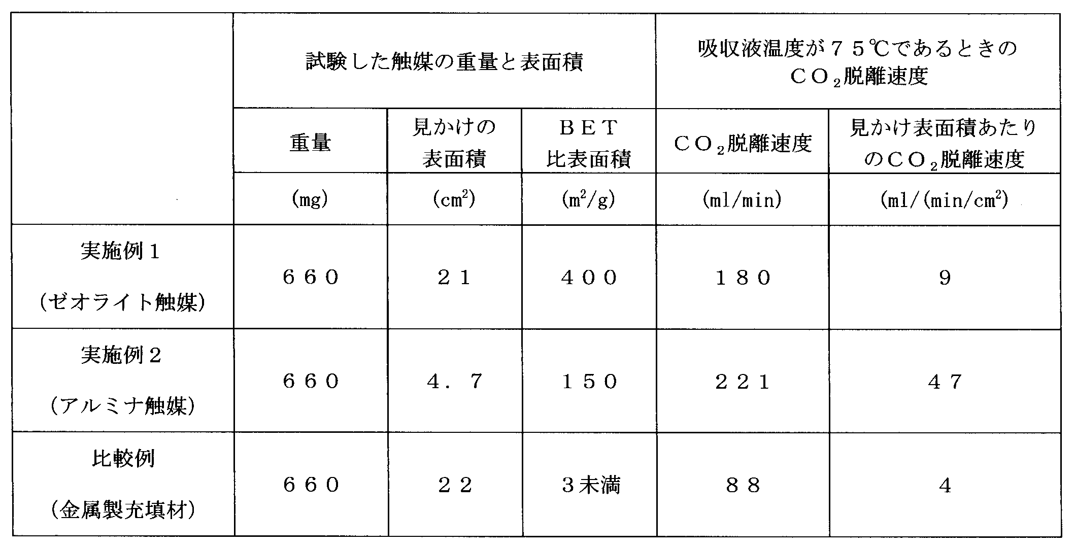
- Test Example 1 Measurement of surface area For each of the catalysts of Examples 1 and 2 and Comparative Example, the apparent surface area was calculated and the BET specific surface area was measured.
- the apparent surface area was calculated from the size and shape of each catalyst.
- the apparent surface area was determined from the diameter, length, and number of stainless yarns constituting the mesh.
- the BET specific surface area was obtained by NOVA-4200e manufactured by QUANTACHROM. The measurement results are shown in Table 1.
- Test Example 2 elimination rate and 151.6 g-CO 2 / L aqueous amine solution 150 that has absorbed CO 2 in the in CO 2 calculation flask desorption rate per apparent surface area of the CO 2 present in the test solution the flask After putting in, each catalyst of Example 1 and 2 or a comparative example was thrown in, and the said absorption liquid was heated until it became 75 degreeC. The heating was performed by heating silicon oil in the oil bath to 90 ° C. and immersing the flask in the silicon oil. Table 1 below shows the test results obtained by measuring the desorbed CO 2 flow rate when the absorption liquid is 75 ° C. with a mass flow flow meter (Azbil Corporation MQV0002).
Landscapes
- Chemical & Material Sciences (AREA)
- Engineering & Computer Science (AREA)
- Chemical Kinetics & Catalysis (AREA)
- Oil, Petroleum & Natural Gas (AREA)
- General Chemical & Material Sciences (AREA)
- Analytical Chemistry (AREA)
- Biomedical Technology (AREA)
- Environmental & Geological Engineering (AREA)
- Health & Medical Sciences (AREA)
- Organic Chemistry (AREA)
- Life Sciences & Earth Sciences (AREA)
- Sustainable Development (AREA)
- Inorganic Chemistry (AREA)
- Treating Waste Gases (AREA)
- Gas Separation By Absorption (AREA)
- Carbon And Carbon Compounds (AREA)
Abstract
Description
また、特許文献1および2に示されるような高温スチームでアミン液が加熱される場合、アミン液から分離した蒸気含有CO2や、CO2分離後のアミン液が高温になる。このため、蒸気含有CO2の冷却による顕熱・潜熱ロスや、アミン液冷却による顕熱ロスが大きい。
(1)塩基性水溶液を冷却する際の排熱量
(2)蒸気含有CO2を冷却する際の排熱量
すなわち、(1)については、上記100℃以下の熱媒体を用いることで、蒸気含有CO2が脱離した後の塩基性水溶液は、高温スチームを利用したときよりも低温になる。従って蒸気含有CO2が脱離した後の塩基性水溶液を吸収塔に導入する前の冷却工程における排熱量を少なくすることができる。
(1)アミン液を冷却する際の排熱量
(2)蒸気含有CO2を冷却する際の排熱量
すなわち、(1)については、上記熱媒体として100℃以下の水を用いることで、蒸気含有CO2が脱離した後のアミン液は、高温スチームを利用したときよりも低温になる。そして、該低温のアミン液が、冷却されて、熱媒体(水)と熱交換される。従ってCO2含有蒸気が脱離した後のアミン液を吸収塔に導入する前の冷却工程における排熱量を少なくすることができる。
本発明の実施例1として、ゼオライト(東ソー株式会社製、商品名HSZ-640 HOD1A,BET比表面積カタログ値400m2/g;直径約1.5mm、長さ約6mmの押出し形状)660mgを用意した。
本発明の実施例2として、球状Al2O3(住友化学株式会社製、商品名KHA-46,BET比表面積カタログ値150m2/g)660mgを用意した。具体的には、直径約5mmである110mgの球状Al2O3を6個用意した。
実施例1,2と比較する比較例として、従来利用されている金属製充填材(660mg)を用意した。具体的には、幅6mm、長さ30mmのステンレスメッシュを直径6mmに丸めることにより得られる金属製充填材(100mg)6個と、幅6mm、長さ18mmのステンレスメッシュ1個を直径6mmに丸めることにより得られる金属製充填材(600mg)1個、の計7個を用意した。
実施例1,2及び比較例の各触媒に対して、見かけの表面積を算出し、BET比表面積を測定した。
フラスコ中に151.6g-CO2/LのCO2を吸収したアミン水溶液150をフラスコ中に入れた後、実施例1及び2又は比較例の各触媒を投入し、上記吸収液を75℃になるまで加熱した。なお、加熱は、オイルバス中のシリコンオイルを90℃に加熱し、当該シリコンオイルにフラスコを浸すことで行った。上記吸収液が75℃であるときの脱離するCO2流量をマスフロー流量計(アズビル株式会社MQV0002)で測定した、試験結果を、下記の表1に示す。
実施例1及び2の触媒を用いた場合のCO2脱離速度は、比較例の金属製充填材を用いた場合のCO2脱離速度よりも高い値を示した。このことから、実施例1及び2で使用した触媒そのものが有するCO2脱離作用は、金属製充填材よりも強いと言える。
2 吸収部
3 再生部
11 吸収液抜出しポンプ
12 加熱容器型再生器再生液抜出しポンプ
21 吸収塔
22 充填材
23 ガス排出口
24 アミン液冷却装置
31 加熱容器型再生器
41 リッチリーン熱交換器
51 冷却装置
52 CO2分離器
H1 塔底部
H2 中間部
H3 塔頂部
L1,L2 CO2吸収後のアミン液ライン
L3,L4 CO2脱離後のアミン液ライン
L5 蒸気含有CO2ライン
101 多管式熱交換器型再生器
102 熱媒体入口
103 熱媒体出口
111 アミン液入口
112 蒸気含有CO2出口
113,114 伝熱管
122 アミン液出口孔
131 邪魔板
201 CO2回収装置2
202 吸収部
203 再生部
211 吸収液抜出しポンプ
212 非加熱容器型再生器再生液抜出しポンプ
221 吸収塔
222 充填材
223 ガス排出口
224 アミン液冷却装置
231 非加熱容器型再生器
232 アミン液加熱用熱交換器
241 リッチリーン熱交換器
251 冷却装置
252 CO2分離器
H201 塔底部
H202 中間部
H203 塔頂部
L201,L202 CO2吸収後のアミン液ライン
L203,L204,L206,L207,L208 CO2脱離後のアミン液ライン
L205 蒸気含有CO2ライン
Claims (18)
- 塩基性水溶液にCO2を吸収させる吸収部と、
CO2が吸収された塩基性水溶液を、100℃以下の熱媒体を用いて加熱し、蒸気含有CO2を脱離させる再生部と
を備えるCO2回収装置。 - 前記CO2が吸収された塩基性水溶液と、蒸気含有CO2が脱離した塩基性水溶液との間で熱交換を行う熱交換器と、
前記蒸気含有CO2が脱離した塩基性水溶液が前記熱交換器を通過した後に、該塩基性水溶液を50℃以下に冷却するクーラーと、
前記蒸気含有CO2を冷却することで、該蒸気含有CO2から水分を除去する冷却装置と
をさらに備える請求項1に記載のCO2回収装置。 - 前記熱媒体は、水である請求項1又は2に記載のCO2回収装置。
- 前記塩基性水溶液は、アルカノールアミン水溶液である請求項1乃至3のいずれかに記載のCO2回収装置。
- 前記アルカノールアミン水溶液が3級アミン液乃至立体障害の大きいアミン液を主成分とする水溶液で、これらのいずれか1種又は2種以上を組み合わせてなる水溶液である請求項4に記載のCO2回収装置。
- 前記再生部では、多管式熱交換器構造の再生器によって、100℃以下の熱媒体を用いて加熱し、蒸気含有CO2を脱離させる請求項1乃至5のいずれかに記載のCO2回収装置。
- 前記再生部は、塩基性水溶液を保有する再生器と、塩基性水溶液を100℃以下の熱媒体で加熱する熱交換器と、前記再生器と前記熱交換器との間で塩基性水溶液を循環させる系統とを有し、
前記系統は、前記再生器においてCO2が脱離して温度が低下した塩基性水溶液を前記熱交換器に供給するとともに、前記熱交換器において100℃以下の熱媒体による加熱で熱が補充された塩基性水溶液を前記再生器に供給する請求項1乃至5のいずれかに記載のCO2回収装置。 - 前記再生器内部の前記塩基性水溶液が存在する部分と、前記再生部における前記塩基性水溶液が通過する流路とのうち、いずれか片方または両方には、無機粉末又は無機粉末の成形体からなる触媒が配置され、
前記無機粉末又は無機粉末の成形体のBET比表面積は、7m2/g以上である、請求項1乃至7のいずれかに記載のCO2回収装置。 - 前記無機粉末又は無機粉末の成形体からなる触媒が、ゼオライト触媒またはアルミナ触媒のいずれか1種又は2種以上の組み合わせである、請求項8に記載のCO2回収装置。
- 塩基性水溶液にCO2を吸収させる吸収工程と、
CO2が吸収された塩基性水溶液を、100℃以下の熱媒体を用いて加熱し、蒸気含有CO2を脱離させる再生工程と
を備えるCO2回収方法。 - 前記CO2が吸収された塩基性水溶液と、蒸気含有CO2が脱離した塩基性水溶液との間で熱交換を行う熱交換工程と、
前記熱交換工程で熱交換が行われた前記蒸気含有CO2が脱離した塩基性水溶液を、50℃以下に冷却する冷却工程と、
前記蒸気含有CO2を冷却することで、該蒸気含有CO2から水分を除去するCO2脱離工程と
をさらに備える請求項10に記載のCO2回収方法。 - 前記熱媒体は、水である請求項10又は11に記載のCO2回収方法。
- 前記塩基性水溶液は、アルカノールアミン水溶液である請求項10乃至12のいずれかに記載のCO2回収方法。
- 前記アルカノールアミン水溶液が3級アミン液乃至立体障害の大きいアミン液を主成分とする水溶液で、これらのいずれか1種又は2種以上を組み合わせてなる水溶液である請求項13に記載のCO2回収方法。
- 前記再生工程では、多管式熱交換器構造の再生器が、前記CO2が吸収された塩基性水溶液を、100℃以下の熱媒体を用いて加熱し、蒸気含有CO2を脱離させる請求項10乃至14のいずれかに記載のCO2回収方法。
- 前記再生工程では、塩基性水溶液を保有する再生器でCO2が脱離するとともに、脱離によって温度が低下した塩基性水溶液を、熱交換器で100℃以下の熱媒体で加熱して、該塩基性水溶液に熱を補充し、該熱を補充した塩基性水溶液を前記再生器に再度供給することにより、蒸気含有CO2を脱離させる請求項10乃至14のいずれかに記載のCO2回収方法。
- 前記再生器内部の前記塩基性水溶液が存在する部分と、前記再生部における前記塩基性水溶液が通過する流路との、いずれか片方または両方には、無機粉末又は無機粉末の成形体からなる触媒が配置され、
前記無機粉末又は無機粉末の成形体のBET比表面積は、7m2/g以上である、請求項10乃至16のいずれかに記載のCO2回収方法。 - 前記無機粉末又は無機粉末の成形体からなる触媒が、ゼオライト触媒またはアルミナ触媒のいずれか1種又は2種以上の組み合わせである、請求項17に記載のCO2回収方法。
Priority Applications (3)
| Application Number | Priority Date | Filing Date | Title |
|---|---|---|---|
| JP2015519708A JP6147339B2 (ja) | 2013-05-28 | 2014-03-19 | Co2回収装置及びco2回収方法 |
| EP14805091.7A EP3012008A4 (en) | 2013-05-28 | 2014-03-19 | Co2 recovery apparatus and co2 recovery method |
| US14/892,619 US10000383B2 (en) | 2013-05-28 | 2014-03-19 | CO2 recovery apparatus and CO2 recovery method |
Applications Claiming Priority (2)
| Application Number | Priority Date | Filing Date | Title |
|---|---|---|---|
| JP2013-111842 | 2013-05-28 | ||
| JP2013111842 | 2013-05-28 |
Publications (1)
| Publication Number | Publication Date |
|---|---|
| WO2014192381A1 true WO2014192381A1 (ja) | 2014-12-04 |
Family
ID=51988425
Family Applications (1)
| Application Number | Title | Priority Date | Filing Date |
|---|---|---|---|
| PCT/JP2014/057557 Ceased WO2014192381A1 (ja) | 2013-05-28 | 2014-03-19 | Co2回収装置及びco2回収方法 |
Country Status (4)
| Country | Link |
|---|---|
| US (1) | US10000383B2 (ja) |
| EP (1) | EP3012008A4 (ja) |
| JP (1) | JP6147339B2 (ja) |
| WO (1) | WO2014192381A1 (ja) |
Cited By (7)
| Publication number | Priority date | Publication date | Assignee | Title |
|---|---|---|---|---|
| JP2018176027A (ja) * | 2017-04-05 | 2018-11-15 | 株式会社東芝 | 二酸化炭素回収システムおよび二酸化炭素回収システムの運転方法 |
| JP2020127934A (ja) * | 2019-02-07 | 2020-08-27 | 株式会社東芝 | 酸性ガス除去装置及び酸性ガス除去方法 |
| JP2021037455A (ja) * | 2019-09-02 | 2021-03-11 | 株式会社東芝 | 二酸化炭素回収システムおよびその運転方法 |
| JP2021137776A (ja) * | 2020-03-09 | 2021-09-16 | 株式会社東芝 | 酸性ガス除去装置および酸性ガス除去方法 |
| JPWO2021193438A1 (ja) * | 2020-03-23 | 2021-09-30 | ||
| JP2023013170A (ja) * | 2021-07-15 | 2023-01-26 | イビデン株式会社 | 二酸化炭素回収装置 |
| CN117815902A (zh) * | 2022-12-22 | 2024-04-05 | 中国石油天然气集团有限公司 | 催化解吸系统 |
Families Citing this family (6)
| Publication number | Priority date | Publication date | Assignee | Title |
|---|---|---|---|---|
| CN109603425A (zh) * | 2018-12-13 | 2019-04-12 | 大连理工大学 | 回收混合气体中二氧化碳的添加碳纳米管的复合脱碳溶液 |
| CN114632402B (zh) * | 2020-12-16 | 2022-11-11 | 中冶京诚工程技术有限公司 | 烟气二氧化碳捕集系统的捕集方法 |
| CN113351148A (zh) * | 2021-06-29 | 2021-09-07 | 西安热工研究院有限公司 | 一种负载复合金属氧化物的催化陶瓷填料及其制备方法 |
| CN114471153A (zh) * | 2022-02-12 | 2022-05-13 | 中太海碳(上海)环保科技有限公司 | 一种用于对溶液中混合有co2的溶液加热和解析的解析塔 |
| CN117582802B (zh) * | 2023-11-29 | 2026-02-06 | 中国石油大学(华东) | 一种超重力装置与能量优化超重力脱碳系统 |
| CN118925447B (zh) * | 2024-08-05 | 2025-12-19 | 深圳市深汕特别合作区华润电力有限公司 | 一种二氧化碳捕集系统及方法 |
Citations (8)
| Publication number | Priority date | Publication date | Assignee | Title |
|---|---|---|---|---|
| JPH05184865A (ja) | 1992-01-17 | 1993-07-27 | Kansai Electric Power Co Inc:The | 燃焼排ガス中の脱二酸化炭素方法 |
| JP2004292298A (ja) * | 2003-02-04 | 2004-10-21 | Nippon Steel Corp | 二酸化炭素の分離回収方法および装置 |
| JP2005211826A (ja) * | 2004-01-30 | 2005-08-11 | Toshiba Corp | 排ガス中の二酸化炭素の回収システムおよび回収方法 |
| JP2011057485A (ja) | 2009-09-08 | 2011-03-24 | Toshiba Corp | 二酸化炭素回収装置 |
| JP2011515211A (ja) * | 2008-03-21 | 2011-05-19 | アルストム テクノロジー リミテッド | 混合ガスストリームからのco2の除去を増進させたシステム及び方法 |
| JP2012143744A (ja) * | 2010-12-22 | 2012-08-02 | Toshiba Corp | 酸性ガス吸収剤、酸性ガス除去方法および酸性ガス除去装置 |
| JP2012533414A (ja) * | 2009-07-23 | 2012-12-27 | キャンソルヴ テクノロジーズ インコーポレーテッド | 二酸化炭素および硫化水素吸収体及びその使用プロセス |
| JP2013512772A (ja) * | 2009-12-09 | 2013-04-18 | ユニバーシティ オブ レジナ | アルコールに基づくガスのストリッピング方法 |
Family Cites Families (13)
| Publication number | Priority date | Publication date | Assignee | Title |
|---|---|---|---|---|
| US5378442A (en) | 1992-01-17 | 1995-01-03 | The Kansai Electric Power Co., Inc. | Method for treating combustion exhaust gas |
| JP3462604B2 (ja) * | 1994-12-26 | 2003-11-05 | 日本パイオニクス株式会社 | 不活性ガスの精製方法および装置 |
| WO2005072851A1 (ja) | 2004-01-30 | 2005-08-11 | Kabushiki Kaisha Toshiba | 排ガス中の二酸化炭素の回収システムおよび回収方法 |
| US7601315B2 (en) * | 2006-12-28 | 2009-10-13 | Cansolv Technologies Inc. | Process for the recovery of carbon dioxide from a gas stream |
| US8414853B2 (en) | 2008-03-21 | 2013-04-09 | Alstom Technology Ltd | System and method for enhanced removal of CO2 from a mixed gas stream via use of a catalyst |
| CA2794751A1 (en) | 2010-03-30 | 2011-10-06 | University Of Regina | Catalytic method and apparatus for separating a gaseous component from an incoming gas stream |
| JP2011240321A (ja) * | 2010-04-20 | 2011-12-01 | Babcock Hitachi Kk | 二酸化炭素除去装置を有する排ガス処理システム |
| AU2011254003B2 (en) | 2010-12-22 | 2013-05-16 | Kabushiki Kaisha Toshiba | Acid gas absorbent, acid gas removal method, and acid gas removal device |
| DE102011013318A1 (de) * | 2011-03-07 | 2012-09-13 | Hochschule Heilbronn | Verfahren zur Regeneration von mit CO2 beladenen aminhaltigen Waschlösungen bei der Sauergaswäsche |
| JP5658101B2 (ja) * | 2011-07-06 | 2015-01-21 | Jfeスチール株式会社 | Co2回収装置及び回収方法 |
| WO2013080889A1 (ja) * | 2011-11-29 | 2013-06-06 | 関西電力株式会社 | Co2脱離触媒 |
| US20160030880A1 (en) * | 2014-07-30 | 2016-02-04 | William Marsh Rice University | Co2 capture with amines and acidic materials |
| CN105749728B (zh) * | 2014-12-16 | 2020-11-17 | 中国科学院上海高等研究院 | 二氧化碳的捕集方法及装置 |
-
2014
- 2014-03-19 JP JP2015519708A patent/JP6147339B2/ja active Active
- 2014-03-19 EP EP14805091.7A patent/EP3012008A4/en not_active Withdrawn
- 2014-03-19 WO PCT/JP2014/057557 patent/WO2014192381A1/ja not_active Ceased
- 2014-03-19 US US14/892,619 patent/US10000383B2/en active Active
Patent Citations (8)
| Publication number | Priority date | Publication date | Assignee | Title |
|---|---|---|---|---|
| JPH05184865A (ja) | 1992-01-17 | 1993-07-27 | Kansai Electric Power Co Inc:The | 燃焼排ガス中の脱二酸化炭素方法 |
| JP2004292298A (ja) * | 2003-02-04 | 2004-10-21 | Nippon Steel Corp | 二酸化炭素の分離回収方法および装置 |
| JP2005211826A (ja) * | 2004-01-30 | 2005-08-11 | Toshiba Corp | 排ガス中の二酸化炭素の回収システムおよび回収方法 |
| JP2011515211A (ja) * | 2008-03-21 | 2011-05-19 | アルストム テクノロジー リミテッド | 混合ガスストリームからのco2の除去を増進させたシステム及び方法 |
| JP2012533414A (ja) * | 2009-07-23 | 2012-12-27 | キャンソルヴ テクノロジーズ インコーポレーテッド | 二酸化炭素および硫化水素吸収体及びその使用プロセス |
| JP2011057485A (ja) | 2009-09-08 | 2011-03-24 | Toshiba Corp | 二酸化炭素回収装置 |
| JP2013512772A (ja) * | 2009-12-09 | 2013-04-18 | ユニバーシティ オブ レジナ | アルコールに基づくガスのストリッピング方法 |
| JP2012143744A (ja) * | 2010-12-22 | 2012-08-02 | Toshiba Corp | 酸性ガス吸収剤、酸性ガス除去方法および酸性ガス除去装置 |
Non-Patent Citations (1)
| Title |
|---|
| See also references of EP3012008A4 * |
Cited By (13)
| Publication number | Priority date | Publication date | Assignee | Title |
|---|---|---|---|---|
| JP2018176027A (ja) * | 2017-04-05 | 2018-11-15 | 株式会社東芝 | 二酸化炭素回収システムおよび二酸化炭素回収システムの運転方法 |
| JP7102376B2 (ja) | 2019-02-07 | 2022-07-19 | 株式会社東芝 | 酸性ガス除去装置及び酸性ガス除去方法 |
| JP2020127934A (ja) * | 2019-02-07 | 2020-08-27 | 株式会社東芝 | 酸性ガス除去装置及び酸性ガス除去方法 |
| JP2021037455A (ja) * | 2019-09-02 | 2021-03-11 | 株式会社東芝 | 二酸化炭素回収システムおよびその運転方法 |
| JP7278908B2 (ja) | 2019-09-02 | 2023-05-22 | 株式会社東芝 | 二酸化炭素回収システムおよびその運転方法 |
| JP2021137776A (ja) * | 2020-03-09 | 2021-09-16 | 株式会社東芝 | 酸性ガス除去装置および酸性ガス除去方法 |
| JP7360344B2 (ja) | 2020-03-09 | 2023-10-12 | 株式会社東芝 | 酸性ガス除去装置および酸性ガス除去方法 |
| WO2021193438A1 (ja) * | 2020-03-23 | 2021-09-30 | 株式会社Ihi | 炭化水素生成システム、及び炭化水素生成方法 |
| JPWO2021193438A1 (ja) * | 2020-03-23 | 2021-09-30 | ||
| US11795121B2 (en) | 2020-03-23 | 2023-10-24 | Ihi Corporation | Hydrocarbon generation system and hydrocarbon generation method |
| JP7747620B2 (ja) | 2020-03-23 | 2025-10-01 | 株式会社Ihi | 炭化水素生成システム、及び炭化水素生成方法 |
| JP2023013170A (ja) * | 2021-07-15 | 2023-01-26 | イビデン株式会社 | 二酸化炭素回収装置 |
| CN117815902A (zh) * | 2022-12-22 | 2024-04-05 | 中国石油天然气集团有限公司 | 催化解吸系统 |
Also Published As
| Publication number | Publication date |
|---|---|
| US10000383B2 (en) | 2018-06-19 |
| US20160115034A1 (en) | 2016-04-28 |
| EP3012008A1 (en) | 2016-04-27 |
| EP3012008A4 (en) | 2017-01-25 |
| JPWO2014192381A1 (ja) | 2017-02-23 |
| JP6147339B2 (ja) | 2017-06-14 |
Similar Documents
| Publication | Publication Date | Title |
|---|---|---|
| JP6147339B2 (ja) | Co2回収装置及びco2回収方法 | |
| JP5759566B2 (ja) | Co2脱離触媒 | |
| TWI491726B (zh) | 氣體精製方法、煤氣化設備及轉移觸媒 | |
| JP5658243B2 (ja) | Co2吸収剤の再生利用のための方法および再生利用器 | |
| JP2014520661A (ja) | アミン吸収剤およびco2捕獲方法 | |
| JP2008296216A (ja) | アンモニア水を利用する二酸化炭素回収装置及びその方法 | |
| JP2022066275A (ja) | 工業的プロセスからのco2排出を減少する方法とシステム | |
| KR101709867B1 (ko) | 이산화탄소 포집장치 | |
| JP2013059726A (ja) | Co2回収装置およびco2回収方法 | |
| JP2013059727A (ja) | Co2回収装置およびco2回収方法 | |
| CN101856589A (zh) | 一种富含一氧化碳的工业尾气的净化方法 | |
| WO2018190104A1 (ja) | 燃焼排ガス中の二酸化炭素を回収するための装置及び方法 | |
| JP6307279B2 (ja) | 二酸化炭素ガス回収装置及び回収方法 | |
| JP2018001086A (ja) | 二酸化炭素回収システムおよび排ガス処理方法 | |
| WO2017130863A1 (ja) | Co2回収装置及びco2回収方法 | |
| JP2011177685A (ja) | 浄化装置及び二酸化炭素回収システム | |
| JP6576288B2 (ja) | 二酸化炭素ガスの回収装置、及び、二酸化炭素ガスの製造方法 | |
| CN104936678B (zh) | 含co2及h2s的气体的回收系统及回收方法 | |
| JP6918718B2 (ja) | 酸性ガス回収装置および酸性ガス回収方法 | |
| CN113694698A (zh) | 一种用于bdo生产的乙炔尾气回收装置 | |
| JP6830413B2 (ja) | 二酸化炭素の回収設備、及び、二酸化炭素の回収方法 | |
| JP2016112482A (ja) | 二酸化炭素回収方法および二酸化炭素回収装置 | |
| WO2020174858A1 (ja) | 二酸化炭素の製造方法、及び二酸化炭素の製造装置 | |
| JP4724418B2 (ja) | メタノールから二酸化炭素を除去するためのシステムユニット | |
| JP2016112497A (ja) | 二酸化炭素の回収装置および回収方法 |
Legal Events
| Date | Code | Title | Description |
|---|---|---|---|
| 121 | Ep: the epo has been informed by wipo that ep was designated in this application |
Ref document number: 14805091 Country of ref document: EP Kind code of ref document: A1 |
|
| ENP | Entry into the national phase |
Ref document number: 2015519708 Country of ref document: JP Kind code of ref document: A |
|
| WWE | Wipo information: entry into national phase |
Ref document number: 14892619 Country of ref document: US |
|
| NENP | Non-entry into the national phase |
Ref country code: DE |
|
| WWE | Wipo information: entry into national phase |
Ref document number: 2014805091 Country of ref document: EP |
|
| WWW | Wipo information: withdrawn in national office |
Ref document number: 2014805091 Country of ref document: EP |