WO2014192461A1 - Soufflante - Google Patents
Soufflante Download PDFInfo
- Publication number
- WO2014192461A1 WO2014192461A1 PCT/JP2014/061265 JP2014061265W WO2014192461A1 WO 2014192461 A1 WO2014192461 A1 WO 2014192461A1 JP 2014061265 W JP2014061265 W JP 2014061265W WO 2014192461 A1 WO2014192461 A1 WO 2014192461A1
- Authority
- WO
- WIPO (PCT)
- Prior art keywords
- blower
- fan
- blade
- sirocco fan
- air
- Prior art date
- Legal status (The legal status is an assumption and is not a legal conclusion. Google has not performed a legal analysis and makes no representation as to the accuracy of the status listed.)
- Ceased
Links
Images





Classifications
-
- F—MECHANICAL ENGINEERING; LIGHTING; HEATING; WEAPONS; BLASTING
- F04—POSITIVE - DISPLACEMENT MACHINES FOR LIQUIDS; PUMPS FOR LIQUIDS OR ELASTIC FLUIDS
- F04D—NON-POSITIVE-DISPLACEMENT PUMPS
- F04D17/00—Radial-flow pumps, e.g. centrifugal pumps; Helico-centrifugal pumps
- F04D17/08—Centrifugal pumps
- F04D17/10—Centrifugal pumps for compressing or evacuating
- F04D17/12—Multi-stage pumps
- F04D17/127—Multi-stage pumps with radially spaced stages, e.g. for contrarotating type
-
- F—MECHANICAL ENGINEERING; LIGHTING; HEATING; WEAPONS; BLASTING
- F04—POSITIVE - DISPLACEMENT MACHINES FOR LIQUIDS; PUMPS FOR LIQUIDS OR ELASTIC FLUIDS
- F04D—NON-POSITIVE-DISPLACEMENT PUMPS
- F04D17/00—Radial-flow pumps, e.g. centrifugal pumps; Helico-centrifugal pumps
- F04D17/08—Centrifugal pumps
- F04D17/16—Centrifugal pumps for displacing without appreciable compression
-
- F—MECHANICAL ENGINEERING; LIGHTING; HEATING; WEAPONS; BLASTING
- F04—POSITIVE - DISPLACEMENT MACHINES FOR LIQUIDS; PUMPS FOR LIQUIDS OR ELASTIC FLUIDS
- F04D—NON-POSITIVE-DISPLACEMENT PUMPS
- F04D17/00—Radial-flow pumps, e.g. centrifugal pumps; Helico-centrifugal pumps
- F04D17/08—Centrifugal pumps
- F04D17/16—Centrifugal pumps for displacing without appreciable compression
- F04D17/164—Multi-stage fans, e.g. for vacuum cleaners
Definitions
- the present invention relates to a blower.
- a blower using a sirocco fan is disclosed in JP2012-207661A.
- the blower using the sirocco fan since the blower using the sirocco fan has no blades on the radially inner side, the air near the rotating shaft is difficult to flow outward in the radial direction, and if the air near the rotating shaft can be blown out radially outwards, The blower blowing performance can be improved.
- the present invention was invented to solve such problems, and aims to improve the blower blowing performance by blowing out air in the vicinity of the rotating shaft radially outward.
- a blower according to an aspect of the present invention includes a sirocco fan and a turbo fan or a mixed flow fan provided radially inward of the blades of the sirocco fan.
- the air in the vicinity of the rotating shaft can be blown out radially outward by the turbo fan or the mixed flow fan, and the blower performance of the blower can be improved.
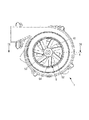
- FIG. 1 is a perspective view of the blower of the first embodiment.
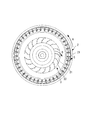
- FIG. 2 is a plan view of the blower of the first embodiment.
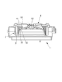
- 3 is a cross-sectional view taken along the line III-III in FIG.
- FIG. 4 is a diagram for explaining the flow of air in the blower.
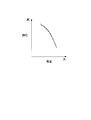
- FIG. 5 is a diagram showing air volume-static pressure characteristics in the blower of the first embodiment and the comparative example.
- FIG. 6 is a perspective view showing a modification of the first embodiment.
- FIG. 7 is a perspective view of the blower of the second embodiment.
- FIG. 8 is a plan view of the blower of the second embodiment.
- 9 is a cross-sectional view taken along the line IX-IX in FIG.
- FIG. 10 is a plan view of the mixed flow fan.
- FIG. 1 is a perspective view of the blower 1.
- FIG. 2 is a plan view of the blower 1.
- 3 is a cross-sectional view taken along the line III-III in FIG.
- the blower 1 includes a sirocco fan 2, a turbo fan 3, and a blower case 4.
- the blower 1 allows air to flow in from an inflow port 41 that opens in the axial direction via a duct (not shown), and blows out the air radially outward by the turbo fan 3 and the sirocco fan 2. Exhaust air out of the air.
- the sirocco fan 2 includes a plurality of first blades 21 arranged at equal intervals along the circumferential direction, and a first connecting portion 22 that connects the first blades 21 and a rotation shaft (not shown).
- the sirocco fan 2 rotates together with the rotating shaft when the rotating shaft rotates by an electric motor (not shown) or the like.
- the first connecting portion 22 is formed with a first insertion hole 23 into which the rotating shaft is inserted and engaged with the rotating shaft.
- the first connecting portion 22 protrudes from the bottom side of the blower 1 to the duct side, and connects the first blade 21 on the bottom side of the blower 1 and the rotating shaft.
- a part of the electric motor is accommodated in the space formed by the first connecting portion 22 projecting toward the duct side.
- the turbofan 3 includes a plurality of second blades 31 arranged at equal intervals along the circumferential direction, a second connecting portion 32 that connects the second blades 31 and the rotating shaft, and a second blade 31 on the duct side.
- a cover 33 is provided.
- the turbo fan 3 is provided radially inward of the first blade 21 of the sirocco fan 2 so that a gap is generated between the outer peripheral end of the second blade 31 and the inner peripheral end of the first blade 21 of the sirocco fan 2. Is provided.
- the turbo fan 3 is provided coaxially with the sirocco fan 2 and rotates together with the sirocco fan 2 when the rotation shaft rotates.
- the second connecting portion 32 is formed with a rotation shaft and a second insertion hole 34 into which a part of the first connecting portion 22 is inserted.
- the second connecting part 32 is placed on the first connecting part 22 and connects the second blade 31 on the bottom side of the blower 1 and the rotary shaft via the first connecting part 22.
- the second connecting portion 32 and the rotating shaft are connected via the first connecting portion 22, but the rotating shaft and the second connecting portion 32 may be directly connected.
- the cover 33 is connected to the second blade 31 on the duct side and is formed to cover the second blade 31 on the duct side.
- the cover 33 extends from the radially inner side toward the first blade 21 of the sirocco fan 2 and is formed so that the air blown out by the turbo fan 3 does not escape to the duct side.
- a hole 35 is formed on the radially inner side to take in the air on the radially inner side (near the rotation shaft) into the turbofan 3.
- the blower case 4 is formed with an inflow port 41 through which air flows in through a duct, a flow path 42 through which air blown by the sirocco fan 2 flows, and an exhaust port 43 through which air is discharged from the blower 1.
- FIG. 4 is a plan view showing only the turbo fan 3 and the sirocco fan 2.
- the turbo fan 3 blows out the air in the radial direction (near the rotation axis) in the direction opposite to the rotation direction of the sirocco fan 2 as indicated by an arrow B in FIG.
- the turbo fan 3 includes a cover 33 that covers the second blade 31 on the duct side and extends toward the first blade 21, and air blown radially outward by the turbo fan 3 is directed to the duct side. It flows toward Sirocco fan 2 without running away.
- the air blown out from the turbo fan 3 is blown out radially outward by the sirocco fan 2 as shown by an arrow C in FIG.
- the relative velocity of the air on the inner peripheral side of the first blade 21 of the sirocco fan 2 is increased.
- a gap is provided between the second blade 31 of the turbo fan 3 and the first blade 21 of the sirocco fan 2, and the sirocco fan 2 further takes in air from this gap and blows the air radially outward. .
- the air blown out to the flow path 42 by the sirocco fan 2 is discharged out of the blower 1 through the discharge port 43.
- FIG. 5 shows the static pressure-air flow characteristics between the blower 1 of the first embodiment and the blower of the comparative example in which only the sirocco fan 2 is provided without the turbo fan 3.
- the static pressure-air volume characteristic of the blower 1 of the present embodiment is indicated by a solid line
- the static pressure-air volume characteristic of the blower of the comparative example is indicated by a broken line. According to this, the blower 1 of this embodiment can raise the static pressure at the time of low air volume with respect to the blower of a comparative example, and was able to improve the ventilation performance of the blower 1.
- the turbo fan 3 that blows air in the direction opposite to the rotation direction of the sirocco fan 2 on the radially inner side, the air near the rotation shaft can be blown out radially by the turbo fan 3.
- the relative velocity of air on the inner peripheral end side of one blade 21 is increased. Thereby, the static pressure at the time of a low air volume can be made high, and the ventilation performance of the blower 1 can be improved.
- the blower 1 provides a gap between the outer peripheral end of the second blade 31 of the turbo fan 3 and the inner peripheral end of the first blade 21 of the sirocco fan 2. Air can be newly taken in, the diameter of the inner periphery of the first blade 21 of the sirocco fan 2 can be prevented from being reduced, and the blowing performance of the blower 1 can be prevented from being lowered.
- the electric motor for rotating the sirocco fan 2 and the like can be disposed radially inward of the first connecting portion 22 and is axially The length of the blower 1 can be reduced.
- FIG. 6 is a perspective view of a modified blower 1.
- a part of the turbo fan 3 protrudes to the duct side from the inlet 41 of the blower case 4.
- the air outside the blower case 4 can be further taken in by the turbo fan 3 and the blower performance of the blower 1 can be improved.
- FIG. 7 is a perspective view of the blower 1.
- FIG. 8 is a plan view of the blower 1.
- 9 is a cross-sectional view taken along the line IX-IX in FIG.
- the blower 1 includes a sirocco fan 2, a mixed flow fan 5, and a blower case 4.
- the mixed flow fan 5 includes a plurality of third blades 51 arranged at equal intervals along the circumferential direction, and a third connecting portion 52 that connects the third blade 51 and the rotation shaft.
- the mixed flow fan 5 is provided radially inward of the first blade 21 of the sirocco fan 2, and a gap is generated between the outer peripheral end of the third blade 51 and the inner peripheral end of the first blade 21 of the sirocco fan 2. It is provided as follows.
- the mixed flow fan 5 is provided coaxially with the sirocco fan 2 and rotates together with the sirocco fan 2 when the rotation shaft rotates.
- the third blade 51 extends obliquely upward from the third connecting portion 52, and extends so that the tip side is positioned forward in the rotation direction with respect to the connecting portion with the third connecting portion 52. . That is, the 3rd blade
- wing 51 is formed so that an outer peripheral side may be located back in a rotation direction rather than an inner peripheral side. That is, as shown in FIG. 10, the third blade 51 is formed such that the outer peripheral side is located on the rear side in the rotational direction with respect to the line passing through the rotation shaft and the inner peripheral end 54 of the third blade 51.
- the third connecting part 52 is formed with a rotating shaft and a third insertion hole 53 into which a part of the first connecting part 22 is inserted.
- the third connecting part 52 is placed on the first connecting part 22 and connects the third blade 51 and the rotating shaft via the first connecting part 22.
- the air flowing into the blower 1 from the inlet 41 is compressed by the mixed flow fan 5 as it approaches the third connecting portion 52, ie, radially outside the mixed flow fan 5, that is, the sirocco fan 2. It flows toward. Further, the mixed flow fan 5 blows out air in the direction opposite to the rotation direction of the sirocco fan 2 as in the turbo fan 3 of the first embodiment.
- the area of the second blade 31 of the turbo fan 3 or the second blade 31 of the turbo fan 3 and the sirocco fan when the diameter of the blower 1 is reduced. It may be difficult to secure a gap between the first blade 21 and the second blade 21.
- the blower 1 even when the blower 1 is downsized by using the mixed flow fan 5, it is possible to suppress a decrease in the blowing performance of the blower 1 by changing the shape of the third blade 51 or the like. Therefore, the blower 1 can be reduced in size and the design freedom of the blower 1 can be improved.
- a part of the mixed flow fan 5 may protrude from the inlet 41 of the blower case 4 to the duct side.
- turbo fan 3 and the sirocco fan 2 are configured by different members, but at least a part of the turbo fan 3 and the sirocco fan 2 may be integrally configured by the same member.
Landscapes
- Engineering & Computer Science (AREA)
- Mechanical Engineering (AREA)
- General Engineering & Computer Science (AREA)
- Structures Of Non-Positive Displacement Pumps (AREA)
Abstract
Cette invention concerne une soufflante, comprenant un ventilateur de type sirocco, et un ventilateur à double flux ou un ventilateur à flux mixte disposé radialement à l'intérieur des aubes du ventilateur de type sirocco.
Applications Claiming Priority (4)
| Application Number | Priority Date | Filing Date | Title |
|---|---|---|---|
| JP2013-113101 | 2013-05-29 | ||
| JP2013113101 | 2013-05-29 | ||
| JP2014004782A JP2015007419A (ja) | 2013-05-29 | 2014-01-15 | ブロワ |
| JP2014-004782 | 2014-01-15 |
Publications (1)
| Publication Number | Publication Date |
|---|---|
| WO2014192461A1 true WO2014192461A1 (fr) | 2014-12-04 |
Family
ID=51988500
Family Applications (1)
| Application Number | Title | Priority Date | Filing Date |
|---|---|---|---|
| PCT/JP2014/061265 Ceased WO2014192461A1 (fr) | 2013-05-29 | 2014-04-22 | Soufflante |
Country Status (2)
| Country | Link |
|---|---|
| JP (1) | JP2015007419A (fr) |
| WO (1) | WO2014192461A1 (fr) |
Citations (5)
| Publication number | Priority date | Publication date | Assignee | Title |
|---|---|---|---|---|
| JPS61118998U (fr) * | 1985-01-09 | 1986-07-26 | ||
| JPH01102499U (fr) * | 1987-12-25 | 1989-07-11 | ||
| JPH0419695U (fr) * | 1990-06-05 | 1992-02-19 | ||
| JPH11280695A (ja) * | 1998-03-26 | 1999-10-15 | Kubota Corp | 施肥装置用の遠心ブロワ |
| JP2007120378A (ja) * | 2005-10-27 | 2007-05-17 | Nippon Densan Corp | 遠心ファン |
-
2014
- 2014-01-15 JP JP2014004782A patent/JP2015007419A/ja active Pending
- 2014-04-22 WO PCT/JP2014/061265 patent/WO2014192461A1/fr not_active Ceased
Patent Citations (5)
| Publication number | Priority date | Publication date | Assignee | Title |
|---|---|---|---|---|
| JPS61118998U (fr) * | 1985-01-09 | 1986-07-26 | ||
| JPH01102499U (fr) * | 1987-12-25 | 1989-07-11 | ||
| JPH0419695U (fr) * | 1990-06-05 | 1992-02-19 | ||
| JPH11280695A (ja) * | 1998-03-26 | 1999-10-15 | Kubota Corp | 施肥装置用の遠心ブロワ |
| JP2007120378A (ja) * | 2005-10-27 | 2007-05-17 | Nippon Densan Corp | 遠心ファン |
Also Published As
| Publication number | Publication date |
|---|---|
| JP2015007419A (ja) | 2015-01-15 |
Similar Documents
| Publication | Publication Date | Title |
|---|---|---|
| US10064470B2 (en) | Motor and a hair care appliance comprising a motor | |
| ES2901052T3 (es) | Entrada para ventilador axial | |
| WO2016068280A1 (fr) | Dispositif de ventilation, et aspirateur | |
| EP3597929A1 (fr) | Ventilateur de refroidissement et dispositif de refroidissement de siège le comprenant | |
| JP2014058966A (ja) | 熱交換器のためのファンモジュール | |
| CN106062380B (zh) | 送风装置 | |
| JP2015108369A5 (fr) | ||
| JP4389998B2 (ja) | 遠心式多翼ファン | |
| JP4292417B2 (ja) | 遠心ファンのインペラ | |
| JP6332546B2 (ja) | 遠心送風機 | |
| JP6504754B2 (ja) | 電動送風機およびそれを用いた電気掃除機 | |
| JP6798011B2 (ja) | 電動送風機、電気掃除機、及び手乾燥装置 | |
| JP6681539B2 (ja) | 送風装置 | |
| ITBO20110543A1 (it) | Ventilatore centrifugo. | |
| JP2016116272A (ja) | 回転電機及びファンカバー | |
| JP2016102467A (ja) | 送風装置 | |
| KR20170050309A (ko) | 공기청정기의 축류형 송풍팬 | |
| CN204783822U (zh) | 离心鼓风机 | |
| US10495114B2 (en) | Blower | |
| JP6719670B2 (ja) | 電動送風機、電気掃除機、及び手乾燥装置 | |
| JP2017125405A5 (fr) | ||
| JP2005171987A (ja) | 小型斜流ファンモータ | |
| WO2014192461A1 (fr) | Soufflante | |
| WO2015122134A1 (fr) | Soufflante | |
| JP5022185B2 (ja) | 遠心式多翼送風機 |
Legal Events
| Date | Code | Title | Description |
|---|---|---|---|
| 121 | Ep: the epo has been informed by wipo that ep was designated in this application |
Ref document number: 14804793 Country of ref document: EP Kind code of ref document: A1 |
|
| NENP | Non-entry into the national phase |
Ref country code: DE |
|
| 122 | Ep: pct application non-entry in european phase |
Ref document number: 14804793 Country of ref document: EP Kind code of ref document: A1 |