WO2014192529A1 - Dispositif, procédé et programme d'estimation de points de changement de direction de courant, dispositif d'estimation de ride de courant et dispositif radar - Google Patents
Dispositif, procédé et programme d'estimation de points de changement de direction de courant, dispositif d'estimation de ride de courant et dispositif radar Download PDFInfo
- Publication number
- WO2014192529A1 WO2014192529A1 PCT/JP2014/062657 JP2014062657W WO2014192529A1 WO 2014192529 A1 WO2014192529 A1 WO 2014192529A1 JP 2014062657 W JP2014062657 W JP 2014062657W WO 2014192529 A1 WO2014192529 A1 WO 2014192529A1
- Authority
- WO
- WIPO (PCT)
- Prior art keywords
- direction change
- flow direction
- wavefront
- tide
- change point
- Prior art date
- Legal status (The legal status is an assumption and is not a legal conclusion. Google has not performed a legal analysis and makes no representation as to the accuracy of the status listed.)
- Ceased
Links
Images




Classifications
-
- G—PHYSICS
- G01—MEASURING; TESTING
- G01S—RADIO DIRECTION-FINDING; RADIO NAVIGATION; DETERMINING DISTANCE OR VELOCITY BY USE OF RADIO WAVES; LOCATING OR PRESENCE-DETECTING BY USE OF THE REFLECTION OR RERADIATION OF RADIO WAVES; ANALOGOUS ARRANGEMENTS USING OTHER WAVES
- G01S13/00—Systems using the reflection or reradiation of radio waves, e.g. radar systems; Analogous systems using reflection or reradiation of waves whose nature or wavelength is irrelevant or unspecified
- G01S13/88—Radar or analogous systems specially adapted for specific applications
- G01S13/95—Radar or analogous systems specially adapted for specific applications for meteorological use
- G01S13/956—Radar or analogous systems specially adapted for specific applications for meteorological use mounted on ship or other platform
-
- G—PHYSICS
- G01—MEASURING; TESTING
- G01S—RADIO DIRECTION-FINDING; RADIO NAVIGATION; DETERMINING DISTANCE OR VELOCITY BY USE OF RADIO WAVES; LOCATING OR PRESENCE-DETECTING BY USE OF THE REFLECTION OR RERADIATION OF RADIO WAVES; ANALOGOUS ARRANGEMENTS USING OTHER WAVES
- G01S13/00—Systems using the reflection or reradiation of radio waves, e.g. radar systems; Analogous systems using reflection or reradiation of waves whose nature or wavelength is irrelevant or unspecified
- G01S13/02—Systems using reflection of radio waves, e.g. primary radar systems; Analogous systems
- G01S13/50—Systems of measurement based on relative movement of target
- G01S13/58—Velocity or trajectory determination systems; Sense-of-movement determination systems
- G01S13/589—Velocity or trajectory determination systems; Sense-of-movement determination systems measuring the velocity vector
-
- G—PHYSICS
- G01—MEASURING; TESTING
- G01P—MEASURING LINEAR OR ANGULAR SPEED, ACCELERATION, DECELERATION, OR SHOCK; INDICATING PRESENCE, ABSENCE, OR DIRECTION, OF MOVEMENT
- G01P5/00—Measuring speed of fluids, e.g. of air stream; Measuring speed of bodies relative to fluids, e.g. of ship, of aircraft
- G01P5/001—Full-field flow measurement, e.g. determining flow velocity and direction in a whole region at the same time, flow visualisation
-
- Y—GENERAL TAGGING OF NEW TECHNOLOGICAL DEVELOPMENTS; GENERAL TAGGING OF CROSS-SECTIONAL TECHNOLOGIES SPANNING OVER SEVERAL SECTIONS OF THE IPC; TECHNICAL SUBJECTS COVERED BY FORMER USPC CROSS-REFERENCE ART COLLECTIONS [XRACs] AND DIGESTS
- Y02—TECHNOLOGIES OR APPLICATIONS FOR MITIGATION OR ADAPTATION AGAINST CLIMATE CHANGE
- Y02A—TECHNOLOGIES FOR ADAPTATION TO CLIMATE CHANGE
- Y02A90/00—Technologies having an indirect contribution to adaptation to climate change
- Y02A90/10—Information and communication technologies [ICT] supporting adaptation to climate change, e.g. for weather forecasting or climate simulation
Definitions
- the present invention relates to a flow direction change point estimation device for estimating a flow direction change point at which the flow direction of a wave front greatly changes, a tide estimator for estimating a tide, a radar device including the tide estimator, and a tide estimate.
- the present invention relates to a tide estimation method and a tide estimation program.
- a tide detector (tide estimator) that can confirm the position of a tide generated in the sea is known.
- the flow velocity of tidal currents in a plurality of layers in the depth direction is obtained based on the frequency of reflected echoes that are returned by transmitting ultrasonic waves below the ship.
- the tide is estimated by calculating
- the present invention is for solving the above-mentioned problems, and its purpose is to estimate the distribution state of flow direction change points in a short time.
- a flow direction change point estimation device includes a derivation unit that derives a wavefront velocity vector that is a velocity vector of a wavefront wave surface at each point in a predetermined range; The angle difference between adjacent wavefront velocity vectors among the wavefront velocity vectors derived at each point derived by the deriving unit is compared. If the angle difference is equal to or greater than a predetermined value, the position between the adjacent wavefront velocity vectors is changed in the flow direction. And a flow direction change point estimation unit that estimates a plurality of flow direction change points.
- a tide estimation device includes a plurality of the flow direction change point estimation devices estimated by the flow direction change point estimation device and the flow direction change point estimation unit of the flow direction change point estimation device.
- a tide estimator that estimates tide based on the flow direction change point.
- the tide estimator calculates an approximate function of the plurality of flow direction change points estimated by the flow direction change point estimator, and estimates the tide based on the approximate function.
- a radar apparatus is based on an antenna that transmits and receives radio waves and a wave front of a water surface at each point in a predetermined range based on a reception signal received by the antenna.
- the flow direction change point estimation device having a derivation unit for deriving a wavefront velocity vector that is a velocity vector, and a display that displays the plurality of flow direction change points estimated by the flow direction change point estimation device so that a user can recognize them And a section.
- a radar apparatus is based on an antenna that transmits and receives radio waves and a wave front of a water surface at each point in a predetermined range based on a reception signal received by the antenna.
- the tide estimation device having a derivation unit for deriving a wavefront velocity vector that is a velocity vector, and a display unit that displays the tide estimated by the tide estimation device so that the user can recognize the tide.
- a flow direction change point estimation method includes a step of deriving a wavefront velocity vector that is a velocity vector of a wavefront wave surface at each point in a predetermined range; A step of comparing an angular difference between adjacent wavefront velocity vectors among the wavefront velocity vectors at each point derived in the step of deriving a velocity vector, and when the angle difference is equal to or greater than a predetermined value, Estimating a position between them as a flow direction change point, and estimating a plurality of the flow direction change points.
- a flow direction change point estimation program includes a step of deriving a wavefront velocity vector that is a velocity vector of a wavefront wavefront at each point in a predetermined range; A step of comparing an angular difference between adjacent wavefront velocity vectors among the wavefront velocity vectors at each point derived in the step of deriving a velocity vector, and when the angle difference is equal to or greater than a predetermined value, Estimating a position between them as a flow direction change point, and estimating a plurality of the flow direction change points.
- the distribution state of flow direction change points can be estimated in a short time.
- FIG. 1 It is a block diagram which shows the structure of the radar apparatus which concerns on embodiment of this invention. It is a figure which shows the example of a display when the distribution state of the wave front velocity vector calculated by the tide estimation apparatus shown in FIG. 1 is displayed on a 2nd display. It is a figure which shows the example of a display of the calculation result of the tide eye estimation apparatus shown in FIG. It is a flowchart for demonstrating operation
- FIG. It is a figure which shows the example of a display of the calculation result of the tide eye estimation apparatus shown in FIG. It is a block diagram which shows the structure of the radar apparatus which concerns on a modification. It is a figure which shows the example of a display of the calculation result of the flow direction change point estimation apparatus shown in FIG. It is a figure for demonstrating the estimation method of the flow direction change point in the radar apparatus which concerns on a modification. It is a block diagram which shows the structure of the radar apparatus which concerns on a modification. It is a block diagram which shows the structure of the radar apparatus which concerns on a modification. It is a block diagram which shows the structure of the radar apparatus which concerns on a modification.
- the tide estimation device 10 and the radar device 1 including the tide estimation device 10 according to an embodiment of the present invention will be described with reference to the drawings.
- the radar apparatus 1 according to the embodiment of the present invention is installed in, for example, a ship (own ship) and is used to detect a target on the sea (for example, another ship).
- the radar apparatus 1 according to the present embodiment is configured so that the tide level can be estimated by the tide level estimation apparatus 10.
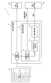
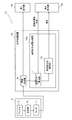
- FIG. 1 is a block diagram showing a configuration of a radar apparatus 1 according to an embodiment of the present invention.
- the radar device 1 includes an antenna unit 2, a signal processing device 3, a first display 4a, and a second display 4b (display unit).
- the antenna unit 2 includes an antenna 5, a receiving unit 6, and an A / D conversion unit 7.
- the antenna 5 is a radar antenna capable of transmitting (radiating) a pulsed radio wave having strong directivity.
- the antenna 5 is configured to receive an echo signal (reflected wave) from a target. That is, the antenna 5 is configured to receive an echo signal that identifies a target.
- the radar apparatus 1 measures the time from when a pulsed radio wave is transmitted to when an echo signal is received. Thereby, the radar apparatus 1 can detect the distance r to the target.
- the direction in which the ship and the target face each other is defined as the distance direction.
- the antenna 5 is configured to be able to rotate 360 ° on a horizontal plane, and rotates around the vertical axis.
- the antenna 5 is configured to repeatedly transmit and receive radio waves while changing the transmission direction of pulsed radio waves (changing the rotation angle of the antenna 5). With the above configuration, the radar apparatus 1 can detect a target on a plane around the ship over 360 °.
- the receiving unit 6 detects and amplifies the echo signal received by the antenna 5.
- the echo signal is a reflected wave at a target or wave front with respect to a transmission signal from the antenna 5 among signals received by the antenna 5.
- the reception unit 6 outputs the amplified echo signal to the A / D conversion unit 7.
- the A / D converter 7 samples an analog echo signal and converts it into digital data (echo data) consisting of a plurality of bits.
- the value of the echo data includes data for specifying the intensity (signal level) of the echo signal received by the antenna 5.
- the A / D converter 7 outputs the echo data to the image generator 8 of the signal processing device 3.
- the signal processing device 3 includes an image generation unit 8 and a tide estimation device 10.
- the image generation unit 8 generates image data based on data having a relatively high signal level (for example, other ships) based on the echo data from the A / D conversion unit 7.
- the image generation unit 8 generates PPI (Plan Position Indicator) image data.
- the image data generated by the image generation unit 8 is output to the first display 4a. Thereby, the user can grasp
- the image generation unit 8 generates image data based on the reflected wave from the sea surface based on the echo data from the A / D conversion unit 7.
- the image generation unit 8 generates the image data at a plurality of timings.
- the image data generated in this way is output to the tide estimation device 10.
- the tide estimation device 10 is configured to estimate the distribution of the wave front velocity vector and the tide based on the image data based on the reflected wave from the sea surface. The configuration of the tide estimation device 10 will be described later in detail.
- the first display 4a displays the image signal generated by the image generation unit 8 (image signal caused by another ship or the like). Further, the second display 4b displays the wavefront velocity vector distribution calculated by the tide estimator 10 and the tide. For example, the second display 4b is configured to display the wavefront velocity vector distribution and the tide by switching a changeover switch (not shown).
- the tide estimation device 10 includes a wavefront flow calculation unit 11 (derivation unit), a flow direction change point estimation unit 12, and a tide estimation unit 13.
- the tide estimation device 10 is configured using hardware including a CPU, a RAM, a ROM (not shown), and the like.
- the tide estimation apparatus 10 is comprised using the software containing the tide estimation program memorize
- the above tide estimation program is a program for causing the tide estimation apparatus 10 to execute the tide estimation method according to the embodiment of the present invention.
- This program can be installed externally.
- the installed program is distributed while being stored in a recording medium.
- the hardware and software are configured to operate in cooperation. Accordingly, the tide estimation device 10 can function as the wavefront flow calculation unit 11, the flow direction change point estimation unit 12, and the tide estimation unit 13.
- the wavefront flow calculation unit 11 is configured to calculate the velocity vector of the wavefront of the sea surface within a predetermined range (hereinafter referred to as calculation target area A) within a predetermined distance from the own ship centering on the own ship. Specifically, the wavefront flow calculation unit 11 calculates the optical flow of the wavefront using images at a plurality of timings generated by the image generation unit 8.
- the optical flow is a distribution of apparent velocity vectors of a moving object (in this embodiment, a wavefront) in an image. Examples of methods for calculating the optical flow of the wave front include a correlation method and a gradient method. Since these methods are known, a detailed description thereof will be omitted.
- the wavefront velocity vector at each point in the calculation target area A calculated by the wavefront flow calculation unit 11 is output to the second display 4b and the flow direction change point estimation unit 12.
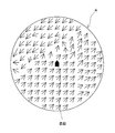
- FIG. 2 is a diagram illustrating an example of a wavefront velocity vector at each point in the calculation target area A displayed on the second display 4b.
- the magnitude of the wavefront velocity vector at each point is represented by the size of the arrow displayed at each corresponding point, and the direction of the wavefront velocity vector at each point is displayed at each corresponding point. It is represented by the direction of the arrow.
- the flow direction change point estimation unit 12 is configured to estimate a flow direction change point.
- the flow direction change point is a point between the adjacent wave front velocity vectors when the angular difference between the flow directions of the wave front velocity vectors adjacent in position is equal to or larger than a predetermined angle difference.
- the flow direction change point estimator 12 is adjacent to the azimuth direction (radial direction centered on the ship) within a predetermined range within a predetermined distance from the ship (hereinafter referred to as a calculation target area A) centered on the ship. Two wavefront velocity vectors are set as determination target vectors.
- the flow direction change point estimation unit 12 determines whether or not the angle difference between the flow directions of all the determination target vectors in the calculation target area A is equal to or larger than a predetermined angle, and the flow direction change point in the calculation target area A Is estimated.
- the tide estimator 13 estimates the tide based on the flow direction change point estimated by the flow direction change point estimator 12.
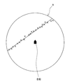
- the tide estimator 13 calculates an approximate function of a plurality of flow direction change points estimated by the flow direction change point estimator 12 by, for example, the least square method, and estimates the approximate function as a tide.
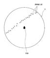
- FIG. 3 is a diagram showing a display example of the tide estimated by the tide estimation unit 13 displayed on the second display 4b. As shown in FIG. 3, the tide is displayed by displaying the approximate function estimated by the tide estimation unit 13 together with all the flow direction change points estimated by the flow direction change point estimation unit 12 on the second display 4b. Is done.
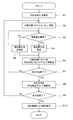
- FIG. 4 is a flowchart for explaining the operation of the tide estimation device 10.
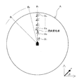
- FIG. 5 is a diagram for explaining the operation of the tide estimation device 10 and shows only a part of wavefront velocity vectors. With reference to FIG.4 and FIG.5, the process at the time of estimating a tide is demonstrated.
- step S1 the tide estimation device 10 sets an azimuth direction ( ⁇ 1 in the case of FIG. 5) around the ship.
- tide estimation device 10 sets the two wavefronts velocity vectors which are adjacent to each other along the azimuthal direction theta 1 for comparison vector.
- tide estimating apparatus 10 as shown in FIG. 5, the wave front velocity vector X 1 closest to along and ship concerned azimuthally theta 1, distant of the wave front velocity vectors X 1 and the azimuth direction theta 1 the wave front velocity vector X 2 adjacent to the side, and set as a comparison target vector.
- step S3 the flow direction change point estimation unit 12 determines whether or not the angle difference between the comparison target vectors is equal to or greater than a predetermined threshold value.
- Flow directions change point estimation unit 12 if the angular difference between the comparison vector is equal to or greater than the threshold value (Yes in step S3), the flow of the midpoint of the wave front velocity vectors X 1 and X 2 constituting the comparison target vector direction change point (Step S4), and the process proceeds to step S6.
- the flow direction changing point estimation unit 12 if the angle difference compared vector is less than the threshold value (No in step S3), and estimates that there is no flow directions change point between the wave front velocity vectors X 1 and X 2 (Step S5), the process proceeds to Step S6.
- the threshold value is a predetermined value and is stored in the flow direction change point estimation unit 12. This threshold is a value set empirically or experimentally. Note that the tide estimation device may be configured so that the user can change the threshold by inputting the threshold using a control panel (not shown) or the like.
- step S6 the tide estimation device 10 shifts the comparison target vector in the azimuth direction and resets it. Specifically, in the case of FIG. 5, the tide estimation device 10 shifts the comparison target vector, which has been most recently determined whether or not there is a flow direction change point, by one to the far side in the azimuth direction, and the wavefront velocity vector X 2. and X 3, is set as a new comparison target vector.
- Step S7 when the above determination is completed for all wavefront velocity vectors in a predetermined azimuth direction in Step S7 (Yes in Step S7), the process proceeds to Step S8. On the other hand, if the above determination has not been completed for all wavefront velocity vectors in the predetermined azimuth direction in step S7 (No in step S7), the process returns to step S3, and the comparison target vector reset in step S6 It is determined whether or not the angle difference of the comparison target vectors is equal to or greater than a predetermined threshold.
- step S8 the tide estimation device 10 sets a new azimuth direction by shifting the azimuth direction by a predetermined angle. Specifically, in the case of FIG. 5, after the existence of countercurrent change point flow for all the compared vectors along the azimuth direction theta 1 is estimated, shifting the azimuth direction theta 2.
- step S9 when the estimation of the flow direction change point is completed for all azimuth directions (Yes in step S9), the process proceeds to step S10.
- step S9 when the estimation of the flow direction change point is not completed for all the azimuth directions in Step S9 (No in Step S9), the process returns to Step S2. Then, the tide estimator 10 sets the comparison target vector as described above for the newly set azimuth direction, and performs the above determination.
- step S9 When the above-described flow from step S1 to step S9 is repeated and the estimation of the flow direction change point for each point in the calculation target area A is completed (Yes in step S9), the tide estimator 13 estimates the tide.
- FIG. 6 is a graph for explaining a tide estimation method derived from a plurality of flow direction change points estimated as described above.
- the tide estimation unit 13 calculates an approximate function of a plurality of flow direction change points by, for example, the least square method, and estimates the approximate function as a tide.
- the approximate function include a linear function, a quadratic function, and the like.
- the approximate function is not limited thereto, and other functions may be used.
- the tide estimated as described above is displayed on the second display 4b together with a plurality of flow direction change points as shown in FIG. As a result, the user can visually recognize the tide position relative to the ship.
- the display state on the second display 4b is not limited to that shown in FIG. 3, but only the tides may be displayed without displaying the flow direction change point, for example, as shown in FIG.
- the tide estimation device 10 can estimate the distribution state of flow direction change points in a short time.
- the tide estimation device 10 can appropriately estimate the tide based on a plurality of flow direction change points.
- the tide estimation device 10 can estimate the tide based on the approximate function of a plurality of flow direction change points, the tide can be estimated relatively easily.
- the tide estimated by the tide estimation apparatus 10 is displayed on the second display 4b. Therefore, the user can visually recognize the tides appropriately.
- FIG. 8 is a block diagram showing a configuration of a radar apparatus 1a according to a modification.
- the radar apparatus 1a according to the present modification has a configuration in which a flow direction change point estimation apparatus 10a is provided instead of the tide estimation apparatus, unlike the above embodiment.
- the flow direction change point estimation device 10a has a configuration in which the tide estimation unit is omitted in the tide estimation device of the above embodiment.
- the flow direction change point estimation unit 12 of this modification example estimates a plurality of flow direction change points in the calculation target area A in the same manner as the flow direction change point estimation unit of the above embodiment.
- FIG. 9 is a diagram showing a display example of a plurality of flow direction change points estimated by the flow direction change point estimation unit 12 displayed on the second display 4b.
- an X mark is displayed at the position where the flow direction change point is estimated.
- the flow direction change point estimation device 10a estimates the flow direction change point in the same manner as in the above embodiment. In this way, when estimating the distribution state of the flow direction change points, it is not necessary to move the own ship equipped with the tide estimation device in the area as in the prior art.
- the flow direction change point estimation device 10a can estimate the distribution state of the flow direction change points in a short time.
- a plurality of flow direction change points estimated by the flow direction change point estimation device 10a are displayed on the second display 4b. Therefore, the user can visually recognize the flow direction change point appropriately.
- a plurality of flow direction change points estimated at each point in the calculation target area A are displayed on the second display 4b. In this way, the user can estimate that a portion where a plurality of flow direction change points are gathered is a tide.
- the comparison target vector set for estimating the flow direction change point is the diameter in each of the azimuth directions around the ship. Set sequentially along the direction. That is, in the tide estimation device 10 according to the above embodiment, the flow direction change point is estimated based on the r- ⁇ coordinate.
- the present invention is not limited to this, and the flow direction change point may be estimated based on the xy coordinates as shown in FIG. In this case, for example, as an example, a virtual straight line extending in the x direction in the calculation target area A is set, a comparison target vector is sequentially set along the virtual straight line, and the flow direction change point is estimated.
- the virtual line is shifted in the y direction, a comparison target vector is set along the shifted virtual line in the same manner as described above, and the flow direction change point is estimated.
- the flow direction change point can be estimated in the calculation target area A as in the case of the above embodiment.
- FIG. 11 is a block diagram showing a configuration of a radar apparatus 1b according to a modification.
- the wavefront flow calculation unit 11 is calculated based on the optical flow.
- the present invention is not limited to this, and the wavefront flow calculation unit 11 may calculate the wavefront flow calculation unit 11 by Doppler measurement.
- the wavefront flow calculation unit 11a according to this modification includes, for example, a reflected wave of the pulse wave transmitted from the antenna 5 at the first timing, and a reflected wave of the pulse wave transmitted from the antenna 5 at the second timing, The wavefront velocity vector at each point in the calculation target area A is calculated on the basis of the frequency difference.
- the second display 4b for displaying the flow direction change point and the tide is provided as a display unit separate from the first display 4a for displaying an echo image of another ship or the like.
- the display may be superimposed on the same display unit.
- the tide is displayed on the display part of the radar apparatus 1, you may display on the display part of the sonar apparatus which detects not only this but a fish school etc., for example. Thereby, the trend of the school of fish can be predicted using the tide as a clue.
- FIG. 12 is a block diagram showing a configuration of the personal computer 9 having the radar device 1c and the tide estimation device 10 according to the modification.
- the tide estimation device 10 may be provided in a personal computer 9 separate from the radar device 1b. In this case, what is necessary is just to display on the 2nd display 4b comprised with the display of the personal computer 9 the tide which is a calculation result in the tide estimation apparatus 10.
- FIG. 12 is a block diagram showing a configuration of the personal computer 9 having the radar device 1c and the tide estimation device 10 according to the modification.
- the tide estimation device 10 may be provided in a personal computer 9 separate from the radar device 1b. In this case, what is necessary is just to display on the 2nd display 4b comprised with the display of the personal computer 9 the tide which is a calculation result in the tide estimation apparatus 10.
- the flow direction change point is estimated based on the angle difference between adjacent wavefront velocity vectors.
- the flow direction is changed based on the echo level of the adjacent wavefront velocity vector.
- a change point can also be estimated.
- the present invention can be widely applied as a flow direction change point estimation device, a tide estimation device, a radar device equipped with this tide estimation device, a tide estimation method for estimating a tide, and a tide estimation program.
Landscapes
- Engineering & Computer Science (AREA)
- Radar, Positioning & Navigation (AREA)
- Remote Sensing (AREA)
- Physics & Mathematics (AREA)
- Computer Networks & Wireless Communication (AREA)
- General Physics & Mathematics (AREA)
- Ocean & Marine Engineering (AREA)
- Electromagnetism (AREA)
- Radar Systems Or Details Thereof (AREA)
Abstract
[Problème] Estimer rapidement un état de distribution de points de changement de direction de courant. [Solution] La solution selon l'invention est un dispositif (10a) permettant d'estimer des points de changement de direction de courant, le dispositif comprenant : une unité de dérivation (11) servant à dériver des vecteurs de vitesse de crête de vague, c'est-à-dire des vecteurs de vitesse de crête de vague sur la surface de l'eau à chaque point dans un intervalle prédéterminé ; et une unité (12) servant à estimer des points de changement de direction de courant, qui estime une pluralité de points de changement de direction de courant en comparant des différences angulaires entre des vecteurs de vitesse de crête de vague voisins parmi les vecteurs de vitesse de crête de vague à chaque point qui sont dérivés par l'unité de dérivation (11) et, quand la différence angulaire est au moins une valeur prédéterminée, estime qu'une position entre les vecteurs de vitesse de crête de vague voisins est un point de changement de la direction de l'instant.
Applications Claiming Priority (2)
| Application Number | Priority Date | Filing Date | Title |
|---|---|---|---|
| JP2013115789 | 2013-05-31 | ||
| JP2013-115789 | 2013-05-31 |
Publications (1)
| Publication Number | Publication Date |
|---|---|
| WO2014192529A1 true WO2014192529A1 (fr) | 2014-12-04 |
Family
ID=51988566
Family Applications (1)
| Application Number | Title | Priority Date | Filing Date |
|---|---|---|---|
| PCT/JP2014/062657 Ceased WO2014192529A1 (fr) | 2013-05-31 | 2014-05-13 | Dispositif, procédé et programme d'estimation de points de changement de direction de courant, dispositif d'estimation de ride de courant et dispositif radar |
Country Status (1)
| Country | Link |
|---|---|
| WO (1) | WO2014192529A1 (fr) |
Cited By (1)
| Publication number | Priority date | Publication date | Assignee | Title |
|---|---|---|---|---|
| CN104849491A (zh) * | 2015-04-28 | 2015-08-19 | 奇瑞汽车股份有限公司 | 水流流速检测方法及系统 |
Citations (4)
| Publication number | Priority date | Publication date | Assignee | Title |
|---|---|---|---|---|
| JPS5967462A (ja) * | 1982-10-09 | 1984-04-17 | Furuno Electric Co Ltd | 航跡および潮流状況の表示装置 |
| JPH03262990A (ja) * | 1990-03-13 | 1991-11-22 | Tech Res & Dev Inst Of Japan Def Agency | 波浪観測レーダ |
| JPH11237477A (ja) * | 1998-02-20 | 1999-08-31 | Nagano Japan Radio Co | 短波または超短波を用いた海洋レーダおよび短波または超短波を用いた海洋レーダシステム |
| JP2009300207A (ja) * | 2008-06-12 | 2009-12-24 | Nagano Japan Radio Co | 海洋レーダ局および海洋レーダ観測装置 |
-
2014
- 2014-05-13 WO PCT/JP2014/062657 patent/WO2014192529A1/fr not_active Ceased
Patent Citations (4)
| Publication number | Priority date | Publication date | Assignee | Title |
|---|---|---|---|---|
| JPS5967462A (ja) * | 1982-10-09 | 1984-04-17 | Furuno Electric Co Ltd | 航跡および潮流状況の表示装置 |
| JPH03262990A (ja) * | 1990-03-13 | 1991-11-22 | Tech Res & Dev Inst Of Japan Def Agency | 波浪観測レーダ |
| JPH11237477A (ja) * | 1998-02-20 | 1999-08-31 | Nagano Japan Radio Co | 短波または超短波を用いた海洋レーダおよび短波または超短波を用いた海洋レーダシステム |
| JP2009300207A (ja) * | 2008-06-12 | 2009-12-24 | Nagano Japan Radio Co | 海洋レーダ局および海洋レーダ観測装置 |
Cited By (1)
| Publication number | Priority date | Publication date | Assignee | Title |
|---|---|---|---|---|
| CN104849491A (zh) * | 2015-04-28 | 2015-08-19 | 奇瑞汽车股份有限公司 | 水流流速检测方法及系统 |
Similar Documents
| Publication | Publication Date | Title |
|---|---|---|
| JP6258310B2 (ja) | 引き波検出装置、レーダ装置、引き波検出方法、及び引き波検出プログラム | |
| JP5072400B2 (ja) | 水中探知装置 | |
| EP3196669B1 (fr) | Appareil radar et procédé de suivi d'objet cible | |
| WO2017204075A1 (fr) | Dispositif de traitement de signal et dispositif radar | |
| JP6404212B2 (ja) | 表層潮流推定装置、レーダ装置、表層潮流推定方法、及び表層潮流推定プログラム | |
| JP2009300207A (ja) | 海洋レーダ局および海洋レーダ観測装置 | |
| JP6469357B2 (ja) | 水中探知装置、水中探知方法、および水中探知プログラム | |
| JP2016206153A (ja) | 信号処理装置、及びレーダ装置 | |
| JP2015014471A (ja) | エコー信号処理装置、波浪レーダ装置、エコー信号処理方法、及びエコー信号処理プログラム | |
| JP2016169968A (ja) | 表層潮流推定装置、レーダ装置、表層潮流推定方法、及び表層潮流推定プログラム | |
| JP6154219B2 (ja) | エコー信号処理装置、波浪レーダ装置、エコー信号処理方法、及びエコー信号処理プログラム | |
| WO2014192532A1 (fr) | Dispositif de détection d'informations d'environnement pour navires, dispositif de spécification d'itinéraire, procédé de détection d'informations d'environnement pour navires, et programme | |
| JP6392217B2 (ja) | 航行支援装置、航行支援方法、および、プログラム | |
| JP6084811B2 (ja) | 追尾処理装置、及び追尾処理方法 | |
| JP2015232509A (ja) | 信号処理装置、レーダ装置、信号処理方法、及び信号処理プログラム | |
| JP2010145224A (ja) | スキャニングソナー装置 | |
| JP3129749U (ja) | 水中探知装置 | |
| JP6339074B2 (ja) | 海象検出装置、レーダ装置、海象検出方法、および、プログラム | |
| JP6757083B2 (ja) | 音響測深装置及びマルチビーム音響測深装置 | |
| JP6466768B2 (ja) | レーダ装置 | |
| JP2014235049A (ja) | 波頭速度分布推定装置、波頭速度分布推定方法、及び波頭速度分布推定プログラム | |
| JP6311230B2 (ja) | 目標物検出装置、目標物検出方法、プログラム及び記録媒体 | |
| JP2013181943A (ja) | 海面流観測装置 | |
| EP4180841B1 (fr) | Dispositif et procédé de détection de cible | |
| JP6180004B2 (ja) | 追尾処理装置、及び追尾処理方法 |
Legal Events
| Date | Code | Title | Description |
|---|---|---|---|
| 121 | Ep: the epo has been informed by wipo that ep was designated in this application |
Ref document number: 14803522 Country of ref document: EP Kind code of ref document: A1 |
|
| NENP | Non-entry into the national phase |
Ref country code: DE |
|
| 122 | Ep: pct application non-entry in european phase |
Ref document number: 14803522 Country of ref document: EP Kind code of ref document: A1 |
|
| NENP | Non-entry into the national phase |
Ref country code: JP |