WO2014192533A1 - Joint à rotule - Google Patents
Joint à rotule Download PDFInfo
- Publication number
- WO2014192533A1 WO2014192533A1 PCT/JP2014/062674 JP2014062674W WO2014192533A1 WO 2014192533 A1 WO2014192533 A1 WO 2014192533A1 JP 2014062674 W JP2014062674 W JP 2014062674W WO 2014192533 A1 WO2014192533 A1 WO 2014192533A1
- Authority
- WO
- WIPO (PCT)
- Prior art keywords
- ball
- holder
- mechanical element
- support shaft
- shaft
- Prior art date
- Legal status (The legal status is an assumption and is not a legal conclusion. Google has not performed a legal analysis and makes no representation as to the accuracy of the status listed.)
- Ceased
Links
Images


Classifications
-
- F—MECHANICAL ENGINEERING; LIGHTING; HEATING; WEAPONS; BLASTING
- F16—ENGINEERING ELEMENTS AND UNITS; GENERAL MEASURES FOR PRODUCING AND MAINTAINING EFFECTIVE FUNCTIONING OF MACHINES OR INSTALLATIONS; THERMAL INSULATION IN GENERAL
- F16C—SHAFTS; FLEXIBLE SHAFTS; ELEMENTS OR CRANKSHAFT MECHANISMS; ROTARY BODIES OTHER THAN GEARING ELEMENTS; BEARINGS
- F16C11/00—Pivots; Pivotal connections
- F16C11/04—Pivotal connections
-
- F—MECHANICAL ENGINEERING; LIGHTING; HEATING; WEAPONS; BLASTING
- F16—ENGINEERING ELEMENTS AND UNITS; GENERAL MEASURES FOR PRODUCING AND MAINTAINING EFFECTIVE FUNCTIONING OF MACHINES OR INSTALLATIONS; THERMAL INSULATION IN GENERAL
- F16C—SHAFTS; FLEXIBLE SHAFTS; ELEMENTS OR CRANKSHAFT MECHANISMS; ROTARY BODIES OTHER THAN GEARING ELEMENTS; BEARINGS
- F16C11/00—Pivots; Pivotal connections
- F16C11/04—Pivotal connections
- F16C11/06—Ball-joints; Other joints having more than one degree of angular freedom, i.e. universal joints
- F16C11/0619—Ball-joints; Other joints having more than one degree of angular freedom, i.e. universal joints the female part comprising a blind socket receiving the male part
- F16C11/0623—Construction or details of the socket member
-
- F—MECHANICAL ENGINEERING; LIGHTING; HEATING; WEAPONS; BLASTING
- F16—ENGINEERING ELEMENTS AND UNITS; GENERAL MEASURES FOR PRODUCING AND MAINTAINING EFFECTIVE FUNCTIONING OF MACHINES OR INSTALLATIONS; THERMAL INSULATION IN GENERAL
- F16C—SHAFTS; FLEXIBLE SHAFTS; ELEMENTS OR CRANKSHAFT MECHANISMS; ROTARY BODIES OTHER THAN GEARING ELEMENTS; BEARINGS
- F16C11/00—Pivots; Pivotal connections
- F16C11/04—Pivotal connections
- F16C11/06—Ball-joints; Other joints having more than one degree of angular freedom, i.e. universal joints
- F16C11/0619—Ball-joints; Other joints having more than one degree of angular freedom, i.e. universal joints the female part comprising a blind socket receiving the male part
- F16C11/0623—Construction or details of the socket member
- F16C11/0628—Construction or details of the socket member with linings
- F16C11/0633—Construction or details of the socket member with linings the linings being made of plastics
-
- F—MECHANICAL ENGINEERING; LIGHTING; HEATING; WEAPONS; BLASTING
- F16—ENGINEERING ELEMENTS AND UNITS; GENERAL MEASURES FOR PRODUCING AND MAINTAINING EFFECTIVE FUNCTIONING OF MACHINES OR INSTALLATIONS; THERMAL INSULATION IN GENERAL
- F16C—SHAFTS; FLEXIBLE SHAFTS; ELEMENTS OR CRANKSHAFT MECHANISMS; ROTARY BODIES OTHER THAN GEARING ELEMENTS; BEARINGS
- F16C11/00—Pivots; Pivotal connections
- F16C11/04—Pivotal connections
- F16C11/06—Ball-joints; Other joints having more than one degree of angular freedom, i.e. universal joints
- F16C11/0685—Manufacture of ball-joints and parts thereof, e.g. assembly of ball-joints
-
- F—MECHANICAL ENGINEERING; LIGHTING; HEATING; WEAPONS; BLASTING
- F16—ENGINEERING ELEMENTS AND UNITS; GENERAL MEASURES FOR PRODUCING AND MAINTAINING EFFECTIVE FUNCTIONING OF MACHINES OR INSTALLATIONS; THERMAL INSULATION IN GENERAL
- F16C—SHAFTS; FLEXIBLE SHAFTS; ELEMENTS OR CRANKSHAFT MECHANISMS; ROTARY BODIES OTHER THAN GEARING ELEMENTS; BEARINGS
- F16C11/00—Pivots; Pivotal connections
- F16C11/04—Pivotal connections
- F16C11/06—Ball-joints; Other joints having more than one degree of angular freedom, i.e. universal joints
- F16C11/0695—Mounting of ball-joints, e.g. fixing them to a connecting rod
-
- F—MECHANICAL ENGINEERING; LIGHTING; HEATING; WEAPONS; BLASTING
- F16—ENGINEERING ELEMENTS AND UNITS; GENERAL MEASURES FOR PRODUCING AND MAINTAINING EFFECTIVE FUNCTIONING OF MACHINES OR INSTALLATIONS; THERMAL INSULATION IN GENERAL
- F16C—SHAFTS; FLEXIBLE SHAFTS; ELEMENTS OR CRANKSHAFT MECHANISMS; ROTARY BODIES OTHER THAN GEARING ELEMENTS; BEARINGS
- F16C3/00—Shafts; Axles; Cranks; Eccentrics
- F16C3/02—Shafts; Axles
-
- F—MECHANICAL ENGINEERING; LIGHTING; HEATING; WEAPONS; BLASTING
- F16—ENGINEERING ELEMENTS AND UNITS; GENERAL MEASURES FOR PRODUCING AND MAINTAINING EFFECTIVE FUNCTIONING OF MACHINES OR INSTALLATIONS; THERMAL INSULATION IN GENERAL
- F16C—SHAFTS; FLEXIBLE SHAFTS; ELEMENTS OR CRANKSHAFT MECHANISMS; ROTARY BODIES OTHER THAN GEARING ELEMENTS; BEARINGS
- F16C2322/00—Apparatus used in shaping articles
- F16C2322/50—Hand tools, workshop equipment or manipulators
- F16C2322/59—Manipulators, e.g. robot arms
Definitions
- the present invention relates to a ball joint used for various link devices such as a link motion mechanism of an industrial robot.
- Patent Document 1 As this type of ball joint, one disclosed in Patent Document 1 is known.
- the ball joint disclosed in this document includes a ball stud having a ball portion serving as a rocking center of the link mechanism at the tip of the shaft member, and a slid on the spherical surface of the ball covering the maximum diameter portion of the ball stud. And a holder in contact therewith.
- a mechanical element such as a link member is connected to the shaft member of the ball stud, while a fixing portion for connecting another mechanical element is provided to the holder. That is, such a ball joint connects two mechanical elements so as to be swingable and serves as a center of swinging, and these mechanical elements are often used for the purpose of constituting a link device such as a parallel link.
- Such a conventional ball joint connects two mechanical elements and forms one swing center between them.
- the third machine element is swingably connected to the two machine elements connected by the ball joint, and the swing center of the third machine element is There are cases where it is desired to provide the ball joint near the ball portion.
- the conventional ball joint does not have a third machine element connecting portion, and the third machine element has to be connected to another machine element directly connected to the ball joint. For this reason, the swing center of the third mechanical element has to be provided at a position away from the swing center of the ball joint, and the degree of freedom in designing the link device is limited.
- the present invention has been made in view of such a problem, and an object of the present invention is to provide a third mechanical element in the vicinity of the swing center of the first and second mechanical elements that are swingably connected to each other.
- An object of the present invention is to provide a ball joint that can be pivotably connected and can be produced at low cost.
- the ball joint of the present invention that achieves the above object has a shaft member to which a first mechanical element is coupled, a ball stud having a ball portion at the tip of the shaft member, and a casting having the ball portion as a core.
- the first machine element and the second machine element having a fixed part to which the second machine element is coupled, and having the ball part as a swing center.
- a third mechanical element connecting portion that protrudes from the holder in a direction intersecting the shaft member of the ball stud and forms a second swinging center different from the ball portion.
- a swing support shaft that is integrated with the holder when the holder is cast.
- the holder is formed by casting with the ball portion of the ball stud as the core, and the holder and the swing support shaft are integrated during the casting, and the swing support shaft is the ball stud. Projecting from the holder in a direction intersecting with the shaft member to form a third mechanical element connecting portion and forming a second swing center different from the ball portion. Therefore, by using the ball joint of the present invention, it is possible to easily connect the third machine element in a swingable manner to the vicinity of the swing center of the first and second machine elements, In addition, since the swing support shaft is embedded and fixed in the holder when the holder is cast, the second swing center can be added to the existing ball joint at low cost.
- FIG. 2 is a sectional view of the ball joint shown in FIG. 1 taken along the line II-II. It is a perspective view which shows an example of a rocking
- FIG. 5 is a cross-sectional view taken along line VV in FIG. 4. It is a figure which shows the usage example of the ball joint of this invention.
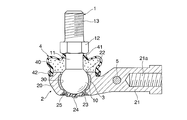
- FIG. 1 and 2 show an example of an embodiment of a ball joint to which the present invention is applied
- FIG. 1 is a perspective view showing an appearance
- FIG. 2 is a sectional view taken along line II-II in FIG.
- the ball joint includes a ball stud 1 having a ball portion 10 at the tip of a shaft member 11, a resin sliding contact member 3 that is covered with the ball portion 10 and that is in sliding contact with the ball portion 10, and the resin sliding contact member.
- the ball stud 1 is swingably coupled to the holder 2, and the swing center is the ball portion 10 of the ball stud 1. Therefore, by fixing the first mechanical element to the ball stud 1 and the second mechanical element to the holder 2, the mechanical elements are pivotably connected around the ball portion 10 as a swing center. Is possible.
- the swing support shaft 5 can be used to connect the third machine element, and the holder and the third machine element can swing freely with the swing support shaft 5 as the second swing center. It is also possible to connect to.
- the ball stud 1 is formed, for example, by electric resistance welding of a rod-shaped shaft member 11 to a steel ball for a bearing having a high sphericity that becomes the ball portion 10.
- the ball stud in which the ball portion 10 and the shaft member 11 are integrated can be formed by plastic working such as cold forging.
- the shaft member 11 is formed with a flange portion 12 having a seating surface for fixing a first mechanical element such as a link member, and a male screw on the opposite side of the ball portion 10 across the flange portion 12. 13 is formed.
- the said collar part 12 is formed in the shape of a hexagon nut, and it is possible to fasten the external thread 13 of the said ball stud 1 to a 1st machine element by using a spanner wrench.
- the resin sliding contact member 3 is formed in an annular shape covering the maximum diameter portion of the ball portion 10 and covers approximately 2/3 of the spherical surface of the ball portion 10. That is, two openings are formed in the resin sliding contact member 3 in opposite directions, and the spherical surface of the ball part 10 protrudes from these openings.
- a concave spherical resin sliding contact surface 30 that substantially matches the spherical surface of the ball portion 10 is formed on the inner peripheral surface of the resin sliding contact member 3, and the resin sliding contact member 3 is fixed to the holder 2.
- the ball stud 1 can swing with respect to the holder 2 by the sliding contact between the spherical surface of the ball portion 10 and the resin sliding contact surface 30.
- polyether ether ketone product of Victrex plc / trade name: PEEK
- the thickness thereof is, for example, about 1.0 mm.
- the holder 2 includes a main body 20 provided around the resin sliding contact member 3 and a fixing portion for coupling the main body 20 to a second mechanical element such as a link member. 21, and the main body 20 and the fixing portion 21 are integrally formed by die casting of an aluminum alloy or a zinc alloy.
- the fixing portion 21 is formed with a female screw 21a so that a male screw formed on the second mechanical element can be coupled.
- the main body portion 20 of the holder 2 is formed in an annular shape outside the resin sliding contact member 3, and the resin sliding contact member 3 is fixed to the main body portion 20.
- Two openings 22 and 23 are formed in the main body 20 so as to coincide with a pair of openings provided in the resin sliding contact member 3.
- One opening 22 defines the swing range of the ball stud 1, and the other opening 23 is closed by a closing cap 24.
- the body portion 20 is not in contact with the ball portion 10 of the ball stud 1, and the resin sliding contact member 3 is slightly between the body portion 20 and the ball portion 10 in any of the openings 22 and 23. Is exposed.
- the opening 23 of the holder 2 is closed with a closing cap 24, and a grease reservoir 25 is formed in the opening 23.
- the swing support shaft 5 is a columnar member formed by cutting or forging, and penetrates the fixed portion of the holder 2.
- the center portion of the swinging support shaft 5 is fixed by being buried in the fixing portion 21 of the holder 2 at the time of die casting of the holder 2, whereby the swinging support shaft 5 and the holder 2 are fixed. It is integrated.
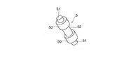
- FIG. 3 is a perspective view showing the swing support shaft 5.
- the swing support shaft 5 includes a fixed shaft portion 50 and a pair of tip shaft portions 51 protruding from both ends of the fixed shaft portion 50 in the axial direction. As can be seen from FIG. 1, both ends of the fixed shaft portion 50 slightly protrude from the fixed portion 21 of the holder 2, and the tip shaft portion 51 protrudes completely from the holder 2.
- the center axis of the swing support shaft 5 is perpendicular to the center axis of the ball stud 1 in a state where the ball stud 1 is raised at the center of the swingable range, that is, the center of the opening 22 of the holder 2. It extends in the direction.
- the distance between the center axis of the swing support shaft 5 and the center of the ball portion of the ball stud 1 can be arbitrarily set.
- the outer diameter of the tip shaft portion 51 of the swing support shaft 5 is smaller than the outer diameter of the fixed shaft portion 50, and the outer diameter tolerance is set in consideration of the fit with the inner diameter of a commercially available rotary bearing. ing. Further, the shaft centers of the pair of distal end shaft portions 50 projecting on both sides of the holder 2 coincide with each other. Further, a locking groove 52 is formed in the center of the fixed shaft portion 50 in the axial direction, and the locking groove 52 is buried in the fixed portion 21 of the holder 2 which is die-cast. . That is, due to the presence of the locking groove 52, the swing support shaft 5 does not come out from the fixing portion 21 of the holder 2 in the axial direction, and is firmly fixed to the fixing portion 21.
- a boot seal 4 is attached between the outer peripheral edge of the main body portion 20 of the holder 2 and the shaft member 11 of the ball stud 1, and the ball portion 10 of the ball stud 1 and the main body portion 20 of the holder 2
- a seal pocket 40 for accommodating a lubricant such as grease is formed.
- the end 41 on the ball stud 1 side of the boot seal 4 is in close contact with the shaft member 11 due to its elasticity, while the end 42 on the holder 2 side is sandwiched between the outer peripheral edge of the holder 2 by a locking ring. Therefore, the ball stud 1 does not come off even when the ball stud 1 swings.
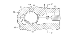
- FIG. 4 is a cross-sectional view showing a process of die-casting the holder. Inside the casting molds 6A, 6B and 6C, a bearing steel ball 10A to be the ball portion 10 of the ball stud 1 and the resin sliding contact member 3 are shown. The state where the swing support shaft 5 is set as a core is shown.
- the resin sliding contact member 3 is mounted on the bearing steel ball 10A in advance.
- the resin sliding contact member 3 is injection molded using the bearing steel ball 10A as a core, and the molding of the resin sliding contact member 3 and the bearing steel are performed. It is conceivable to mount the ball 10A in one process. Thus, if the resin sliding contact member 3 is formed using the bearing steel ball 10A itself as a core, the mounting effort to the bearing steel ball 10A is omitted, and the spherical surface of the bearing steel ball 10A is replaced with the resin sliding contact.
- the resin sliding contact surface 3 of the contact member 3 is transferred to the resin sliding contact surface 30, the resin sliding contact member 3 and the bearing steel ball 10 ⁇ / b> A are in surface contact with no gap, and the ball portion 10 of the ball stud and the resin sliding contact member 3 later The contact state can be improved.
- the resin sliding contact member may be formed separately from the bearing steel ball, and the molded resin sliding contact member 3 may be mounted on the bearing steel ball 10A.
- the bearing steel ball 10A in which the resin sliding contact member 3 is attached to the inside of the mold dies 6A and 6B that are opened and the swing support shaft 5 are set as a core. After that, these casting molds are closed, and the resin sliding contact member 3, the bearing steel balls 10 and the swing support shaft 5 are fixed at predetermined positions as shown in FIG. From this state, a molten aluminum alloy or zinc alloy is press-fitted into the cavity 7 in the mold.
- symbol 6C in FIG. 4 is a core which provides the pilot hole for internal threads 21a with respect to the main-body part of a holder.
- the ball 10A for bearings has a spherical surface protruding from the resin sliding contact member 3 fitted into concave spherical support seats 60 and 61 formed on the molds 6A and 6B.
- the peripheral edge is in contact with the peripheral edge of the resin sliding contact member 3.
- the main body portion 20 of the holder 2 in which the bearing steel ball 10A is wrapped with the alloy from the outside of the resin sliding contact member 3 is cast, and the main body portion 20 is moved by the resin sliding contact member 3 to the bearing steel ball 10A.
- the bearing steel ball 10 ⁇ / b> A is kept out of contact with the main body 20.
- the resin sliding contact member 3 since the outer peripheral surface of the resin sliding contact member 3 facing the cavity 7 is in contact with a high temperature alloy during the casting, the resin sliding contact member 3 is fixed to the main body 20 of the cast holder 2. Become. Since the maximum diameter portion of the bearing steel ball 10A is covered with the resin sliding contact member 3, when the resin sliding contact member 3 is fixed to the main body portion 20 of the holder 2, the bearing steel ball 10A is The holder 2 is held in a state where it cannot be detached.
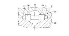
- FIG. 5 is a cross-sectional view taken along the line VV of FIG.
- the swing support shaft 5 is fixed by casting dies 6A and 6B, and the inside of the cavity 7 formed by mold clamping is placed inside the swing support shaft 5.
- the casting molds 6A and 6B sandwich a part of the fixed shaft portion 50 of the swing support shaft 5 and the tip shaft portion 51, and the fixed shaft portion 50 including the locking groove 52 in the cavity 7 is inserted. Some are present. Therefore, when the molten alloy is poured into the cavity 7 to cast the holder 2, the swing support shaft 5 is embedded in the fixing portion 21 of the holder 2.
- both ends of the swing support shaft 5 covered by the casting molds 6A and 6B that is, a part of the fixed shaft part 50 and the tip shaft part 51 protrude.
- the lock groove 52 acts as a retaining member, and the swing support shaft 5 Does not slip out of the holder 2 in the axial direction.
- the shaft member 11 is welded to the bearing steel ball 10A.
- projection welding which is a kind of electric resistance welding, can be used.
- the electrode is brought into contact with the bearing steel ball 10A from the opening 23 formed in the holder 2, while the electrode is also brought into contact with the shaft member 11, and these bearing steel balls are brought into contact with each other.
- a welding current is passed between 10A and the shaft member 11. Thereby, the ball stud 1 in which the bearing steel ball 10A is joined to the tip of the shaft member 11 as the ball portion 10 is completed.
- FIG. 6 is a schematic view showing an example of use of the ball joint of the present invention.
- a first mechanical element 80 is coupled to the ball stud 1
- a second mechanical element 81 is coupled to the holder 2, and the first mechanical element 80 and the second mechanical element 81 are coupled to the ball portion of the ball stud 1.
- 10 is pivotably connected with a rocking center as a center.
- a third mechanical element 82 is swingably coupled to the swing support shaft 5 fixed to the holder 2 via a bearing, and the swing support shaft 5 is separate from the ball portion 10.
- the second oscillation center is configured.
- the swing support shaft 5 serving as the second swing center is integrated with the holder 2, the first mechanical elements connected by the ball joint are used. It is possible to easily add the third machine element 82 to the 80 and the second machine element 81 to configure the link device. Moreover, since the swing support shaft 5 serving as the second swing center can be disposed in the vicinity of the ball portion 10 serving as the swing center of the first machine element 80 and the second machine element 81, the link device. It becomes possible to increase the degree of freedom of design.
- the swing support shaft 5 is integrated with the holder 2 when the holder 2 is cast, it becomes possible to add a second swing center to the existing ball joint at low cost. Ball joints that can be used in various link devices can be produced at low cost.
Landscapes
- Engineering & Computer Science (AREA)
- General Engineering & Computer Science (AREA)
- Mechanical Engineering (AREA)
- Ocean & Marine Engineering (AREA)
- Pivots And Pivotal Connections (AREA)
Abstract
Cette invention concerne un joint à rotule permettant de relier en pivotement un troisième élément mécanique à proximité d'un centre de pivot d'un premier et d'un deuxième élément mécanique qui sont reliés pivotants l'un à l'autre, ledit joint à rotule comprenant : un pivot à rotule (1) présentant un élément formant arbre (11) auquel est relié un premier élément mécanique (80), comprenant une section formant rotule (10) à une extrémité distale de l'élément formant arbre (11) ; un support (2) comprenant une section de fixation à laquelle est relié un deuxième élément mécanique (81) et qui est moulé par coulée, la section formant rotule (10) constituant le noyau du moulage, ledit support recouvrant une section de diamètre maximal de la section formant bille et accouplant de manière pivotante le premier élément mécanique et le deuxième élément mécanique, la section formant rotule servant de centre de pivot ; et un axe de support de pivot (5) qui fait saillie à partir du support (2) dans un sens qui croise l'élément formant arbre (11) du pivot à rotule, et qui forme un second centre de pivot différent de la section formant rotule (10) pour définir une section de raccordement d'un troisième élément mécanique (82), ledit axe de support étant intégré au support lors du moulage du support (2).
Priority Applications (3)
| Application Number | Priority Date | Filing Date | Title |
|---|---|---|---|
| DE112014002606.9T DE112014002606B4 (de) | 2013-05-29 | 2014-05-13 | Kugelgelenk |
| US14/892,293 US9422973B2 (en) | 2013-05-29 | 2014-05-13 | Ball joint |
| CN201480026458.2A CN105209771B (zh) | 2013-05-29 | 2014-05-13 | 球接头 |
Applications Claiming Priority (2)
| Application Number | Priority Date | Filing Date | Title |
|---|---|---|---|
| JP2013112963A JP5721774B2 (ja) | 2013-05-29 | 2013-05-29 | ボールジョイント |
| JP2013-112963 | 2013-05-29 |
Publications (1)
| Publication Number | Publication Date |
|---|---|
| WO2014192533A1 true WO2014192533A1 (fr) | 2014-12-04 |
Family
ID=51988570
Family Applications (1)
| Application Number | Title | Priority Date | Filing Date |
|---|---|---|---|
| PCT/JP2014/062674 Ceased WO2014192533A1 (fr) | 2013-05-29 | 2014-05-13 | Joint à rotule |
Country Status (6)
| Country | Link |
|---|---|
| US (1) | US9422973B2 (fr) |
| JP (1) | JP5721774B2 (fr) |
| CN (1) | CN105209771B (fr) |
| DE (1) | DE112014002606B4 (fr) |
| TW (1) | TWI577512B (fr) |
| WO (1) | WO2014192533A1 (fr) |
Families Citing this family (10)
| Publication number | Priority date | Publication date | Assignee | Title |
|---|---|---|---|---|
| US10066661B2 (en) * | 2013-07-17 | 2018-09-04 | Central Corporation | Ball joint and method for manufacturing same |
| JP2016078721A (ja) * | 2014-10-20 | 2016-05-16 | 株式会社ショーワ | ストッパピース及び軸受装置 |
| JP6016979B1 (ja) * | 2015-05-11 | 2016-10-26 | Thk株式会社 | ボールジョイントおよびボールジョイントの製造方法 |
| JP6694125B2 (ja) * | 2015-11-13 | 2020-05-13 | 埼玉機器株式会社 | 球面軸継手装置 |
| JP6234491B2 (ja) | 2016-02-10 | 2017-11-22 | 日本発條株式会社 | ボールジョイントの製造方法およびスタビリンクの製造方法 |
| US10633021B2 (en) * | 2017-04-03 | 2020-04-28 | Robby Gordon | Modular chassis |
| KR102064273B1 (ko) | 2018-06-08 | 2020-01-09 | 주식회사 일진 | 차량용 볼 조인트 어셈블리, 이를 포함하는 스태빌라이저 링크, 및 차량용 볼 조인트 어셈블리의 제조방법 |
| US11254357B2 (en) * | 2018-07-03 | 2022-02-22 | Robby Gordon | Offset tie rod joint |
| DE102019204658A1 (de) * | 2019-04-02 | 2020-10-08 | Zf Friedrichshafen Ag | Verschlusselement für ein Kugelgelenk und Kugelgelenk mit einem solchen Verschlusselement |
| CN113147297A (zh) * | 2021-04-15 | 2021-07-23 | 广州友井汽车配件有限公司 | 一种应用于悬挂系统的平衡装置 |
Citations (4)
| Publication number | Priority date | Publication date | Assignee | Title |
|---|---|---|---|---|
| JPS58186127U (ja) * | 1982-06-08 | 1983-12-10 | トヨタ自動車株式会社 | ヘリカル型吸気ポ−トのバイパスバルブ用リンク装置 |
| JPS60170240U (ja) * | 1984-04-23 | 1985-11-12 | 株式会社東海理化電機製作所 | 防眩ミラ− |
| JP2003167664A (ja) * | 2001-11-30 | 2003-06-13 | Toshiba Corp | 携帯情報機器 |
| JP2010076459A (ja) * | 2008-09-23 | 2010-04-08 | Murakami Corp | モニタ装置の支持具 |
Family Cites Families (28)
| Publication number | Priority date | Publication date | Assignee | Title |
|---|---|---|---|---|
| US2734760A (en) * | 1956-02-14 | Adjustable tie rod | ||
| US1537330A (en) * | 1924-03-07 | 1925-05-12 | Timkendetroit Axle Company | Cross tube for steering gears |
| US1828891A (en) * | 1926-02-26 | 1931-10-27 | Thompson Prod Inc | Tie-rod construction |
| US1983947A (en) * | 1930-04-09 | 1934-12-11 | Hugh M Rockwell | Rod end joint |
| US2340300A (en) * | 1943-03-24 | 1944-02-01 | Thompson Prod Inc | Adjustable link assembly |
| US3374268A (en) * | 1967-07-05 | 1968-03-19 | James A. Groves | Hitch construction |
| US3938822A (en) * | 1974-10-04 | 1976-02-17 | Ford Motor Company | Adjustable tie rod assembly |
| US4614451A (en) * | 1985-11-04 | 1986-09-30 | General Motors Corporation | Turnbuckle clamp assembly with orientation washer |
| US4657424A (en) * | 1985-12-24 | 1987-04-14 | Ford Motor Company | Nonrotatable clamp for automotive steering linkage |
| US4714262A (en) * | 1986-06-17 | 1987-12-22 | Trw Inc. | Variable length tie rod assembly |
| US5070609A (en) * | 1987-08-11 | 1991-12-10 | Hiroshi Teramachi | Method of manufacturing a ball joint |
| US4979844A (en) * | 1987-08-11 | 1990-12-25 | Hiroshi Teramachi | Ball joint and manufacturing method of the same |
| DE3739704A1 (de) * | 1987-11-24 | 1989-06-08 | Trw Ehrenreich Gmbh | Verstellbare befestigung eines kugelgelenkes an einer spurstange fuer lenkgestaenge von kraftfahrzeugen |
| US4890949A (en) * | 1988-04-07 | 1990-01-02 | Trw Inc. | Tie rod end |
| US5059053A (en) * | 1989-06-28 | 1991-10-22 | O & S Manufacturing Company | Tube clamp with locator tab |
| US5133572A (en) * | 1990-12-04 | 1992-07-28 | Polito Felipe J J | Trailer hitch |
| US5306095A (en) * | 1991-10-15 | 1994-04-26 | Trw Inc. | Vehicle steering link assembly |
| US5603583A (en) * | 1995-11-06 | 1997-02-18 | Trw Inc. | Tie rod assembly for vehicle steering linkages |
| US5795092A (en) * | 1996-12-06 | 1998-08-18 | The Pullman Company | Internally sealed pivotal joint assembly |
| KR100625561B1 (ko) * | 1998-10-30 | 2006-09-20 | 티에치케이 가부시끼가이샤 | 볼조인트를 구비한 커넥팅로드 및 그 제조방법 |
| JP4322334B2 (ja) * | 1998-12-04 | 2009-08-26 | Thk株式会社 | 心間調整が可能なボールジョイント付きコンロッド |
| BR0000636A (pt) * | 2000-02-28 | 2001-10-09 | Dana Ind S A | Barra de direção ajustável |
| TW470818B (en) * | 2000-05-18 | 2002-01-01 | Thk Co Ltd | Spherical bearing and method for manufacturing the same |
| BR0101245B1 (pt) * | 2001-03-20 | 2009-05-05 | barra de direção ajustável com travamento longitudinal. | |
| JP3862669B2 (ja) * | 2003-04-16 | 2006-12-27 | Thk株式会社 | 球面軸受の製造方法 |
| EP2098339B1 (fr) * | 2006-11-15 | 2015-06-10 | Murata Machinery, Ltd. | Mécanisme parallèle |
| CN201593554U (zh) * | 2010-01-16 | 2010-09-29 | 宁波通达精密铸造有限公司 | 球头连接件 |
| JP2011225065A (ja) | 2010-04-17 | 2011-11-10 | Somic Ishikawa Inc | ボールジョイントおよびリンク部材 |
-
2013
- 2013-05-29 JP JP2013112963A patent/JP5721774B2/ja active Active
-
2014
- 2014-05-13 WO PCT/JP2014/062674 patent/WO2014192533A1/fr not_active Ceased
- 2014-05-13 US US14/892,293 patent/US9422973B2/en active Active
- 2014-05-13 DE DE112014002606.9T patent/DE112014002606B4/de active Active
- 2014-05-13 CN CN201480026458.2A patent/CN105209771B/zh active Active
- 2014-05-20 TW TW103117633A patent/TWI577512B/zh active
Patent Citations (4)
| Publication number | Priority date | Publication date | Assignee | Title |
|---|---|---|---|---|
| JPS58186127U (ja) * | 1982-06-08 | 1983-12-10 | トヨタ自動車株式会社 | ヘリカル型吸気ポ−トのバイパスバルブ用リンク装置 |
| JPS60170240U (ja) * | 1984-04-23 | 1985-11-12 | 株式会社東海理化電機製作所 | 防眩ミラ− |
| JP2003167664A (ja) * | 2001-11-30 | 2003-06-13 | Toshiba Corp | 携帯情報機器 |
| JP2010076459A (ja) * | 2008-09-23 | 2010-04-08 | Murakami Corp | モニタ装置の支持具 |
Also Published As
| Publication number | Publication date |
|---|---|
| CN105209771A (zh) | 2015-12-30 |
| DE112014002606B4 (de) | 2022-09-29 |
| CN105209771B (zh) | 2017-03-08 |
| DE112014002606T5 (de) | 2016-04-14 |
| JP2014231873A (ja) | 2014-12-11 |
| JP5721774B2 (ja) | 2015-05-20 |
| US20160097421A1 (en) | 2016-04-07 |
| US9422973B2 (en) | 2016-08-23 |
| TWI577512B (zh) | 2017-04-11 |
| TW201505794A (zh) | 2015-02-16 |
Similar Documents
| Publication | Publication Date | Title |
|---|---|---|
| JP5721774B2 (ja) | ボールジョイント | |
| CN100432455C (zh) | 球面轴承的制造方法 | |
| US9719554B2 (en) | Ball joint and manufacturing method therefor | |
| JP6214463B2 (ja) | ボールジョイント | |
| JP2000081025A (ja) | ボールジョイントおよびその製造方法 | |
| US6615900B2 (en) | Connecting rod with ball joint and manufacturing method thereof | |
| JP5885547B2 (ja) | ボールジョイントの製造方法 | |
| JP5349577B2 (ja) | ボールジョイント及びその製造方法 | |
| JP5464742B2 (ja) | ボールジョイント装置の製造方法 | |
| JP5988636B2 (ja) | ボールジョイント及びその製造方法 | |
| JP2009299725A (ja) | ボールジョイントの製造方法 | |
| JP5132602B2 (ja) | ボールジョイントの製造方法 | |
| JP2008164126A (ja) | ボールジョイント及びボールジョイントの製造方法 | |
| JP2010101416A (ja) | ボールジョイント | |
| JP5473681B2 (ja) | ボールジョイントの製造方法 | |
| JP6815266B2 (ja) | ボールジョイントの製造方法及びボールジョイント | |
| JP2009108962A (ja) | ボールジョイント、そのベアリングシート、及びそれらの製造方法 | |
| JP5988597B2 (ja) | ボールジョイント | |
| JP5777466B2 (ja) | ボールジョイントの製造方法 | |
| JP2010185521A (ja) | ベアリングシート、ボールジョイント、及び、ベアリングシートの製造方法 | |
| JP2021025586A (ja) | ボールジョイントのハウジング用基材、ボールジョイントのハウジング、及びボールジョイント | |
| JP2000199516A (ja) | ボ―ルジョイントを備えたコンロッド及びその製造方法 | |
| JP5252198B2 (ja) | ボールジョイント | |
| JP2008025790A (ja) | ヒンジ装置およびその製作方法 |
Legal Events
| Date | Code | Title | Description |
|---|---|---|---|
| 121 | Ep: the epo has been informed by wipo that ep was designated in this application |
Ref document number: 14803957 Country of ref document: EP Kind code of ref document: A1 |
|
| WWE | Wipo information: entry into national phase |
Ref document number: 14892293 Country of ref document: US |
|
| WWE | Wipo information: entry into national phase |
Ref document number: 112014002606 Country of ref document: DE |
|
| 122 | Ep: pct application non-entry in european phase |
Ref document number: 14803957 Country of ref document: EP Kind code of ref document: A1 |