WO2014192548A1 - ボールジョイント用ダストカバー - Google Patents
ボールジョイント用ダストカバー Download PDFInfo
- Publication number
- WO2014192548A1 WO2014192548A1 PCT/JP2014/062903 JP2014062903W WO2014192548A1 WO 2014192548 A1 WO2014192548 A1 WO 2014192548A1 JP 2014062903 W JP2014062903 W JP 2014062903W WO 2014192548 A1 WO2014192548 A1 WO 2014192548A1
- Authority
- WO
- WIPO (PCT)
- Prior art keywords
- dust cover
- diameter opening
- reinforcing ring
- embedded
- section
- Prior art date
- Legal status (The legal status is an assumption and is not a legal conclusion. Google has not performed a legal analysis and makes no representation as to the accuracy of the status listed.)
- Ceased
Links
Images

Classifications
-
- F—MECHANICAL ENGINEERING; LIGHTING; HEATING; WEAPONS; BLASTING
- F16—ENGINEERING ELEMENTS AND UNITS; GENERAL MEASURES FOR PRODUCING AND MAINTAINING EFFECTIVE FUNCTIONING OF MACHINES OR INSTALLATIONS; THERMAL INSULATION IN GENERAL
- F16C—SHAFTS; FLEXIBLE SHAFTS; ELEMENTS OR CRANKSHAFT MECHANISMS; ROTARY BODIES OTHER THAN GEARING ELEMENTS; BEARINGS
- F16C11/00—Pivots; Pivotal connections
- F16C11/04—Pivotal connections
- F16C11/06—Ball-joints; Other joints having more than one degree of angular freedom, i.e. universal joints
- F16C11/0666—Sealing means between the socket and the inner member shaft
- F16C11/0671—Sealing means between the socket and the inner member shaft allowing operative relative movement of joint parts due to flexing of the sealing means
-
- F—MECHANICAL ENGINEERING; LIGHTING; HEATING; WEAPONS; BLASTING
- F16—ENGINEERING ELEMENTS AND UNITS; GENERAL MEASURES FOR PRODUCING AND MAINTAINING EFFECTIVE FUNCTIONING OF MACHINES OR INSTALLATIONS; THERMAL INSULATION IN GENERAL
- F16J—PISTONS; CYLINDERS; SEALINGS
- F16J3/00—Diaphragms; Bellows; Bellows pistons
- F16J3/04—Bellows
- F16J3/041—Non-metallic bellows
- F16J3/043—Non-metallic bellows with particular means for limiting wear
Definitions
- the present invention relates to a dust cover for a ball joint.
- the present invention also relates to a dust cover for a ball joint used in a vehicle suspension system, a steering system, and the like.
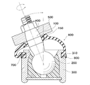
- Patent Document 1 a dust cover for a ball joint as shown in FIG. 4 is known as a ball joint on which a dust cover is attached for the purpose of dustproofing and waterproofing of a ball joint joint portion.
- the ball head 200 formed at one end of the ball stud 100 is held in the socket 300.
- the shaft 400 at the other end of the ball stud 100 is tightened and fixed to the knuckle 500.
- the other end of the large diameter opening 800 of the dust cover 600 made of rubbery elastic material is fitted and held by the holding ring 700 in the step 310 formed on the outer peripheral surface of the socket 300 and the reinforcing ring is embedded.
- the small diameter opening 150 is held by the shaft 400.
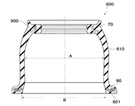
- the film portion of the dust cover 600 of this type has a drum-like shape, it is impossible to integrally embed the reinforcing ring in the large diameter opening 800 at one end because of the restriction on molding. For this reason, there was a problem in assemblability. Therefore, when the reinforcing ring is integrally embedded in the large diameter opening 800 at one end, the shape of the film portion of the dust cover 600 has to be made cylindrical as shown in FIG. That is, the maximum inner diameter A of the film portion 610 of the rubber-like elastic material dust cover 600 is designed to be smaller than the inner diameter B of the reinforcing ring 801 embedded in the large diameter opening 800 at one end. With such a shape, the middle mold of the mold can be taken out.
- the present invention has been made in view of such problems, and it is possible to form the film portion into a drum shape even in a mode in which a reinforcing ring is embedded in the large diameter opening at one end and the small diameter opening at the other end of the dust cover. It is an object of the present invention to provide functional superiority and assembly superiority by suppressing distortion applied to the film portion of the dust cover to a low level and suppressing deterioration in durability of the dust cover.
- the ball head formed at one end of the ball stud is held in the socket, the shaft at the other end of the ball stud is clamped and fixed to the knuckle, and one end where the reinforcing ring is embedded
- a membrane in which the large diameter opening is fixedly held on the outer peripheral surface of the socket, and the other end small diameter opening in which the reinforcing ring is embedded is held by the shaft, and the membrane connecting the large diameter opening and the small diameter opening
- the maximum inner diameter of the film portion is larger than the inner diameter of the reinforcing ring embedded in the one end large diameter opening.
- the present invention has the following effects. According to the dust cover for a ball joint of the invention as set forth in claim 1, even if the reinforcing ring is embedded in the large diameter opening at one end and the small diameter opening at the other end of the dust cover, strain applied to the film of the dust cover Can be provided with functional superiority and assembly superiority by suppressing the reduction of the durability of the dust cover and the reduction of the durability of the dust cover. Furthermore, according to the dust cover for a ball joint of the invention as set forth in claim 2, the distortion applied to the film portion of the dust cover is suppressed to a low level by making the film portion shape into a drum shape, and the deterioration of the durability of the dust cover is suppressed. You can do it.
- the core type slightly smaller than the inner diameter of the reinforcing ring, and the plurality of divided crescent-shaped crescent-shaped crescents forming a drum shape
- the dust cover provided with the drum-shaped film portion can be easily formed by forming these parts by using a forming mold which is taken out while sequentially disassembling.
- the ball head 2 formed at one end of the ball stud 1 is held in the socket 3 and the other end of the ball stud 1 is
- the shaft 4 is tightened and fixed to the knuckle 5, one end large diameter opening 8 in which the reinforcing ring 81 is embedded is fixed and held on the outer peripheral surface of the socket 3, and the other end small diameter opening 7 in which the reinforcing ring 9 is embedded is the shaft 4, and has a basic configuration including a film portion 61 connecting the large diameter opening 8 and the small diameter opening 7.
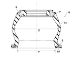
- the maximum inner diameter X of the film portion 61 is larger than the inner diameter Y of the reinforcing ring 81 embedded in the large diameter opening 8 at one end. More specifically, the film portion 61 has a drum shape, and the vicinity of the maximum inner diameter X is the thinnest. For this reason, the distortion added to the film part of a dust cover can be restrained small, and the fall of durability of a dust cover can be suppressed.
- the maximum inner diameter X of the film portion 61 is larger than the inner diameter Y of the reinforcing ring 81 embedded in the large diameter opening 8 at one end, a device is required for molding.
- a specific forming method there are a method of forming with a forming mold provided with a middle and an outer mold, and a method of forming an unvulcanized rubber having a cylindrical shape of the film portion 61 into a drum shape by blow molding.
- the maximum inner diameter X of the film portion 61 is larger than the inner diameter Y of the reinforcing ring 81 embedded in the large diameter opening 8 at one end, It is necessary to be able to take out the middle size from the inside of the molded dust cover. More specifically, the core type slightly smaller than the inner diameter Y of the reinforcing ring 81, and the plurality of divided half-moon shaped half-moon types forming the drum shape, and these types are sequentially disassembled It can be molded by taking it out.
- the dust cover for a ball joint has the following dimensional relationship.
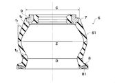
- the maximum outer diameter Z of the hourglass-shaped film portion 61 is larger than the outer diameter C on the other end small diameter opening 7 side of the film portion 61 and the outer diameter D on the one end large diameter opening 8 side of the film 61.
- the thickness t1 of the film portion 61 at the maximum outer diameter Z portion is greater than the thickness t2 at the other end small diameter opening 7 side of the film portion 61 and the thickness t3 at the one end large diameter opening 8 side of the film 61 It is molded thin.
- a metal material or a resin material is used as the reinforcing ring 9 and the reinforcing ring 81, and the reinforcing ring 81 is made of a steel plate such as SPCC manufactured by punching.
- the material of the dust cover 6 is appropriately selected from rubber-like elastic materials such as chloroprene, thermoplastic elastomers such as polyester elastomer, thermoplastic polyurethane, etc. in accordance with applications and used.
- It can be used for a ball joint used for a suspension system and a steering system of a car.
Landscapes
- Engineering & Computer Science (AREA)
- General Engineering & Computer Science (AREA)
- Mechanical Engineering (AREA)
- Pivots And Pivotal Connections (AREA)
- Diaphragms And Bellows (AREA)
- Sealing Devices (AREA)
- Moulds For Moulding Plastics Or The Like (AREA)
Abstract
ダストカバーの一端大径開口部及び他端小径開口部に補強環を埋設した態様であっても、膜部形状を鼓形状とする事により、ダストカバーの膜部に加わる歪みを少なく抑え、ダストカバーの耐久性の低下を抑止することにより、機能的優位性と組み付け優位性を備えることが出来る。 このため、ボールスタッドの一端に形成された球頭部がソケット内に保持され、前記ボールスタッドの他端の軸はナックルに締め付け固定され、補強環が埋設された一端大径開口部が前記ソケットの外周面に固定保持され、補強環が埋設された他端小径開口部が前記軸に保持され、前記大径開口部と前記小径開口部とを連結している膜部を備えた弾性材製ボールジョイント用ダストカバーにおいて、前記膜部の最大内径が前記一端大径開口部に埋設された前記補強環の内径よりも大きい構成とした。
Description
本発明は、ボールジョイント用ダストカバーに関する。
また、本発明は、自動車懸架装置、操舵装置等に使用されるボールジョイント用ダストカバーに関する。
また、本発明は、自動車懸架装置、操舵装置等に使用されるボールジョイント用ダストカバーに関する。
従来、ボールジョイント継ぎ手部の防塵、防水を目的としてダストカバーが装着されているボールジョイントとしては図4に記載のボールジョイント用ダストカバーが知られている。(特許文献1)
この種ボールジョイント用ダストカバーのシール構造は、ボールスタッド100の一端に形成された球頭部200がソケット300内に保持されている。
そして、ボールスタッド100の他端の軸400は、ナックル500に締め付け固定されている。
一方、ゴム状弾性材製ダストカバー600の一端大径開口部800が、ソケット300の外周面に形成された段部310に、保持リング700により嵌合保持され、補強環が埋設された他端小径開口部150が軸400に保持された構成となっている。
そして、ボールスタッド100の他端の軸400は、ナックル500に締め付け固定されている。
一方、ゴム状弾性材製ダストカバー600の一端大径開口部800が、ソケット300の外周面に形成された段部310に、保持リング700により嵌合保持され、補強環が埋設された他端小径開口部150が軸400に保持された構成となっている。
この種、従来のダストカバー600の膜部は、鼓形状を呈している為、成形上の制約から、一端大径開口部800に補強環を一体的に埋設することは出来なかった。
この為、組み付け性に問題が有った。
そこで、一端大径開口部800に補強環を一体的に埋設する場合、ダストカバー600の膜部の形状を鼓形状から、図5に示す様な円筒形状にせざるを得なかった。
すなわち、ゴム状弾性材製ダストカバー600の膜部610の最大内径Aは、一端大径開口部800に埋設した補強環801の内径Bよりも小さく設計されている。
この様な形状とする事により、成形型の中型を取り出すことが出来る。
この為、組み付け性に問題が有った。
そこで、一端大径開口部800に補強環を一体的に埋設する場合、ダストカバー600の膜部の形状を鼓形状から、図5に示す様な円筒形状にせざるを得なかった。
すなわち、ゴム状弾性材製ダストカバー600の膜部610の最大内径Aは、一端大径開口部800に埋設した補強環801の内径Bよりも小さく設計されている。
この様な形状とする事により、成形型の中型を取り出すことが出来る。
しかし、組み付け性は良いが、ダストカバー600の形状が、円筒形状に近付くにつれ、ダストカバー600の膜部610に加わる歪みが大きくなる傾向が有る。
この結果、ダストカバー600の膜部610に亀裂や破損が発生し、耐久性が低下する問題を惹起した。
更に、ダストカバー600のセット時にダストカバー600の膜部610の円周上の一部が内径側に異常変形する問題を招来した。
この結果、ダストカバー600の膜部610に亀裂や破損が発生し、耐久性が低下する問題を惹起した。
更に、ダストカバー600のセット時にダストカバー600の膜部610の円周上の一部が内径側に異常変形する問題を招来した。
本発明は、このような課題に鑑みてなされたものであり、ダストカバーの一端大径開口部及び他端小径開口部に補強環を埋設した態様であっても、膜部形状を鼓形状とする事により、ダストカバーの膜部に加わる歪みを少なく抑え、ダストカバーの耐久性の低下を抑止することにより、機能的優位性と組み付け優位性を備えることを目的とする。
本発明のボールジョイント用ダストカバーは、ボールスタッドの一端に形成された球頭部がソケット内に保持され、前記ボールスタッドの他端の軸はナックルに締め付け固定され、補強環が埋設された一端大径開口部が前記ソケットの外周面に固定保持され、補強環が埋設された他端小径開口部が前記軸に保持され、前記大径開口部と前記小径開口部とを連結している膜部を備えた弾性材製ボールジョイント用ダストカバーにおいて、前記膜部の最大内径が前記一端大径開口部に埋設された前記補強環の内径よりも大きいことを特徴とする。
本発明は、以下に記載されるような効果を奏する。
請求項1記載の発明のボールジョイント用ダストカバーによれば、ダストカバーの一端大径開口部及び他端小径開口部に補強環を埋設した態様であっても、ダストカバーの膜部に加わる歪みを少なく抑え、ダストカバーの耐久性の低下を抑止することにより、機能的優位性と組み付け優位性を備えることが出来る。
更に、請求項2記載の発明のボールジョイント用ダストカバーによれば、膜部形状を鼓形状とする事により、ダストカバーの膜部に加わる歪みを少なく抑え、ダストカバーの耐久性の低下を抑止することが出来る。
請求項1記載の発明のボールジョイント用ダストカバーによれば、ダストカバーの一端大径開口部及び他端小径開口部に補強環を埋設した態様であっても、ダストカバーの膜部に加わる歪みを少なく抑え、ダストカバーの耐久性の低下を抑止することにより、機能的優位性と組み付け優位性を備えることが出来る。
更に、請求項2記載の発明のボールジョイント用ダストカバーによれば、膜部形状を鼓形状とする事により、ダストカバーの膜部に加わる歪みを少なく抑え、ダストカバーの耐久性の低下を抑止することが出来る。
更に、請求項3記載の発明のボールジョイント用ダストカバーによれば、補強環の内径よりも僅かに小さい芯型と、鼓形状を形成する複数個に分割された断面半月状の半月型により構成し、これらの型を順次分解しながら取り出す成形金型により成形する事により、鼓形状の膜部を備えたダストカバーを容易に成形する事が出来る。
以下、本発明を実施するための形態について説明する。
図1及び図2に示される様に、本発明に係るボールジョイント用ダストカバーは、ボールスタッド1の一端に形成された球頭部2がソケット3内に保持され、このボールスタッド1の他端の軸4はナックル5に締め付け固定され、補強環81が埋設された一端大径開口部8がソケット3の外周面に固定保持され、補強環9が埋設された他端小径開口部7が軸4に保持され、大径開口部8と小径開口部7とを連結している膜部61を備えた基本的構成を備えている。
図1及び図2に示される様に、本発明に係るボールジョイント用ダストカバーは、ボールスタッド1の一端に形成された球頭部2がソケット3内に保持され、このボールスタッド1の他端の軸4はナックル5に締め付け固定され、補強環81が埋設された一端大径開口部8がソケット3の外周面に固定保持され、補強環9が埋設された他端小径開口部7が軸4に保持され、大径開口部8と小径開口部7とを連結している膜部61を備えた基本的構成を備えている。
そして、この膜部61の最大内径Xが一端大径開口部8に埋設された補強環81の内径Yよりも大きい形状となっている。
より具体的には、膜部61が鼓形状であって、最大内径Xの近傍が最も薄肉となっている。
この為、ダストカバーの膜部に加わる歪みを少なく抑え、ダストカバーの耐久性の低下を抑止することが出来る。
より具体的には、膜部61が鼓形状であって、最大内径Xの近傍が最も薄肉となっている。
この為、ダストカバーの膜部に加わる歪みを少なく抑え、ダストカバーの耐久性の低下を抑止することが出来る。
また、膜部61の最大内径Xが一端大径開口部8に埋設された補強環81の内径Yよりも大きい形状となっている為、成形には工夫が求められる。
具体的成形方法としては、中型及び外型を備えた成形金型により成形する方法と、膜部61の形状が円筒状の未加硫ゴムをブロー成形により鼓形状とする方法である。
しかし、成形金型により成形する場合、膜部61の最大内径Xが一端大径開口部8に埋設された補強環81の内径Yよりも大きい形状となっている為、中型を分割型として、成形されたダストカバー内部から中型を取り出せる工夫が必要である。
より具体的には、補強環81の内径Yよりも僅かに小さい芯型と、鼓形状を形成する複数個に分割された断面半月状の半月型により構成し、これらの型を順次分解しながら取り出す事により成形可能となる。
より具体的には、補強環81の内径Yよりも僅かに小さい芯型と、鼓形状を形成する複数個に分割された断面半月状の半月型により構成し、これらの型を順次分解しながら取り出す事により成形可能となる。
特に、成形金型により成形する事により、寸法精度が良好で、ゴム物性も低下する事のないダストカバーを得る事が出来る。
図3に示す様に、本発明に係るボールジョイント用ダストカバーは、以下に述べる様な寸法関係になっている。
鼓形状の膜部61の最大外径Zは、膜部61の他端小径開口部7側の外径C及び膜部61の一端大径開口部8側の外径Dよりも大きい。
また、膜部61の最大外径Z部の肉厚t1は、膜部61の他端小径開口部7側の肉厚t2及び膜部61の一端大径開口部8側の肉厚t3よりも薄く成形されている。
この様な形状とする事により、ダストカバー6の膜部61に加わる歪みを少なく抑え、ダストカバー6の耐久性の低下を抑止することが出来る。
鼓形状の膜部61の最大外径Zは、膜部61の他端小径開口部7側の外径C及び膜部61の一端大径開口部8側の外径Dよりも大きい。
また、膜部61の最大外径Z部の肉厚t1は、膜部61の他端小径開口部7側の肉厚t2及び膜部61の一端大径開口部8側の肉厚t3よりも薄く成形されている。
この様な形状とする事により、ダストカバー6の膜部61に加わる歪みを少なく抑え、ダストカバー6の耐久性の低下を抑止することが出来る。
また、ダストカバー6内には、グリースが封入されている。
補強環9及び補強環81は、金属材若しくは樹脂材が使用されるが、補強環81は、SPCC等の鋼板から打ち抜き加工により製作されたものを使用している。
また、ダストカバー6の材質は、クロロプレン等のゴム状弾性材や、ポリエステル系エラストマー、熱可塑性ポリウレタン等の熱可塑性エラストマーから、適宜用途に合わせ選択して使用される。
また、本発明は上述の発明を実施するための最良の形態に限らず本発明の要旨を逸脱することなくその他種々の構成を採り得ることはもちろんである。
自動車の懸架装置及び操舵装置等に使用されるボールジョイントに使用できる。
1 ボールスタッド
2 球頭部
3 ソケット
4 軸
5 ナックル
6 ダストカバー
7 小径開口部
8 大径開口部
9 補強環
61 膜部
81 補強環
2 球頭部
3 ソケット
4 軸
5 ナックル
6 ダストカバー
7 小径開口部
8 大径開口部
9 補強環
61 膜部
81 補強環
Claims (3)
- ボールスタッド(1)の一端に形成された球頭部(2)がソケット(3)内に保持され、前記ボールスタッド(1)の他端の軸(4)はナックル(5)に締め付け固定され、補強環(81)が埋設された一端大径開口部(8)が前記ソケット(3)の外周面に固定保持され、補強環(9)が埋設された他端小径開口部(7)が前記軸(4)に保持され、前記大径開口部(8)と前記小径開口部(7)とを連結している膜部(61)を備えた弾性材製ボールジョイント用ダストカバー(6)において、
前記膜部(61)の最大内径(X)が前記一端大径開口部(8)に埋設された前記補強環(81)の内径(Y)よりも大きいことを特徴とするボールジョイント用ダストカバー。 - 前記膜部(61)が鼓形状であって、前記最大内径(X)部が最も薄肉となっていることを特徴とする請求項1記載のボールジョイント用ダストカバー。
- 補強環(81)の内径(Y)よりも僅かに小さい芯型と、鼓形状を形成する複数個に分割された断面半月状の半月型により構成し、これらの型を順次分解しながら取り出す成形金型により成形したことを特徴とする請求項1または2記載のボールジョイント用ダストカバー。
Priority Applications (3)
| Application Number | Priority Date | Filing Date | Title |
|---|---|---|---|
| CN201480030077.1A CN105308337A (zh) | 2013-05-28 | 2014-05-15 | 球窝接头用防尘罩 |
| EP14804001.7A EP3006749B1 (en) | 2013-05-28 | 2014-05-15 | Ball joint dust cover |
| US14/782,747 US20160053804A1 (en) | 2013-05-28 | 2014-05-15 | Dust cover for ball joint |
Applications Claiming Priority (2)
| Application Number | Priority Date | Filing Date | Title |
|---|---|---|---|
| JP2013-111528 | 2013-05-28 | ||
| JP2013111528A JP6176588B2 (ja) | 2013-05-28 | 2013-05-28 | ボールジョイント用ダストカバー |
Publications (1)
| Publication Number | Publication Date |
|---|---|
| WO2014192548A1 true WO2014192548A1 (ja) | 2014-12-04 |
Family
ID=51988583
Family Applications (1)
| Application Number | Title | Priority Date | Filing Date |
|---|---|---|---|
| PCT/JP2014/062903 Ceased WO2014192548A1 (ja) | 2013-05-28 | 2014-05-15 | ボールジョイント用ダストカバー |
Country Status (5)
| Country | Link |
|---|---|
| US (1) | US20160053804A1 (ja) |
| EP (1) | EP3006749B1 (ja) |
| JP (1) | JP6176588B2 (ja) |
| CN (1) | CN105308337A (ja) |
| WO (1) | WO2014192548A1 (ja) |
Families Citing this family (4)
| Publication number | Priority date | Publication date | Assignee | Title |
|---|---|---|---|---|
| CN109488767A (zh) * | 2018-07-13 | 2019-03-19 | 中国航空工业集团公司济南特种结构研究所 | 一种降低雷达罩根部装配应力的密封结构 |
| JPWO2021215363A1 (ja) * | 2020-04-22 | 2021-10-28 | ||
| CN112326666A (zh) * | 2020-10-16 | 2021-02-05 | 洛阳轴承研究所有限公司 | 一种轴承套圈外观检测辅助装置 |
| US11713783B2 (en) * | 2021-07-23 | 2023-08-01 | Federal-Mogul Motorparts Llc | Grease boot for a ball joint |
Citations (9)
| Publication number | Priority date | Publication date | Assignee | Title |
|---|---|---|---|---|
| JPS58165366U (ja) * | 1982-04-30 | 1983-11-04 | 日産自動車株式会社 | 被覆体 |
| JPS62137408A (ja) | 1985-12-11 | 1987-06-20 | Musashi Seimitsu Ind Co Ltd | ボ−ルジヨイント用ダストカバ− |
| JPH0665614U (ja) * | 1993-02-19 | 1994-09-16 | 株式会社リズム | ボールジョイント等のダストカバー |
| JP2001323923A (ja) * | 2000-05-12 | 2001-11-22 | Musashi Seimitsu Ind Co Ltd | ボールジョイント |
| JP2009030793A (ja) * | 2007-02-27 | 2009-02-12 | Nok Corp | ダストカバーの固定構造 |
| JP2010501791A (ja) * | 2006-08-25 | 2010-01-21 | ツェットエフ フリードリヒスハーフェン アクチエンゲゼルシャフト | シールベローズまたは襞付きベローズ |
| JP2011179549A (ja) * | 2010-02-26 | 2011-09-15 | Somic Ishikawa Inc | シール部材及びボールジョイント |
| JP2012126033A (ja) * | 2010-12-16 | 2012-07-05 | Toyoda Gosei Co Ltd | Cvjブーツ成形用金型及びcvjブーツ成形方法 |
| JP2012229734A (ja) * | 2011-04-26 | 2012-11-22 | Nok Corp | ボールジョイント用ダストカバー |
Family Cites Families (5)
| Publication number | Priority date | Publication date | Assignee | Title |
|---|---|---|---|---|
| JPS523068B2 (ja) * | 1973-09-25 | 1977-01-26 | ||
| JPS63194914A (ja) * | 1987-02-10 | 1988-08-12 | Masaharu Kaneko | 深物の成型金型 |
| JPH08159147A (ja) * | 1994-12-08 | 1996-06-18 | Somic Ishikawa:Kk | ロッドエンド軸受装置 |
| EP1630431B1 (en) * | 2003-04-07 | 2009-11-11 | Kabushiki Kaisha Somic Ishikawa | Ball joint |
| CN2921424Y (zh) * | 2006-05-19 | 2007-07-11 | 上海采埃孚伦福德底盘技术有限公司 | 车用球关节结构 |
-
2013
- 2013-05-28 JP JP2013111528A patent/JP6176588B2/ja active Active
-
2014
- 2014-05-15 WO PCT/JP2014/062903 patent/WO2014192548A1/ja not_active Ceased
- 2014-05-15 EP EP14804001.7A patent/EP3006749B1/en not_active Not-in-force
- 2014-05-15 US US14/782,747 patent/US20160053804A1/en not_active Abandoned
- 2014-05-15 CN CN201480030077.1A patent/CN105308337A/zh active Pending
Patent Citations (9)
| Publication number | Priority date | Publication date | Assignee | Title |
|---|---|---|---|---|
| JPS58165366U (ja) * | 1982-04-30 | 1983-11-04 | 日産自動車株式会社 | 被覆体 |
| JPS62137408A (ja) | 1985-12-11 | 1987-06-20 | Musashi Seimitsu Ind Co Ltd | ボ−ルジヨイント用ダストカバ− |
| JPH0665614U (ja) * | 1993-02-19 | 1994-09-16 | 株式会社リズム | ボールジョイント等のダストカバー |
| JP2001323923A (ja) * | 2000-05-12 | 2001-11-22 | Musashi Seimitsu Ind Co Ltd | ボールジョイント |
| JP2010501791A (ja) * | 2006-08-25 | 2010-01-21 | ツェットエフ フリードリヒスハーフェン アクチエンゲゼルシャフト | シールベローズまたは襞付きベローズ |
| JP2009030793A (ja) * | 2007-02-27 | 2009-02-12 | Nok Corp | ダストカバーの固定構造 |
| JP2011179549A (ja) * | 2010-02-26 | 2011-09-15 | Somic Ishikawa Inc | シール部材及びボールジョイント |
| JP2012126033A (ja) * | 2010-12-16 | 2012-07-05 | Toyoda Gosei Co Ltd | Cvjブーツ成形用金型及びcvjブーツ成形方法 |
| JP2012229734A (ja) * | 2011-04-26 | 2012-11-22 | Nok Corp | ボールジョイント用ダストカバー |
Non-Patent Citations (1)
| Title |
|---|
| See also references of EP3006749A4 |
Also Published As
| Publication number | Publication date |
|---|---|
| JP2014231847A (ja) | 2014-12-11 |
| EP3006749B1 (en) | 2020-09-30 |
| JP6176588B2 (ja) | 2017-08-09 |
| EP3006749A1 (en) | 2016-04-13 |
| EP3006749A4 (en) | 2016-06-08 |
| CN105308337A (zh) | 2016-02-03 |
| US20160053804A1 (en) | 2016-02-25 |
Similar Documents
| Publication | Publication Date | Title |
|---|---|---|
| JP5888577B1 (ja) | ボールジョイント用ダストカバー | |
| JP6025024B2 (ja) | ボールジョイント用ダストカバー | |
| US20100133758A1 (en) | Sealing device | |
| WO2014192548A1 (ja) | ボールジョイント用ダストカバー | |
| JP5900790B2 (ja) | ボールジョイント用ダストカバー | |
| JP6872316B2 (ja) | プロペラシャフト用ダイナミックダンパ | |
| CN108167376A (zh) | 动力减振器 | |
| WO2017154672A1 (ja) | ダストカバー及び密封構造 | |
| WO2014057779A1 (ja) | ボールジョイント用ダストカバー | |
| JP6359361B2 (ja) | ブッシュ | |
| JP6899299B2 (ja) | ダストカバー | |
| JP2013160326A (ja) | ボールジョイント用ダストカバー | |
| JP2012042041A (ja) | 防振ゴムの製造方法 | |
| JP5936064B2 (ja) | ボールジョイント用ダストカバー | |
| JP4753670B2 (ja) | ブッシュ | |
| JP2014152855A (ja) | ボールジョイント用ダストカバー | |
| JP6241209B2 (ja) | ダストブーツ及びその製造方法 | |
| JP2015086901A (ja) | ボールジョイント用ダストカバー | |
| JP2009002394A (ja) | ラバーブッシュ | |
| JP2016109174A (ja) | ダストカバー | |
| JP6383197B2 (ja) | センターベアリングサポートの取付構造 | |
| WO2018097119A1 (ja) | ダストシール | |
| JP2006214575A (ja) | ジョイントブーツ | |
| JP2016130559A (ja) | ダストカバー | |
| JP2007092872A (ja) | 等速ジョイント用ブーツ |
Legal Events
| Date | Code | Title | Description |
|---|---|---|---|
| WWE | Wipo information: entry into national phase |
Ref document number: 201480030077.1 Country of ref document: CN |
|
| 121 | Ep: the epo has been informed by wipo that ep was designated in this application |
Ref document number: 14804001 Country of ref document: EP Kind code of ref document: A1 |
|
| WWE | Wipo information: entry into national phase |
Ref document number: 14782747 Country of ref document: US |
|
| WWE | Wipo information: entry into national phase |
Ref document number: 2014804001 Country of ref document: EP |
|
| NENP | Non-entry into the national phase |
Ref country code: DE |