WO2014192562A1 - Procédé de production d'hydrogène et système de production d'hydrogène - Google Patents
Procédé de production d'hydrogène et système de production d'hydrogène Download PDFInfo
- Publication number
- WO2014192562A1 WO2014192562A1 PCT/JP2014/063103 JP2014063103W WO2014192562A1 WO 2014192562 A1 WO2014192562 A1 WO 2014192562A1 JP 2014063103 W JP2014063103 W JP 2014063103W WO 2014192562 A1 WO2014192562 A1 WO 2014192562A1
- Authority
- WO
- WIPO (PCT)
- Prior art keywords
- hydrogen
- liquid
- separation membrane
- gas
- organic compound
- Prior art date
- Legal status (The legal status is an assumption and is not a legal conclusion. Google has not performed a legal analysis and makes no representation as to the accuracy of the status listed.)
- Ceased
Links
Images

Classifications
-
- C—CHEMISTRY; METALLURGY
- C01—INORGANIC CHEMISTRY
- C01B—NON-METALLIC ELEMENTS; COMPOUNDS THEREOF; METALLOIDS OR COMPOUNDS THEREOF NOT COVERED BY SUBCLASS C01C
- C01B3/00—Hydrogen; Gaseous mixtures containing hydrogen; Separation of hydrogen from mixtures containing it; Purification of hydrogen; Reversible storage of hydrogen
- C01B3/02—Production of hydrogen; Production of gaseous mixtures containing hydrogen
- C01B3/22—Production of hydrogen; Production of gaseous mixtures containing hydrogen by decomposition of gaseous or liquid organic compounds
- C01B3/24—Production of hydrogen; Production of gaseous mixtures containing hydrogen by decomposition of gaseous or liquid organic compounds of hydrocarbons
- C01B3/26—Production of hydrogen; Production of gaseous mixtures containing hydrogen by decomposition of gaseous or liquid organic compounds of hydrocarbons using catalysts
-
- B—PERFORMING OPERATIONS; TRANSPORTING
- B01—PHYSICAL OR CHEMICAL PROCESSES OR APPARATUS IN GENERAL
- B01D—SEPARATION
- B01D19/00—Degasification of liquids
- B01D19/0031—Degasification of liquids by filtration
-
- C—CHEMISTRY; METALLURGY
- C01—INORGANIC CHEMISTRY
- C01B—NON-METALLIC ELEMENTS; COMPOUNDS THEREOF; METALLOIDS OR COMPOUNDS THEREOF NOT COVERED BY SUBCLASS C01C
- C01B2203/00—Integrated processes for the production of hydrogen or synthesis gas
- C01B2203/02—Processes for making hydrogen or synthesis gas
- C01B2203/0266—Processes for making hydrogen or synthesis gas containing a decomposition step
- C01B2203/0277—Processes for making hydrogen or synthesis gas containing a decomposition step containing a catalytic decomposition step
-
- C—CHEMISTRY; METALLURGY
- C01—INORGANIC CHEMISTRY
- C01B—NON-METALLIC ELEMENTS; COMPOUNDS THEREOF; METALLOIDS OR COMPOUNDS THEREOF NOT COVERED BY SUBCLASS C01C
- C01B2203/00—Integrated processes for the production of hydrogen or synthesis gas
- C01B2203/04—Integrated processes for the production of hydrogen or synthesis gas containing a purification step for the hydrogen or the synthesis gas
- C01B2203/0405—Purification by membrane separation
-
- C—CHEMISTRY; METALLURGY
- C01—INORGANIC CHEMISTRY
- C01B—NON-METALLIC ELEMENTS; COMPOUNDS THEREOF; METALLOIDS OR COMPOUNDS THEREOF NOT COVERED BY SUBCLASS C01C
- C01B2203/00—Integrated processes for the production of hydrogen or synthesis gas
- C01B2203/04—Integrated processes for the production of hydrogen or synthesis gas containing a purification step for the hydrogen or the synthesis gas
- C01B2203/0405—Purification by membrane separation
- C01B2203/041—In-situ membrane purification during hydrogen production
-
- C—CHEMISTRY; METALLURGY
- C01—INORGANIC CHEMISTRY
- C01B—NON-METALLIC ELEMENTS; COMPOUNDS THEREOF; METALLOIDS OR COMPOUNDS THEREOF NOT COVERED BY SUBCLASS C01C
- C01B2203/00—Integrated processes for the production of hydrogen or synthesis gas
- C01B2203/10—Catalysts for performing the hydrogen forming reactions
- C01B2203/1041—Composition of the catalyst
-
- C—CHEMISTRY; METALLURGY
- C01—INORGANIC CHEMISTRY
- C01B—NON-METALLIC ELEMENTS; COMPOUNDS THEREOF; METALLOIDS OR COMPOUNDS THEREOF NOT COVERED BY SUBCLASS C01C
- C01B2203/00—Integrated processes for the production of hydrogen or synthesis gas
- C01B2203/10—Catalysts for performing the hydrogen forming reactions
- C01B2203/1041—Composition of the catalyst
- C01B2203/1082—Composition of support materials
-
- C—CHEMISTRY; METALLURGY
- C01—INORGANIC CHEMISTRY
- C01B—NON-METALLIC ELEMENTS; COMPOUNDS THEREOF; METALLOIDS OR COMPOUNDS THEREOF NOT COVERED BY SUBCLASS C01C
- C01B2203/00—Integrated processes for the production of hydrogen or synthesis gas
- C01B2203/14—Details of the flowsheet
- C01B2203/148—Details of the flowsheet involving a recycle stream to the feed of the process for making hydrogen or synthesis gas
-
- H—ELECTRICITY
- H01—ELECTRIC ELEMENTS
- H01M—PROCESSES OR MEANS, e.g. BATTERIES, FOR THE DIRECT CONVERSION OF CHEMICAL ENERGY INTO ELECTRICAL ENERGY
- H01M8/00—Fuel cells; Manufacture thereof
- H01M8/06—Combination of fuel cells with means for production of reactants or for treatment of residues
- H01M8/0606—Combination of fuel cells with means for production of reactants or for treatment of residues with means for production of gaseous reactants
- H01M8/0612—Combination of fuel cells with means for production of reactants or for treatment of residues with means for production of gaseous reactants from carbon-containing material
-
- Y—GENERAL TAGGING OF NEW TECHNOLOGICAL DEVELOPMENTS; GENERAL TAGGING OF CROSS-SECTIONAL TECHNOLOGIES SPANNING OVER SEVERAL SECTIONS OF THE IPC; TECHNICAL SUBJECTS COVERED BY FORMER USPC CROSS-REFERENCE ART COLLECTIONS [XRACs] AND DIGESTS
- Y02—TECHNOLOGIES OR APPLICATIONS FOR MITIGATION OR ADAPTATION AGAINST CLIMATE CHANGE
- Y02E—REDUCTION OF GREENHOUSE GAS [GHG] EMISSIONS, RELATED TO ENERGY GENERATION, TRANSMISSION OR DISTRIBUTION
- Y02E60/00—Enabling technologies; Technologies with a potential or indirect contribution to GHG emissions mitigation
- Y02E60/30—Hydrogen technology
- Y02E60/50—Fuel cells
Definitions
- the present invention relates to a hydrogen production method and a hydrogen production system.
- methylcyclohexane is generated by hydrogenation of toluene in a hydrogen production facility (solar power plant, etc.). Methylcyclohexane is transported to or stored in the hydrogen consumption area. In the consumption area, hydrogen and toluene are generated by dehydrogenation of methylcyclohexane. This hydrogen is supplied to the fuel cell. Toluene may be reused as methylcyclohexane by hydrogenation in a hydrogen production facility.
- the organic hydride is an organic compound that can reversibly repeat the release and occlusion of hydrogen by a dehydrogenation reaction and a hydrogenation reaction.
- Organic hydride is a liquid at normal temperature and pressure, and has a volume smaller than that of hydrogen gas, and is less reactive and safer than hydrogen gas. Therefore, organic hydride is more suitable for transportation and storage than hydrogen gas alone.
- Non-Patent Document 1 As a dehydrogenation catalyst for organic hydride, a catalyst in which a platinum-rhenium bimetal is supported on an alumina carrier is known (see Non-Patent Document 1 below).
- the hydrogen recovery rate is the ratio (unit: mol%, etc.) of hydrogen recovered from the total amount of hydrogen generated by dehydrogenation of organic hydride.
- the present invention has been made in view of the above-described problems of the prior art, and an object thereof is to provide a hydrogen production method and a hydrogen production system capable of improving the hydrogen recovery rate.
- the method for producing hydrogen according to one aspect of the present invention includes a first step of generating hydrogen and an organic compound by dehydrogenation of an organic hydride, and a second step of separating hydrogen dissolved in the liquid of the organic compound from the liquid. .
- hydrogen in the second step, hydrogen may be separated from the liquid by a separation membrane that selectively permeates hydrogen out of the liquid and hydrogen dissolved in the liquid. .
- hydrogen generated in the first step and hydrogen separated from the liquid in the second step may be used as fuel for the fuel cell.
- the hydrogen permeability coefficient in the separation membrane is 4.0 ⁇ 10 ⁇ 9 [mol ⁇ m / (m 2 ⁇ s ⁇ Pa)] or more at 30 ° C. Good.
- the separation membrane may be insoluble in the liquid.
- a hydrogen production system includes a dehydrogenation reactor that generates hydrogen and an organic compound by dehydrogenation of an organic hydride, and a gas-liquid separation that separates hydrogen dissolved in the liquid of the organic compound from the liquid.
- a vessel A vessel.
- the gas-liquid separator may include a separation membrane that selectively permeates hydrogen among the liquid and hydrogen dissolved in the liquid.
- the hydrogen production system may be for producing hydrogen used as a fuel for a fuel cell.
- the hydrogen permeability coefficient in the separation membrane is 4.0 ⁇ 10 ⁇ 9 [mol ⁇ m / (m 2 ⁇ s ⁇ Pa)] or more at 30 ° C. Good.
- the separation membrane may be insoluble in the liquid.
- a hydrogen production method and a hydrogen production system capable of improving the hydrogen recovery rate are provided.
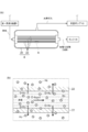
- FIG. 1 is a schematic view showing an embodiment of a hydrogen production method (hydrogen production system) according to the present invention.
- 2a and 2b are schematic views showing a second step provided in an embodiment of the method for producing hydrogen according to the present invention.
- the method for producing hydrogen according to the present embodiment includes a first step of generating hydrogen by dehydrogenation of an organic hydride, and separating hydrogen (hydrogen gas) dissolved in a liquid of an organic compound generated by dehydrogenation from the liquid. And a second step.
- the organic hydride may be, for example, one or more selected from the group consisting of cyclohexane, methylcyclohexane, dimethylcyclohexane, decalin, 1-methyldecalin, 2-methyldecalin and 2-ethyldecalin.
- the “organic compound formed by dehydrogenation” is a dehydrogenated product of an organic hydride (aromatic hydrocarbon, unsaturated cyclic hydrocarbon, etc.), and is at ordinary temperature (about 15 ° C.). It is liquid.
- the dehydration product of organic hydride may be at least one selected from the group consisting of benzene, toluene, xylene, ethylbenzene, tetralin, naphthalene, methylnaphthalene and ethylnaphthalene.
- the organic hydride is methylcyclohexane
- the “organic compound produced by dehydrogenation” is toluene.
- hydrogen is produced using the hydrogen production system 100 shown in FIGS. 1, 2a and 2b.
- the hydrogen production system 100 is a hydrogen production system in a hydrogen station for supplying hydrogen gas as fuel to a fuel cell vehicle, for example.
- organic hydride is supplied into the dehydrogenation reactor 2.
- a dehydrogenation catalyst in the dehydrogenation reactor 2.
- the inside of the dehydrogenation reactor is a reducing atmosphere.
- the dehydrogenation reaction occurs, and at least a pair of hydrogen atoms are extracted from the organic hydride, and a hydrogen molecule, an organic compound such as an aromatic hydrocarbon, Produces.
- the dehydrogenation reaction is a gas phase reaction.
- the dehydrogenation catalyst used in the first step may be a catalyst including, for example, a support and an active metal supported on the support.
- the support may be, for example, one or more selected from the group consisting of alumina (Al 2 O 3 ), silica (SiO 2 ), titania (TiO 2 ), and carbon (activated carbon).
- the alumina may be ⁇ -alumina, ⁇ -alumina, ⁇ -alumina, ⁇ -alumina or alumite.
- the active metal is selected from the group consisting of platinum (Pt), rhodium (Rh), palladium (Pd), nickel (Ni), ruthenium (Ru), iridium (Ir), osmium (Os) and rhenium (Re), for example. It may be one kind or plural kinds.
- the dehydrogenation catalyst may be, for example, a catalyst comprising ⁇ -alumina, platinum supported on ⁇ -alumina, and a Group 3 metal.
- This dehydrogenation catalyst is particularly excellent in dehydrogenation activity and hardly deactivates over time due to the dehydrogenation reaction.
- the Group 3 metal may be one or more selected from scandium (Sc), yttrium (Y), lanthanoid and actinoid.
- the lanthanoid can be, for example, lanthanum (La) or cerium (Ce). Of these Group 3 metals, cerium is relatively preferred.
- the dehydrogenation catalyst can have a remarkably high dehydrogenation activity by containing cerium.
- the product (hydrogen molecule and organic compound) of the dehydrogenation reaction is supplied from the dehydrogenation reactor 2 into the first gas-liquid separator 4.
- the temperature in the first gas-liquid separator 4 is not less than the melting point of the organic compound and less than the boiling point of the organic compound, and may be room temperature (about 15 ° C.).
- the temperature in the first gas-liquid separator 4 may be about ⁇ 94.97 to 110.63 ° C. or 15 ° C.
- the pressure in the 1st gas-liquid separator 4 is a normal pressure (substantially atmospheric pressure). Therefore, the hydrogen molecules in the first gas-liquid separator 4 are gases, and the organic compounds in the first gas-liquid separator 4 are liquids.
- the product of the dehydrogenation reaction is separated into hydrogen gas (gas phase, gas layer) and organic compound liquid (liquid phase, liquid layer).
- a small amount of vapor of an organic compound is mixed in the gas phase.
- the partial pressure of the organic compound in the gas phase is at most about the saturated vapor pressure of the organic compound.
- a part of hydrogen (a trace amount of hydrogen molecules) generated by dehydrogenation is dissolved in the liquid phase.
- organic hydride that has not been dehydrogenated may remain in the liquid phase.
- the gas phase (hydrogen gas) in the first gas-liquid separator 4 is supplied to the hydrogen purifier 6.
- the liquid phase (organic compound liquid) in the first gas-liquid separator 4 is supplied to the second gas-liquid separator. Below, a 2nd gas-liquid separator is described as the deaeration apparatus 8.
- the deaeration device 8 includes a chamber 20 and a plurality of separation membranes 22 arranged in the chamber 20.
- Each separation membrane 22 is a hollow fiber (tube).
- the plurality of separation membranes 22 are bundled.
- FIG. 2B is a cross-sectional view parallel to the longitudinal direction of the separation membrane 22 in a portion b of the separation membrane 22 provided in the deaeration device 8 of FIG. 2A.
- the separation membrane 22 Since the separation membrane 22 has a hollow fiber shape, the surface area per unit volume of the separation membrane 22 is increased as compared with a flat carbon membrane, so that the hydrogen separation ability of the separation membrane 22 is improved. Further, the hollow fiber-shaped separation membrane 22 is excellent in pressure resistance, and is therefore suitable for gas-liquid separation by pressure difference. Furthermore, the hollow fiber-shaped separation membrane 22 is easy to process and has a large surface area per unit volume. Therefore, by using the hollow fiber-shaped separation membrane 22, it is possible to manufacture a deaeration device 8 that is small and excellent in separation performance.
- the inside of the chamber 20 is deaerated and decompressed by the vacuum pump 10.
- the inside of the chamber 20 and the inside of each separation membrane 22 are separated by each separation membrane 22.
- the liquid of the organic compound supplied from the first gas-liquid separator 4 is introduced into the inside of each separation membrane 22 from one end portion of each separation membrane 22.
- Each separation membrane 22 has innumerable pores penetrating the separation membrane 22 in the thickness direction. The pore size is small enough to selectively permeate hydrogen molecules among molecules composed of a plurality of atoms. Therefore, only the hydrogen molecules of the organic compound liquid introduced into the separation membrane 22 and the hydrogen molecules dissolved in the liquid are driven by the pressure difference between the inside of the separation membrane 22 and the inside of the chamber 20. It passes through the separation membrane 22 and moves into the chamber 20.
- Hydrogen molecules (hydrogen gas) moved from the inside of the separation membrane 22 into the chamber 20 are supplied to the low-pressure compressor 12 via the vacuum pump 10 and compressed.
- the hydrogen gas compressed by the low-pressure compressor 12 is further compressed by the high-pressure compressor 14 and then used as fuel for the fuel cell.
- the organic compound liquid inside the separation membrane 22 cannot pass through each separation membrane 22. Therefore, the organic compound liquid in the separation membrane 22 is discharged out of the deaeration device 8 from the other end of each separation membrane 22 after the hydrogen molecules are separated, and is supplied into the tank 16.
- the organic compound in the tank 16 may be reused as an organic hydride by being hydrogenated.
- the organic compound liquid itself is in an atmosphere of normal temperature and normal pressure (substantially atmospheric pressure).
- normal temperature and normal pressure substantially atmospheric pressure
- the separation of hydrogen molecules Liquid degassing
- degas is a method originally intended to remove impurities (gas) from its object (organic compound liquid), and therefore degas selectively collects only a specific gas (hydrogen molecule). Therefore, it is difficult to increase the purity of the gas. Further, if degas using other gas such as nitrogen gas is performed, a process for separating the other gas from the hydrogen gas recovered by degas is further required, which increases the production cost of hydrogen gas. .
- the permeation coefficient of hydrogen molecules in the separation membrane 22 may be 4.0 ⁇ 10 ⁇ 9 to 1.0 ⁇ 10 ⁇ 5 [mol ⁇ m / (m 2 ⁇ s ⁇ Pa)] at 30 ° C.
- the separation membrane 22 may be insoluble in an organic compound liquid. In this case, the separation membrane 22 is hardly deteriorated in the second step, and the selective separation ability of hydrogen molecules in the separation membrane 22 is easily maintained.
- the separation membrane 22 when methylcyclohexane is used as the organic hydride, the separation membrane 22 may be insoluble in toluene produced by dehydrogenation of methylcyclohexane.
- the deterioration of the separation membrane 22 means that the separation membrane 22 is dissolved by the organic compound, the diameter of the pores penetrating the separation membrane 22 is increased, and molecules of the organic compound larger than hydrogen molecules also pass through the separation membrane 22. It means to end up. That is, when the separation membrane is dissolved in the organic compound, the hydrogen separation ability of the separation membrane is reduced.
- the diameter of the pores penetrating the separation membrane 22 in the thickness direction allows permeation of hydrogen molecules having a maximum molecular diameter of 0.289 nm and an organic compound having a molecular diameter larger than that of the hydrogen molecules (for example, the molecular diameter is 0). It is sufficient that the size is such that it does not transmit (toluene of .585 nm). Accordingly, the pore diameter may be, for example, 0.25 to 0.5 nm, 0.25 to 0.3 nm, or 0.3 to 0.5 nm.
- the permeability of each molecule in the separation membrane 22 is the detection limit.
- the upper and lower limit values of the molecular diameter of molecules that are equal to or greater than the value substantially correspond to the upper and lower limit values of the pore diameter of the separation membrane 22.
- the average value of the pore diameter may be, for example, a weighted average value of the molecular diameter of each molecule based on the measured value of the permeability of each molecule, and the integrated value of the number of pores in the pore diameter distribution curve is 50%.
- the pore diameter (d50) may be sufficient.
- the thickness of the separation membrane 22 may be 5 to 100 ⁇ m. Thereby, it becomes easy to achieve both sufficient mechanical strength of the separation membrane 22 and excellent hydrogen separation ability.
- the permeability coefficient of hydrogen molecules at 30 ° C. is 4.0 ⁇ 10 ⁇ 9 [mol ⁇ m / (m 2 ⁇ s ⁇ Pa)] or more, the pore diameter is about 0.5 nm or less, and
- the separation membrane 22 that is insoluble in the liquid may be, for example, a fluororesin membrane, a silica membrane, a zeolite membrane, or a carbon membrane. Since these separation membranes are excellent in hydrogen separation ability and hardly dissolve in organic compounds, the small pore diameter of the separation membrane is maintained, and the separation ability of hydrogen in the separation membrane is unlikely to decrease with time.
- the fluororesin film is made of PTFE (polytetrafluoroethylene), PFA (tetrafluoroethylene / perfluoroalkyl vinyl ether copolymer), FEP (tetrafluoroethylene / hexafluoropropylene copolymer) and ETFE (tetrafluoroethylene / ethylene copolymer). It may be a film composed of at least one or more selected from the group consisting of (polymer). Among these fluororesin films, a film made of PFA is relatively preferable.
- the PFA membrane is particularly excellent in the function of selectively permeating hydrogen dissolved in an organic compound and not permeating the organic compound.
- the zeolite membrane may be a membrane composed of zeolite having an eight-membered ring structure, and a membrane composed of chabazite-type zeolite is relatively preferable.
- the carbon film is not particularly limited.
- a membrane composed of carbon formed by infusibilization (crosslinking by heating) and firing (carbonization) of an organic polymer such as a poly (2,6-dimethyl-1,4-phenylene oxide) derivative is used as the separation membrane 22. May be used as The hollow fiber-shaped separation membrane 22 is manufactured through an extrusion molding process of the above composition or its raw material, or a molding process using a mold.
- the hydrogen gas supplied from the first gas-liquid separator 4 to the hydrogen purification device 6 is purified by the hydrogen purification device 6.
- the hydrogen purification apparatus 6 includes, for example, an outer cylinder (chamber) and a plurality of hollow fiber carbon membranes arranged in the chamber. A plurality of carbon films are bundled. The inside of the chamber and the inside of each carbon film are separated by each carbon film. Hydrogen gas is introduced into the chamber of the hydrogen purifier 6 from the first gas-liquid separator 4. The inside of each carbon film is degassed and depressurized from one end of each carbon film by a vacuum pump. The carbon film has innumerable pores penetrating the carbon film in the thickness direction.
- the pore diameter is small enough to allow only hydrogen molecules to permeate among molecules composed of a plurality of atoms. Accordingly, the hydrogen molecules in the chamber are driven by the pressure difference between the inside of the chamber and the inside of the carbon film, and move from the outside to the inside of the carbon film. The hydrogen gas that has moved from the inside of the chamber to the inside of the carbon film is compressed by the high-pressure compressor 14 and then used as fuel for the fuel cell. On the other hand, organic compounds (including organic hydrides) in the hydrogen gas in the chamber cannot penetrate each carbon film. In the chamber, not only an organic compound but also a trace amount of hydrogen that has not permeated the carbon film may remain as a gas phase (non-permeating gas).
- the gas phase remaining in the chamber may be supplied into the dehydrogenation reactor 2 together with the organic hydride.
- the organic compound existing in the chamber may be recovered into the tank 16.
- the carbon membrane provided in the hydrogen purifier 6 is not particularly limited.
- a hollow fiber-like carbon membrane manufactured by an extrusion process, an infusibilization process (crosslinking by heating), and a firing process (carbonization) of an organic polymer such as a poly (2,6-dimethyl-1,4-phenylene oxide) derivative May be used.
- the hydrogen recovery rate is improved as compared with a conventional hydrogen production method that does not perform the second step.
- Example 1 [First step] 3.6 ml of alumina supporting a platinum (dehydrogenation catalyst layer) was placed in a flow-type dehydrogenation reactor. Methylcyclohexane (molecular diameter: 0.56 nm) and hydrogen gas were supplied into the dehydrogenation reactor and contacted with the dehydrogenation catalyst layer to dehydrogenate methylcyclohexane. In the dehydrogenation reaction, the atmospheric pressure in the dehydrogenation reactor was adjusted to 0.19 MPa. In the dehydrogenation reactor, the temperature at the center of the dehydrogenation catalyst layer was adjusted to 350 ° C. using an external heating device attached to the dehydrogenation reactor.
- the flow rate of methylcyclohexane (gas) brought into contact with the dehydrogenation catalyst was adjusted to 0.18 ml / min.
- the flow rate of hydrogen gas brought into contact with the dehydrogenation catalyst was adjusted to 8.0 ml / min.
- the liquid in the gas-liquid separator was degassed by the following procedure.
- a membrane made of PFA tetrafluoroethylene / perfluoroalkyl vinyl ether copolymer
- the thickness of the separation membrane 22 was 100 ⁇ m.
- the total value of the areas of the plurality of separation membranes 22 included in the deaeration device 8 was 0.5 m 2 .
- the permeability coefficient of hydrogen molecules in the separation membrane 22 was 4.0 ⁇ 10 ⁇ 9 [mol ⁇ m / (m 2 ⁇ s ⁇ Pa)] at 30 ° C.
- the liquid in the gas-liquid separator was introduced into the inside of each separation membrane 22 from one end of each separation membrane 22 provided in the degassing device 8.
- the inside of the chamber 20 included in the degassing device 8 was depressurized by the vacuum pump 10 and the pressure inside the chamber 20 was adjusted to 50 kPa, thereby degassing the liquid inside the separation membrane 22.
- the composition of the gas recovered from the inside of the chamber 20 by the vacuum pump 10 was analyzed by gas chromatography. As a result of analysis, it was confirmed that the gas in the chamber 20 was hydrogen gas. In addition, toluene and methylcyclohexane were not detected in the gas recovered from the inside of the chamber 20.
- the detection limit value of each of toluene and methylcyclohexane by gas chromatography was 1 mol ⁇ ppm.
- the content of hydrogen molecules in the liquid discharged from the separation membrane 22 after deaeration was measured using a dissolved hydrogen meter. Hydrogen molecules were not detected in the liquid after degassing.
- the detection limit value of the hydrogen molecule by a dissolved hydrogen meter was 100 mol ⁇ ppb.
- the hydrogen gas produced by the method for producing hydrogen according to the present invention is applied to, for example, a fuel for a fuel cell.
Landscapes
- Chemical & Material Sciences (AREA)
- Chemical Kinetics & Catalysis (AREA)
- Organic Chemistry (AREA)
- Health & Medical Sciences (AREA)
- General Health & Medical Sciences (AREA)
- Engineering & Computer Science (AREA)
- Combustion & Propulsion (AREA)
- Inorganic Chemistry (AREA)
- Hydrogen, Water And Hydrids (AREA)
- Separation Using Semi-Permeable Membranes (AREA)
- Degasification And Air Bubble Elimination (AREA)
- Fuel Cell (AREA)
Abstract
L'invention concerne un procédé de production d'hydrogène et un système de production d'hydrogène, dans chacun desquels le taux de collecte d'hydrogène peut être amélioré. Le procédé de production d'hydrogène selon un aspect de la présente invention comprend : une première étape de déshydrogénation d'un halogénure organique pour produire de l'hydrogène ; et une seconde étape de séparation de l'hydrogène qui reste dissous dans un composé organique liquide produit par la déshydrogénation susmentionnée du liquide. Un mode de réalisation du système de production d'hydrogène selon la présente invention est équipé de : un réacteur de déshydrogénation (2) pour la déshydrogénation d'un halogénure organique afin de produire de l'hydrogène et un composé organique ; et un séparateur gaz/liquide (un appareil de désaération (8)) pour séparer du liquide l'hydrogène qui reste dissous dans un liquide du composé organique liquide.
Applications Claiming Priority (2)
| Application Number | Priority Date | Filing Date | Title |
|---|---|---|---|
| JP2013113196A JP5945521B2 (ja) | 2013-05-29 | 2013-05-29 | 水素の製造方法及び水素の製造システム |
| JP2013-113196 | 2013-05-29 |
Publications (1)
| Publication Number | Publication Date |
|---|---|
| WO2014192562A1 true WO2014192562A1 (fr) | 2014-12-04 |
Family
ID=51988597
Family Applications (1)
| Application Number | Title | Priority Date | Filing Date |
|---|---|---|---|
| PCT/JP2014/063103 Ceased WO2014192562A1 (fr) | 2013-05-29 | 2014-05-16 | Procédé de production d'hydrogène et système de production d'hydrogène |
Country Status (2)
| Country | Link |
|---|---|
| JP (1) | JP5945521B2 (fr) |
| WO (1) | WO2014192562A1 (fr) |
Cited By (2)
| Publication number | Priority date | Publication date | Assignee | Title |
|---|---|---|---|---|
| JP2022110794A (ja) * | 2021-01-19 | 2022-07-29 | 株式会社日本トリム | 水処理装置及び水処理方法 |
| CN115768717A (zh) * | 2020-07-10 | 2023-03-07 | 阿科玛法国公司 | 用于改善带有氢的有机液体的品质的工艺 |
Families Citing this family (2)
| Publication number | Priority date | Publication date | Assignee | Title |
|---|---|---|---|---|
| JP2016169133A (ja) * | 2015-03-13 | 2016-09-23 | 富士電機株式会社 | 水素製造装置及び水素製造方法 |
| JP2021155312A (ja) * | 2020-03-30 | 2021-10-07 | Eneos株式会社 | 水素供給システム |
Citations (6)
| Publication number | Priority date | Publication date | Assignee | Title |
|---|---|---|---|---|
| JPS63188382A (ja) * | 1987-01-31 | 1988-08-03 | Meidensha Electric Mfg Co Ltd | 嫌気性脂肪酸分解菌等の培養装置 |
| JPH0288214U (fr) * | 1988-12-27 | 1990-07-12 | ||
| JPH07278021A (ja) * | 1994-04-13 | 1995-10-24 | Asahi Chem Ind Co Ltd | スチレンモノマー精製方法 |
| JP2000191557A (ja) * | 1999-01-01 | 2000-07-11 | Denki Kagaku Kogyo Kk | スチレン類の精製方法 |
| JP2003505352A (ja) * | 1999-07-19 | 2003-02-12 | ユーオーピー エルエルシー | フェニル−アルカンを製造する方法、その方法で製造される組成物、及び、その使用 |
| JP2010006653A (ja) * | 2008-06-27 | 2010-01-14 | Japan Energy Corp | 水素製造方法 |
-
2013
- 2013-05-29 JP JP2013113196A patent/JP5945521B2/ja active Active
-
2014
- 2014-05-16 WO PCT/JP2014/063103 patent/WO2014192562A1/fr not_active Ceased
Patent Citations (6)
| Publication number | Priority date | Publication date | Assignee | Title |
|---|---|---|---|---|
| JPS63188382A (ja) * | 1987-01-31 | 1988-08-03 | Meidensha Electric Mfg Co Ltd | 嫌気性脂肪酸分解菌等の培養装置 |
| JPH0288214U (fr) * | 1988-12-27 | 1990-07-12 | ||
| JPH07278021A (ja) * | 1994-04-13 | 1995-10-24 | Asahi Chem Ind Co Ltd | スチレンモノマー精製方法 |
| JP2000191557A (ja) * | 1999-01-01 | 2000-07-11 | Denki Kagaku Kogyo Kk | スチレン類の精製方法 |
| JP2003505352A (ja) * | 1999-07-19 | 2003-02-12 | ユーオーピー エルエルシー | フェニル−アルカンを製造する方法、その方法で製造される組成物、及び、その使用 |
| JP2010006653A (ja) * | 2008-06-27 | 2010-01-14 | Japan Energy Corp | 水素製造方法 |
Cited By (3)
| Publication number | Priority date | Publication date | Assignee | Title |
|---|---|---|---|---|
| CN115768717A (zh) * | 2020-07-10 | 2023-03-07 | 阿科玛法国公司 | 用于改善带有氢的有机液体的品质的工艺 |
| JP2022110794A (ja) * | 2021-01-19 | 2022-07-29 | 株式会社日本トリム | 水処理装置及び水処理方法 |
| JP7514191B2 (ja) | 2021-01-19 | 2024-07-10 | 株式会社日本トリム | 水処理装置及び水処理方法 |
Also Published As
| Publication number | Publication date |
|---|---|
| JP2014231461A (ja) | 2014-12-11 |
| JP5945521B2 (ja) | 2016-07-05 |
Similar Documents
| Publication | Publication Date | Title |
|---|---|---|
| JP5215057B2 (ja) | 水素製造方法 | |
| Li et al. | Efficient dehydration of the organic solvents through graphene oxide (GO)/ceramic composite membranes | |
| Wang et al. | Preparation of cellulose acetate membrane filled with metal oxide particles for the pervaporation separation of methanol/methyl tert-butyl ether mixtures | |
| US20140137734A1 (en) | Cross-linked polyimide membranes for separations | |
| JP5945521B2 (ja) | 水素の製造方法及び水素の製造システム | |
| Hirota et al. | Pore size control of microporous carbon membranes by post-synthesis activation and their use in a membrane reactor for dehydrogenation of methylcyclohexane | |
| CN104822440A (zh) | 用于气体分离的含有氟化乙烯-丙烯聚合物的共混聚合物膜 | |
| JP2008132482A (ja) | ガスの分離方法 | |
| CN102159528A (zh) | 醇的制造方法、利用该醇的制造方法的氢或合成气的制造方法、以及醇 | |
| JP2005035842A (ja) | 水素製造システム | |
| JP4801359B2 (ja) | 水素製造方法 | |
| Manshad et al. | Membranes with favorable chemical materials for pervaporation process: A review | |
| Trinh et al. | Pervaporative separation of butanol using a composite PDMS/PEI hollow fiber membrane | |
| Gallardo et al. | High-flux thin-film nanocomposite membrane enabled by ZIF-8–sulfobetaine–dopamine nanoparticles for pervaporation | |
| JPWO2009048114A1 (ja) | ガス精製方法 | |
| JP5102932B2 (ja) | 高純度水素製造方法 | |
| US8203028B2 (en) | Processes for olefin/paraffin separation utilizing porous, hydrophobic poly(ether ether ketone) membranes | |
| JP2011230035A (ja) | ガス分離方法 | |
| JP2016040218A (ja) | 脱水素化システム、及び脱水素化システムの運転方法 | |
| JP2016175063A (ja) | 膜の再生方法 | |
| JP4703464B2 (ja) | 水素分離ユニット、水素製造装置及び予備膜 | |
| Xiaoling et al. | Permeation characteristics of light hydrocarbons through poly (amide-6-β-ethylene oxide) multilayer composite membranes | |
| US20230135291A1 (en) | Hydrogen supply system | |
| JP2010188241A (ja) | ガス精製方法 | |
| JP2021155272A (ja) | 水素供給システム |
Legal Events
| Date | Code | Title | Description |
|---|---|---|---|
| 121 | Ep: the epo has been informed by wipo that ep was designated in this application |
Ref document number: 14804594 Country of ref document: EP Kind code of ref document: A1 |
|
| NENP | Non-entry into the national phase |
Ref country code: DE |
|
| 122 | Ep: pct application non-entry in european phase |
Ref document number: 14804594 Country of ref document: EP Kind code of ref document: A1 |