WO2014192608A1 - Moteur sans balais à rotor interne - Google Patents
Moteur sans balais à rotor interne Download PDFInfo
- Publication number
- WO2014192608A1 WO2014192608A1 PCT/JP2014/063419 JP2014063419W WO2014192608A1 WO 2014192608 A1 WO2014192608 A1 WO 2014192608A1 JP 2014063419 W JP2014063419 W JP 2014063419W WO 2014192608 A1 WO2014192608 A1 WO 2014192608A1
- Authority
- WO
- WIPO (PCT)
- Prior art keywords
- stator
- inner rotor
- windings
- brushless motor
- rotor type
- Prior art date
- Legal status (The legal status is an assumption and is not a legal conclusion. Google has not performed a legal analysis and makes no representation as to the accuracy of the status listed.)
- Ceased
Links
Images



Classifications
-
- H—ELECTRICITY
- H02—GENERATION; CONVERSION OR DISTRIBUTION OF ELECTRIC POWER
- H02K—DYNAMO-ELECTRIC MACHINES
- H02K16/00—Machines with more than one rotor or stator
- H02K16/04—Machines with one rotor and two stators
-
- H—ELECTRICITY
- H02—GENERATION; CONVERSION OR DISTRIBUTION OF ELECTRIC POWER
- H02K—DYNAMO-ELECTRIC MACHINES
- H02K1/00—Details of the magnetic circuit
- H02K1/06—Details of the magnetic circuit characterised by the shape, form or construction
- H02K1/12—Stationary parts of the magnetic circuit
- H02K1/14—Stator cores with salient poles
- H02K1/146—Stator cores with salient poles consisting of a generally annular yoke with salient poles
- H02K1/148—Sectional cores
-
- H—ELECTRICITY
- H02—GENERATION; CONVERSION OR DISTRIBUTION OF ELECTRIC POWER
- H02K—DYNAMO-ELECTRIC MACHINES
- H02K1/00—Details of the magnetic circuit
- H02K1/06—Details of the magnetic circuit characterised by the shape, form or construction
- H02K1/12—Stationary parts of the magnetic circuit
- H02K1/18—Means for mounting or fastening magnetic stationary parts on to, or to, the stator structures
- H02K1/185—Means for mounting or fastening magnetic stationary parts on to, or to, the stator structures to outer stators
-
- H—ELECTRICITY
- H02—GENERATION; CONVERSION OR DISTRIBUTION OF ELECTRIC POWER
- H02K—DYNAMO-ELECTRIC MACHINES
- H02K3/00—Details of windings
- H02K3/04—Windings characterised by the conductor shape, form or construction, e.g. with bar conductors
- H02K3/28—Layout of windings or of connections between windings
-
- H—ELECTRICITY
- H02—GENERATION; CONVERSION OR DISTRIBUTION OF ELECTRIC POWER
- H02K—DYNAMO-ELECTRIC MACHINES
- H02K3/00—Details of windings
- H02K3/46—Fastening of windings on the stator or rotor structure
- H02K3/52—Fastening salient pole windings or connections thereto
- H02K3/521—Fastening salient pole windings or connections thereto applicable to stators only
- H02K3/522—Fastening salient pole windings or connections thereto applicable to stators only for generally annular cores with salient poles
-
- H—ELECTRICITY
- H02—GENERATION; CONVERSION OR DISTRIBUTION OF ELECTRIC POWER
- H02K—DYNAMO-ELECTRIC MACHINES
- H02K3/00—Details of windings
- H02K3/04—Windings characterised by the conductor shape, form or construction, e.g. with bar conductors
- H02K3/18—Windings for salient poles
Definitions
- the present invention relates to an inner rotor type brushless motor suitable for a device using a thin and small drive source such as a robot, a small industrial device, a medical device, a model airplane, and the like.
- a rotor having a permanent magnet a stator core having a plurality of salient pole portions (teeth) disposed around the rotor in a circumferential direction, and winding around each salient pole portion And a slot opening disposed on the inner peripheral side of the stator core (see, for example, Patent Document 1).
- winding work must be performed on each salient pole portion from the inner peripheral side of the stator core, and the slot opening is relatively narrow. It was also difficult to increase the space factor of the line.
- Patent Document 2 there is one in which a stator (divided fixed iron core 1) is composed of three segments (2). According to such a configuration, there is a possibility that a winding can be wound for each separated segment (2).
- each segment (3) is provided with three salient poles (4a to 4c), and different phases are set for these three salient poles. Therefore, in-phase windings exist in the three segments (2), respectively. For this reason, even if the winding is wound for each separated segment (2), after connecting the three segments (2) in a ring shape, the work of connecting the same-phase windings across the three segments (2) is performed. Cost. In addition, due to the connection wiring of the windings in the same phase straddling the plurality of segments (3), the electrical or magnetic resistance, loss, etc. may increase, and the motor efficiency may decrease.
- the present invention has been made in view of the above-described conventional circumstances, and a problem to be solved is to provide an inner rotor type brushless motor with improved manufacturability and motor efficiency.
- an inner rotor type motor including a rotor having a magnet and rotatably supported, and a stator positioned around the rotor.
- the stator includes a plurality of independent rotors.
- the stator component units are arranged in an annular shape, and each stator component unit has a split core having a plurality of salient pole portions protruding radially inward and spaced in the circumferential direction, and the plurality of salient pole portions. And a plurality of windings in each of the stator constituting units constitute the same phase.
- FIG. 1 It is a longitudinal section showing an example of an inner rotor type brushless motor concerning the present invention. It is a side view of the inner rotor type brushless motor. It is sectional drawing which follows (III)-(III) of FIG. It is a side view which shows an example of a stator structural unit. It is a side view which shows the other example of a stator structural unit. It is a side view which shows the other example of a stator structural unit.
- a first feature of the present embodiment is an inner rotor type motor including a rotor having a magnet and rotatably supported, and a stator positioned around the rotor.
- the stator includes a plurality of independent rotors.
- the stator component units are arranged in an annular shape, and each stator component unit has a split core having a plurality of salient pole portions protruding radially inward and spaced in the circumferential direction, and the plurality of salient pole portions.
- the plurality of windings in each of the stator constituent units constitute the same phase.
- operativity is favorable.
- the stator is configured by arranging a plurality of divided cores in an annular shape, the yield when processing the divided cores from raw materials can be improved as compared with the case of using an annular stator core.
- the plurality of windings in each stator constituent unit are continuous. According to this configuration, the winding structure can be further simplified to further improve productivity.
- adjacent windings in each stator constituent unit constitute poles opposite to each other. According to this configuration, the motor efficiency can be further improved.
- the plurality of windings in each stator constituent unit constitute independent and different phases with respect to the plurality of windings of other stator constituent units adjacent in the circumferential direction. According to this configuration, the wiring structure of the winding can be simplified and the productivity can be further improved.
- a fifth feature is an inner rotor type brushless motor in which a plurality of the stators are provided so as to be arranged in the axial direction around a single rotor, and the plurality of stator constituent units for each stator are arranged in a circumferential direction.
- the divided cores adjacent to each other are fixed in a cylindrical casing straddling the plurality of stators. According to this configuration, since the plurality of stator constituent units arranged in the axial direction and the circumferential direction are firmly fixed by the cylindrical casing, it is possible to suppress bending in the longitudinal direction and the like.
- An output and thin inner rotor type brushless motor can be provided.
- FIG. 1 shows an example of an inner rotor type brushless motor 1 according to the present invention.
- the inner rotor type brushless motor 1 supports a rotary shaft 10 extending on a central axis, a rotor 20 fixed to the outer peripheral portion of the rotary shaft 10 so as to be integrally rotatable, and the rotary shaft 10 rotatably.
- a plurality of (two in the illustrated example) stators 60 are fixed, and the rotor 20 is rotated by the magnetic action in the stator 60 when the stator 60 is energized with the power of the brushless motor three-phase power source.
- the rotating shaft 10 is a long member formed in a solid columnar shape or a hollow cylindrical shape by a rigid material (for example, a metal material such as iron or stainless steel), and according to the illustrated example, a bearing is provided at one end side in the axial direction.
- the drive unit 11 protrudes from the bracket 40.
- the driving unit 11 may be provided on both sides in the axial direction.
- this rotating shaft 10 is rotatably supported by the bearings 30 and 30 which the both ends side of an axial direction mentions later.
- the rotor 20 has a permanent magnet fixed to the outer peripheral side of a cylindrical core made of a magnetic material, and a central portion of the core is fixed to the rotary shaft 10 so that the rotor 20 is rotatably held together with the rotary shaft 10. .
- the rotor 20 includes magnets (not shown) having a plurality of poles (for example, 2, 4, 6, 8, 12, etc.) so as to obtain a rotational force by a rotating magnetic field of the stator 60 described later. Yes.
- the bearing 30 is a ball bearing according to the illustrated example, and rotatably supports the rotating shaft 10 on both sides of the rotor 20.
- a bearing having another configuration such as a sliding bearing or a roller bearing can be used.
- a spacer 21 is annularly mounted between the rotor 20 and the bearing 30 on the outer periphery of the rotary shaft 10.
- the spacer 21 is fixed so as not to move in the axial direction with respect to the rotary shaft 10 by fixing means such as press fitting, and positions the rotary shaft 10 and the rotor 20 in the thrust direction.
- the spacer 21 is appropriately formed of a material (for example, an aluminum alloy or a rigid resin material having a relatively high wear resistance) so as to reduce the frictional resistance when sliding on the end surface of the bearing 30.
- the bearing bracket 40 is an annular member that inserts the rotary shaft 10 in the center of the bearing bracket 40 with play and holds the bearing 30 from the outer peripheral side.
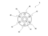
- the bearing bracket 40 has an annular bearing holding recess 41 for holding the bearing 30 on the center side thereof, and a casing holding recess 42 for fitting the casing 50 in an annular shape on the outer diameter side. Furthermore, a single or a plurality of through holes 43 are provided between the bearing holding recess 41 and the casing holding recess 42 (see FIG. 2).
- the through-hole 43 is a hole for drawing a lead wire of the stator 60 described later to the outside or dissipating the heat in the casing 50.
- the through-hole 43 is formed in a circular shape and spaced in the circumferential direction. A plurality are provided. As other examples of the through-hole 43, an arc-shaped long hole or a through-hole having another shape can be used.
- the casing 50 is formed in a thin cylindrical shape from, for example, a metal material such as iron or permalloy, or a synthetic resin material, and both ends thereof are on the outer peripheral sides of the bearing brackets 40 on the left and right sides (specifically, the casing holding recesses 42).
- the ring is fitted and fixed.
- a plurality of stators 60 are arranged around the rotor 20 at a predetermined interval in the axial direction.
- Each of these stators 60 is fixed to the outer peripheral surface of the rotor 20 with an appropriate clearance, and is fixed to the inner peripheral surface of the casing 50 so that it cannot rotate and cannot move in the axial direction.
- annular spacer 60a is provided between the two adjacent stators 60, 60 to keep the distance therebetween constant.
- the annular spacer 60a is formed in a substantially annular shape (for example, a star shape having a through hole in the center) having a plurality of notches 60a1 arranged in the circumferential direction on the outer peripheral side thereof, and the end surface 60a2 in the radially outer direction is formed on the casing. 50 is press-fitted into the inner surface and fixed (see FIG. 1).
- the plurality of cutout portions 61a1 are arranged at predetermined intervals in the circumferential direction so as to correspond to the salient pole portions 61b on the inner diameter side of the stator 60, and are used as spaces for inserting windings 62a, lead wires 62c and the like to be described later. (See FIG. 1).
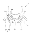
- Each stator 60 is formed by annularly arranging a plurality (three in the illustrated example) of independent stator constituent units A (see FIGS. 3 and 4).
- Each stator component unit A includes a split core 61 constituting a part of the stator core, a winding 62a wound around the inner diameter side of the split core 61, and the like.
- the split core 61 is formed by, for example, laminating a plurality of thin plate-like magnetic bodies such as silicon steel plates in the axial direction, and joining the steel plates by a joining means such as adhesion or doweling (fitting by unevenness).
- the split core 61 includes a split annular portion 61a formed along the inner peripheral surface of the casing 50, and a plurality of protrusions projecting radially inward from the split annular portion 61a and spaced in the circumferential direction. It is formed in a substantially fan shape having a pole portion 61b.
- the divided annular portion 61a has a shape obtained by dividing the annular member into a predetermined number (three according to the illustrated example) in the circumferential direction, and a concave groove 61a1 continuous on the outer circumferential surface in a direction intersecting the circumferential direction. A plurality.
- each concave groove 61 a 1 has a semicircular cross section, continues in a direction substantially parallel to the central axis of the stator 60, and penetrates the split core 61.
- Each concave groove 61a1 has a circumferential position that is substantially the same as the salient pole portion 61b that faces in the radially inward direction. That is, in the circumferential direction, the center position of each concave groove 61a1 and the center position of the salient pole portion 61b are substantially the same.
- the width, depth, and the like of the concave groove 61a1 are appropriately set so as to include the lead wire to be inserted.
- Each salient pole portion 61b is formed in a T-shaped cross section projecting radially inward, and a winding 62a is wound on the outer diameter side of the protruding portion on the projecting end side.
- the winding 62a is wound around each of the plurality of salient pole portions 61b.
- a connection line portion 62b connects between two windings 62a adjacent in the circumferential direction.
- lead wires 62c extend from both ends of the plurality of windings 62a.
- the plurality of windings 62a, the connecting wire portion 62b, and the lead wire 62c may be one continuous electric wire (for example, enamel-coated copper wire).
- the lead wire 62c can be a separate electric wire connected to the winding 62a.
- the two adjacent windings 62a and 62a in each stator constituent unit A are wound so as to constitute opposite poles. That is, according to an example shown in FIG. 4, the left one winding 62a is wound counterclockwise in the radially outward direction, and the right other winding 62a is clockwise in the radially outward direction. It is wound around.
- the end portion on the radially outer side of the left winding 62a is connected to the end portion on the radially inward side of the right winding 62a via the connecting wire portion 62b.
- the plurality of stator constituting units A configured as described above are gently press-fitted into the cylindrical casing 50, and the divided cores 61 and 61 adjacent in the circumferential direction are brought into contact with each other to constitute the stator 60 (see FIG. 3). .
- a plurality of (two in the illustrated example) windings 62a and 62a for each stator constituent unit A are connected to a plurality of windings 62a and 62a of another stator constituent unit A adjacent in the circumferential direction.
- they are separated and constitute separate and independent phases. That is, according to the illustrated example, the three stator constituent units A each independently constitute a U phase, a V phase, and a W phase.
- the lead wire 62c of each phase (in other words, for each stator component unit A) of the stator 60 on one side (the left side in FIG. 1) is connected to one bearing bracket 40. It is inserted through the through hole 43 and pulled out.
- the lead wires 62c of the respective phases of the stator 60 on the other side (right side in FIG. 1) are inserted into the recessed grooves 61a1 of the stator 60 on the one side (left side in FIG. 1), and further on the one bearing. It is inserted into the through hole 43 of the bracket 40 and pulled out.
- lead wires 62c are electrically connected to the same phase, and are connected to each phase of a three-phase power source for a brushless motor (not shown). That is, the plurality of stators 60 are connected in parallel to the brushless motor three-phase power source.
- each divided core 61 has a shape in which an annular ring is equally divided, it is possible to improve the yield when processing the core from raw materials, compared to the case of using an integral annular stator core.
- the plurality of windings 62a are configured to have the same phase for each stator configuration unit A, for example, compared with a case where a plurality of windings 62a having the same phase are connected across the plurality of stator configuration units A, Manufacturability can be improved and parts management can be facilitated.
- the plurality of windings 62a that form the same phase and do not extend over the plurality of divided cores 61 electrical or magnetic resistance or loss can be reduced, and motor efficiency can be improved. .
- the lead wires 62c of the plurality of stators 60 arranged in the axial direction can be guided in the same direction along the concave groove 61a1 on the outer peripheral surface of the split core 61.
- the inner rotor type brushless motor 1 is manufactured.
- the efficiency of the motor can be improved by relatively increasing the space factor of the winding 62a between the salient pole portions 61b adjacent in the circumferential direction.
- the concave groove 61a1 is provided on the base end side of the salient pole portion 61b having a relatively large radial thickness, the mechanical strength and magnetic force of the stator core due to the concave groove 61a1 can be reduced, and the slimmer Can be configured.
- groove 61a1 was provided in the linear form substantially parallel with respect to the centerline of the stator 60, as an other example, the aspect which inclined the ditch
- groove 61a1 was arrange
- groove 61a1 was arrange
- the split cores 61 and 61 adjacent in the circumferential direction are brought into contact with each other so that magnetic flux leaks from the outside to the outside and the electronic device or the like is not adversely affected.
- a structure may be employed in which a gap is formed between the split cores 61 adjacent to each other in the circumferential direction, and the lead wire 62c is inserted into the gap.
- stator 60 was connected in parallel with the three-phase power supply for brushless motors, as another example, a plurality of stators 60 may be connected in series with the three-phase power supply for brushless motors. Is possible.
- groove 61a1 was provided with respect to all the division
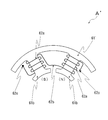
- stator constituent units A arranged in the circumferential direction with a stator constituent unit A ′ shown in FIG.
- the winding 62a can be passed between the salient pole portions 61b, 61b adjacent in the circumferential direction.
- adjacent windings 62a and 62a of each stator constituent unit A are configured as opposite poles
- the adjacent windings 62a and 62a are wound in opposite directions.
- adjacent windings 62 a and 62 a may be wound in the same direction so that they are excited to opposite poles. That is, in the stator component unit A ′′ shown in FIG. 6, both the left and right windings 62a are wound in the same direction (counterclockwise) toward the radially outer direction, and the left winding 62a is disposed on the radially inner side.
- the end portion is connected to the end portion on the radially inner side of the right winding 62a via the connecting wire portion 62b. Therefore, when these two continuous windings 62a and 62a are energized, the corresponding two salient pole portions 61b and 61b are opposite to each other (when one of the tips is an N pole, the other tip is an S pole). Will be excited.
- two adjacent windings 62a and 62a are configured to be independent and not continuous, and are wound in the same direction, and the two independent windings 62a and 62a are reverse in current direction. It is also possible to connect the adjacent windings 62a and 62a of the stator unit A to the opposite poles.
- a plurality of stators 60 composed of a plurality of stator constituent units A are arranged side by side in the axial direction.
- a stator 60 composed of a plurality of stator constituent units A is a single unit.
- One configuration is also possible.
- Inner rotor type brushless motor 20 Rotor 60: Stator 61, 61 ': Split core (stator core) 61a: Divided annular part 61a1: Groove 61b: Salient pole part 62a: Winding 62c: Lead wire A, A ', A ": Stator component unit
Landscapes
- Engineering & Computer Science (AREA)
- Power Engineering (AREA)
- Iron Core Of Rotating Electric Machines (AREA)
Abstract
Le problème décrit par l'invention est d'augmenter le rendement de moteur et les caractéristiques de production. La solution selon l'invention porte sur un moteur à rotor interne, qui comporte un rotor (20) qui possède un aimant et est monté en rotation, et un stator (60) qui est positionné à la périphérie du rotor (20) et est fixé de manière non rotative au boîtier du moteur. Le stator (60) résulte d'une pluralité d'unités de configuration de stator indépendantes (A) qui sont disposées d'une manière annulaire, chaque unité de configuration de stator (A) étant équipée d'un noyau divisé (61), qui possède une pluralité de sections de pôle saillant (61B) disposées à des intervalles dans la direction périphérique et faisant saillie vers l'intérieur dans la direction radiale, et une bobine (62A) enroulée autour de chacune de la pluralité de sections de pôle saillant (61B), et la pluralité de bobines (62A) dans chaque unité de configuration de stator (A) étant configurées en phase.
Applications Claiming Priority (2)
| Application Number | Priority Date | Filing Date | Title |
|---|---|---|---|
| JP2013-115976 | 2013-05-31 | ||
| JP2013115976 | 2013-05-31 |
Publications (1)
| Publication Number | Publication Date |
|---|---|
| WO2014192608A1 true WO2014192608A1 (fr) | 2014-12-04 |
Family
ID=51988641
Family Applications (1)
| Application Number | Title | Priority Date | Filing Date |
|---|---|---|---|
| PCT/JP2014/063419 Ceased WO2014192608A1 (fr) | 2013-05-31 | 2014-05-21 | Moteur sans balais à rotor interne |
Country Status (1)
| Country | Link |
|---|---|
| WO (1) | WO2014192608A1 (fr) |
Cited By (5)
| Publication number | Priority date | Publication date | Assignee | Title |
|---|---|---|---|---|
| EP3403932A1 (fr) * | 2017-05-17 | 2018-11-21 | General Electric Company | Système de propulsion pour aéronef |
| EP3444926A4 (fr) * | 2016-04-15 | 2019-11-27 | Schaeffler Technologies AG & Co. KG | Stator de générateur et générateur |
| JP2023087531A (ja) * | 2021-12-13 | 2023-06-23 | 株式会社デンソー | 回転電機 |
| JP2024504191A (ja) * | 2021-01-28 | 2024-01-30 | ベバスト エスエー | ブラシレスdcモータのためのステータを製造するための方法及び装置 |
| WO2024157212A1 (fr) * | 2023-01-27 | 2024-08-02 | Dyson Technology Limited | Ensemble stator |
Citations (6)
| Publication number | Priority date | Publication date | Assignee | Title |
|---|---|---|---|---|
| JPH07298578A (ja) * | 1994-04-28 | 1995-11-10 | Meidensha Corp | 回転電機 |
| JP2000217283A (ja) * | 1999-01-19 | 2000-08-04 | Shibaura Mechatronics Corp | モ―タの固定子及びそれを用いるモ―タの製造方法 |
| JP2002512499A (ja) * | 1998-04-21 | 2002-04-23 | ホガナス アクチボラゲット | 誘導機の固定子 |
| JP2004274970A (ja) * | 2003-03-12 | 2004-09-30 | Mitsubishi Electric Corp | 回転電機 |
| JP2010104142A (ja) * | 2008-10-23 | 2010-05-06 | Seiko Instruments Inc | ステータ、モータ及び記録媒体駆動装置 |
| JP2010148208A (ja) * | 2008-12-17 | 2010-07-01 | Mitsubishi Electric Corp | エレベータ用巻上モータ |
-
2014
- 2014-05-21 WO PCT/JP2014/063419 patent/WO2014192608A1/fr not_active Ceased
Patent Citations (6)
| Publication number | Priority date | Publication date | Assignee | Title |
|---|---|---|---|---|
| JPH07298578A (ja) * | 1994-04-28 | 1995-11-10 | Meidensha Corp | 回転電機 |
| JP2002512499A (ja) * | 1998-04-21 | 2002-04-23 | ホガナス アクチボラゲット | 誘導機の固定子 |
| JP2000217283A (ja) * | 1999-01-19 | 2000-08-04 | Shibaura Mechatronics Corp | モ―タの固定子及びそれを用いるモ―タの製造方法 |
| JP2004274970A (ja) * | 2003-03-12 | 2004-09-30 | Mitsubishi Electric Corp | 回転電機 |
| JP2010104142A (ja) * | 2008-10-23 | 2010-05-06 | Seiko Instruments Inc | ステータ、モータ及び記録媒体駆動装置 |
| JP2010148208A (ja) * | 2008-12-17 | 2010-07-01 | Mitsubishi Electric Corp | エレベータ用巻上モータ |
Cited By (10)
| Publication number | Priority date | Publication date | Assignee | Title |
|---|---|---|---|---|
| EP3444926A4 (fr) * | 2016-04-15 | 2019-11-27 | Schaeffler Technologies AG & Co. KG | Stator de générateur et générateur |
| US10978927B2 (en) | 2016-04-15 | 2021-04-13 | Schaeffler Technologies AG & Co. KG | Generator stator and generator |
| EP3403932A1 (fr) * | 2017-05-17 | 2018-11-21 | General Electric Company | Système de propulsion pour aéronef |
| US10807729B2 (en) | 2017-05-17 | 2020-10-20 | General Electric Company | Propulsion system for an aircraft |
| EP4112475A1 (fr) * | 2017-05-17 | 2023-01-04 | General Electric Company | Système de propulsion pour un aéronef |
| JP2024504191A (ja) * | 2021-01-28 | 2024-01-30 | ベバスト エスエー | ブラシレスdcモータのためのステータを製造するための方法及び装置 |
| JP7834107B2 (ja) | 2021-01-28 | 2026-03-23 | ベバスト エスエー | ブラシレスdcモータのためのステータを製造するための方法及び装置 |
| JP2023087531A (ja) * | 2021-12-13 | 2023-06-23 | 株式会社デンソー | 回転電機 |
| JP7790127B2 (ja) | 2021-12-13 | 2025-12-23 | 株式会社デンソー | 回転電機 |
| WO2024157212A1 (fr) * | 2023-01-27 | 2024-08-02 | Dyson Technology Limited | Ensemble stator |
Similar Documents
| Publication | Publication Date | Title |
|---|---|---|
| US9590457B2 (en) | Stator of a rotary electric machine | |
| JP2011010375A (ja) | アキシャル型モータ | |
| WO2015104893A1 (fr) | Moteur de type à entrefer axial | |
| US10153673B2 (en) | Production method for rotating electrical machine | |
| EP3166206B1 (fr) | Moteur électrique | |
| EP3525320B1 (fr) | Moteur de type à entrefer axial | |
| JP5267751B1 (ja) | 回転電機 | |
| WO2014192609A1 (fr) | Moteur sans balai à rotor intérieur | |
| JP2018166353A (ja) | 電動モータ | |
| WO2014192608A1 (fr) | Moteur sans balais à rotor interne | |
| KR20170031072A (ko) | 단상 영구 자석 모터 | |
| JP2018082600A (ja) | ダブルロータ型の回転電機 | |
| JP5248751B2 (ja) | スロットレス永久磁石型回転電機 | |
| JP2014100054A (ja) | 横磁束形電動機 | |
| JP2017046580A (ja) | 単相モータ | |
| US20060071576A1 (en) | Flat board type brushless dc motor | |
| US20150171673A1 (en) | System and method for retaining rotor structure in synchronous reluctance machine | |
| JP2012182945A (ja) | 回転電機 | |
| CN106803709B (zh) | 永磁同步电机及其装配方法 | |
| JP4415176B2 (ja) | リング状の固定子コイルを有する誘導電動機 | |
| JP2014073011A (ja) | 回転電機用ステータ及び回転電機 | |
| JP4482918B2 (ja) | リング状の固定子コイルを有する永久磁石型電動機 | |
| JP2006271142A (ja) | 回転機 | |
| JP6745212B2 (ja) | 回転子およびリラクタンス回転電機 | |
| JP2015027175A (ja) | 回転電機及び回転電機の製造方法 |
Legal Events
| Date | Code | Title | Description |
|---|---|---|---|
| 121 | Ep: the epo has been informed by wipo that ep was designated in this application |
Ref document number: 14805029 Country of ref document: EP Kind code of ref document: A1 |
|
| NENP | Non-entry into the national phase |
Ref country code: DE |
|
| 122 | Ep: pct application non-entry in european phase |
Ref document number: 14805029 Country of ref document: EP Kind code of ref document: A1 |
|
| NENP | Non-entry into the national phase |
Ref country code: JP |