WO2014192619A1 - Procédé opératoire pour dispositif de traitement de l'eau - Google Patents
Procédé opératoire pour dispositif de traitement de l'eau Download PDFInfo
- Publication number
- WO2014192619A1 WO2014192619A1 PCT/JP2014/063514 JP2014063514W WO2014192619A1 WO 2014192619 A1 WO2014192619 A1 WO 2014192619A1 JP 2014063514 W JP2014063514 W JP 2014063514W WO 2014192619 A1 WO2014192619 A1 WO 2014192619A1
- Authority
- WO
- WIPO (PCT)
- Prior art keywords
- water
- treated
- concentrated
- treated water
- quality index
- Prior art date
- Legal status (The legal status is an assumption and is not a legal conclusion. Google has not performed a legal analysis and makes no representation as to the accuracy of the status listed.)
- Ceased
Links
Images


Classifications
-
- B—PERFORMING OPERATIONS; TRANSPORTING
- B01—PHYSICAL OR CHEMICAL PROCESSES OR APPARATUS IN GENERAL
- B01D—SEPARATION
- B01D61/00—Processes of separation using semi-permeable membranes, e.g. dialysis, osmosis or ultrafiltration; Apparatus, accessories or auxiliary operations specially adapted therefor
- B01D61/58—Multistep processes
-
- B—PERFORMING OPERATIONS; TRANSPORTING
- B01—PHYSICAL OR CHEMICAL PROCESSES OR APPARATUS IN GENERAL
- B01D—SEPARATION
- B01D61/00—Processes of separation using semi-permeable membranes, e.g. dialysis, osmosis or ultrafiltration; Apparatus, accessories or auxiliary operations specially adapted therefor
- B01D61/02—Reverse osmosis; Hyperfiltration ; Nanofiltration
- B01D61/06—Energy recovery
-
- B—PERFORMING OPERATIONS; TRANSPORTING
- B01—PHYSICAL OR CHEMICAL PROCESSES OR APPARATUS IN GENERAL
- B01D—SEPARATION
- B01D61/00—Processes of separation using semi-permeable membranes, e.g. dialysis, osmosis or ultrafiltration; Apparatus, accessories or auxiliary operations specially adapted therefor
- B01D61/02—Reverse osmosis; Hyperfiltration ; Nanofiltration
- B01D61/12—Controlling or regulating
-
- C—CHEMISTRY; METALLURGY
- C02—TREATMENT OF WATER, WASTE WATER, SEWAGE, OR SLUDGE
- C02F—TREATMENT OF WATER, WASTE WATER, SEWAGE, OR SLUDGE
- C02F1/00—Treatment of water, waste water, or sewage
- C02F1/008—Control or steering systems not provided for elsewhere in subclass C02F
-
- B—PERFORMING OPERATIONS; TRANSPORTING
- B01—PHYSICAL OR CHEMICAL PROCESSES OR APPARATUS IN GENERAL
- B01D—SEPARATION
- B01D2311/00—Details relating to membrane separation process operations and control
- B01D2311/04—Specific process operations in the feed stream; Feed pretreatment
-
- B—PERFORMING OPERATIONS; TRANSPORTING
- B01—PHYSICAL OR CHEMICAL PROCESSES OR APPARATUS IN GENERAL
- B01D—SEPARATION
- B01D2311/00—Details relating to membrane separation process operations and control
- B01D2311/25—Recirculation, recycling or bypass, e.g. recirculation of concentrate into the feed
- B01D2311/253—Bypassing of feed
- B01D2311/2532—Bypassing of feed to concentrate side
-
- B—PERFORMING OPERATIONS; TRANSPORTING
- B01—PHYSICAL OR CHEMICAL PROCESSES OR APPARATUS IN GENERAL
- B01D—SEPARATION
- B01D2311/00—Details relating to membrane separation process operations and control
- B01D2311/26—Further operations combined with membrane separation processes
- B01D2311/263—Chemical reaction
-
- B—PERFORMING OPERATIONS; TRANSPORTING
- B01—PHYSICAL OR CHEMICAL PROCESSES OR APPARATUS IN GENERAL
- B01D—SEPARATION
- B01D2311/00—Details relating to membrane separation process operations and control
- B01D2311/26—Further operations combined with membrane separation processes
- B01D2311/2642—Aggregation, sedimentation, flocculation, precipitation or coagulation
-
- B—PERFORMING OPERATIONS; TRANSPORTING
- B01—PHYSICAL OR CHEMICAL PROCESSES OR APPARATUS IN GENERAL
- B01D—SEPARATION
- B01D2311/00—Details relating to membrane separation process operations and control
- B01D2311/26—Further operations combined with membrane separation processes
- B01D2311/2649—Filtration
-
- B—PERFORMING OPERATIONS; TRANSPORTING
- B01—PHYSICAL OR CHEMICAL PROCESSES OR APPARATUS IN GENERAL
- B01D—SEPARATION
- B01D2311/00—Details relating to membrane separation process operations and control
- B01D2311/26—Further operations combined with membrane separation processes
- B01D2311/2676—Centrifugal separation
-
- B—PERFORMING OPERATIONS; TRANSPORTING
- B01—PHYSICAL OR CHEMICAL PROCESSES OR APPARATUS IN GENERAL
- B01D—SEPARATION
- B01D2311/00—Details relating to membrane separation process operations and control
- B01D2311/26—Further operations combined with membrane separation processes
- B01D2311/2688—Biological processes
-
- C—CHEMISTRY; METALLURGY
- C02—TREATMENT OF WATER, WASTE WATER, SEWAGE, OR SLUDGE
- C02F—TREATMENT OF WATER, WASTE WATER, SEWAGE, OR SLUDGE
- C02F1/00—Treatment of water, waste water, or sewage
- C02F1/28—Treatment of water, waste water, or sewage by sorption
- C02F1/283—Treatment of water, waste water, or sewage by sorption using coal, charred products, or inorganic mixtures containing them
-
- C—CHEMISTRY; METALLURGY
- C02—TREATMENT OF WATER, WASTE WATER, SEWAGE, OR SLUDGE
- C02F—TREATMENT OF WATER, WASTE WATER, SEWAGE, OR SLUDGE
- C02F1/00—Treatment of water, waste water, or sewage
- C02F1/44—Treatment of water, waste water, or sewage by dialysis, osmosis or reverse osmosis
- C02F1/444—Treatment of water, waste water, or sewage by dialysis, osmosis or reverse osmosis by ultrafiltration or microfiltration
-
- C—CHEMISTRY; METALLURGY
- C02—TREATMENT OF WATER, WASTE WATER, SEWAGE, OR SLUDGE
- C02F—TREATMENT OF WATER, WASTE WATER, SEWAGE, OR SLUDGE
- C02F1/00—Treatment of water, waste water, or sewage
- C02F1/72—Treatment of water, waste water, or sewage by oxidation
- C02F1/74—Treatment of water, waste water, or sewage by oxidation with air
-
- C—CHEMISTRY; METALLURGY
- C02—TREATMENT OF WATER, WASTE WATER, SEWAGE, OR SLUDGE
- C02F—TREATMENT OF WATER, WASTE WATER, SEWAGE, OR SLUDGE
- C02F1/00—Treatment of water, waste water, or sewage
- C02F1/72—Treatment of water, waste water, or sewage by oxidation
- C02F1/78—Treatment of water, waste water, or sewage by oxidation with ozone
-
- C—CHEMISTRY; METALLURGY
- C02—TREATMENT OF WATER, WASTE WATER, SEWAGE, OR SLUDGE
- C02F—TREATMENT OF WATER, WASTE WATER, SEWAGE, OR SLUDGE
- C02F3/00—Biological treatment of water, waste water, or sewage
- C02F3/02—Aerobic processes
- C02F3/12—Activated sludge processes
-
- Y—GENERAL TAGGING OF NEW TECHNOLOGICAL DEVELOPMENTS; GENERAL TAGGING OF CROSS-SECTIONAL TECHNOLOGIES SPANNING OVER SEVERAL SECTIONS OF THE IPC; TECHNICAL SUBJECTS COVERED BY FORMER USPC CROSS-REFERENCE ART COLLECTIONS [XRACs] AND DIGESTS
- Y02—TECHNOLOGIES OR APPLICATIONS FOR MITIGATION OR ADAPTATION AGAINST CLIMATE CHANGE
- Y02W—CLIMATE CHANGE MITIGATION TECHNOLOGIES RELATED TO WASTEWATER TREATMENT OR WASTE MANAGEMENT
- Y02W10/00—Technologies for wastewater treatment
- Y02W10/10—Biological treatment of water, waste water, or sewage
Definitions
- the present invention relates to a method for operating a water treatment apparatus using a semipermeable membrane unit for treating seawater, river water, groundwater, or sewage wastewater treated water to obtain fresh water.
- the present invention relates to an operation method of a water treatment apparatus that enables stable operation.
- reverse osmosis membranes obtain fresh water by applying pressure against the osmotic pressure resulting from the difference in membrane surface concentration.
- the effective pressure for separation is the operating pressure minus the osmotic pressure based on the feed water concentration.
- Patent Document 1 and Non-Patent Document 1 disclose a method for efficiently taking out fresh water against the concentrated high osmotic pressure in the latter stage by raising the operating pressure in the middle.
- Non-Patent Document 2 discloses a technology for reducing treatment costs by treating the permeated water twice using a nanofiltration membrane that is larger in separation size than a reverse osmosis membrane and is generally unsuitable for seawater desalination. ing.
- Non-Patent Document 3 discloses a processing cost reduction technique that increases energy efficiency by using river water and seawater together. Many of these technologies have been put into practical use.
- Non-Patent Document 6 A TML series manufactured by Toray Industries, Inc., Non-Patent Document 6
- a process of reusing sewage wastewater as shown in Non-Patent Document 4 and Non-Patent Document 5 has been put into practical use.
- concentrated water for reuse of sewage wastewater is concentrated water, it contains a large amount of impurities, particularly organic substances, and care must be taken when draining the concentrated water out of the system.
- the concentrated water does not meet the effluent quality standards for the environment, it is necessary to reduce the concentration factor or perform post-treatment so that there is no problem with the effluent quality standards before discharging the concentrated water. There is.
- Non-Patent Document 2 Non-Patent Documents 7 and 8
- the process described in Non-Patent Documents 7 and 8 in which the concentrated water of the low pressure reverse osmosis membrane is mixed to lower the osmotic pressure can greatly reduce the required energy compared to the conventional seawater desalination process. Because it is highly expected.
- the concentrated water reused from sewage wastewater is mixed with seawater.
- the amount of impurities in the concentrated water becomes a problem. That is, the impurities contained in the concentrated water of the low-pressure reverse osmosis membrane contained all the impurities when the concentrated water was directly mixed with seawater to obtain seawater mixed water, and fresh water was taken out again through the high-pressure reverse osmosis membrane. As it is, it is concentrated again and discharged out of the system. Therefore, the concentrated water of the seawater mixed water may exceed the drainage water quality standard, similarly to the concentrated water of the low-pressure reverse osmosis membrane.
- an object of the present invention relates to an operation method of a water treatment apparatus that obtains treated water from a plurality of types of treated water, and relates to an operation method of a water treatment apparatus that can be stably operated at low cost.
- an object of the present invention is to provide an operation method that does not adversely affect the environment when operating a water treatment apparatus for producing fresh water to which a semipermeable membrane is applied.
- the water treatment apparatus of the present invention has any one of the following ⁇ 1> to ⁇ 17>.
- ⁇ 1> A pretreatment unit X that makes the first treated water A treated water A0 by pretreatment, a membrane separation unit Y that separates the treated water A0 into permeated water A2 and concentrated water A3, the concentrated water A3 and the The mixed water B1 containing at least one of the treated water A4 of the concentrated water A3 and at least one of the second treated water B and the treated water B0 of the treated water B is converted into the permeated water B2 and the concentrated water.
- a water quality index C B3 of the concentrated water B3 or the water quality index C B4 of the treated water B4 of the concentrated water B3 exceeds a predetermined reference value, at least selected from the following methods (1) to (8) A method for operating a water treatment apparatus, wherein the method 1 is performed.
- the method (1) the film method of reducing the recovery rate R Z of the permeate B2 in the recovery rate R Y a method of lowering (2) the membrane separation unit Z of the permeate A2 in the separation unit Y (3) the mixed water B1 (4) Changing the mixing ratio between at least one of the concentrated water A3 and the treated water A4 and at least one of the treated water B and the treated water B0 in (4)
- the concentrated water A3 is treated with the treated water B and adsorbing or decomposing at least part of the concentrated water A3 before mixing with at least one of the treated water B0.
- the concentrated water B3 Before discharging the concentrated water B3, the concentrated water B3 Method (6) of adsorbing or decomposing at least a part of the mixture
- Water B1 is mixed water containing the treated water A4, the treated water B0 and the third treated water C.
- the mixed water B1 is mixed water containing the treated water A4, the treated water B0, and a part of the treated water A0.
- Method (8) At least a part of the concentrated water A3 is returned to the pretreatment unit X.
- the reference value of the water quality index C B3 or the water quality index C B4 is determined by biological oxygen demand, chemical oxygen demand, total organic carbon, total nitrogen, total phosphorus, or absorbance.
- the operation method of the water treatment apparatus according to ⁇ 1>.
- ⁇ 6> The method for operating a water treatment apparatus according to any one of ⁇ 1> to ⁇ 5>, wherein both the methods (4) and (5) are performed.
- ⁇ 7> The water according to any one of ⁇ 1> to ⁇ 6>, wherein the concentrated water A3 or the concentrated water B3 is turbidized before the method (4) or (5) is performed. Operation method of the processing apparatus.
- ⁇ 8> In the method (6), the supply amount of the treated water C is determined so that the operating pressure of the membrane separation unit Z does not exceed a preset reference value.
- ⁇ 9> The water treatment device according to any one of ⁇ 1> to ⁇ 8>, wherein in the method (7), the flow rate of the permeated water A2 is reduced by an amount corresponding to the flow rate of mixing the treated water A0. Driving method. ⁇ 10> In the method (8), the chemical treatment is performed while the concentrated water A3 is refluxed to the pretreatment unit X. The water treatment device according to any one of ⁇ 1> to ⁇ 9>, how to drive. ⁇ 11> The water treatment according to any one of ⁇ 1> to ⁇ 10>, wherein at least one of the water to be treated A and the water to be treated C has a lower osmotic pressure than the water to be treated B. How to operate the device.
- ⁇ 15> The method for operating a water treatment apparatus according to any one of ⁇ 1> to ⁇ 14>, wherein at least one of the membrane separation unit Y and the membrane separation unit Z is a semipermeable membrane unit.
- ⁇ 16> The method for operating a water treatment apparatus according to any one of ⁇ 1> to ⁇ 15>, wherein the maximum operating pressure of the membrane separation unit Z is higher than the maximum operating pressure of the membrane separation unit Y.
- ⁇ 17> The operation of the water treatment apparatus according to any one of ⁇ 1> to ⁇ 16>, wherein a part of the treated water A0 is mixed with at least one of the concentrated water B3 and the treated water B4.
- the operation method of the water treatment apparatus of the present invention when obtaining treated water from a plurality of types of treated water, low-cost and stable operation can be enabled while complying with the wastewater quality standards for the environment.
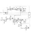
- FIG. 1 is a schematic flow diagram illustrating an embodiment of a method for operating a water treatment apparatus capable of performing the methods (1) to (3) according to the present invention.
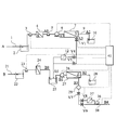
- FIG. 2 is a schematic flow diagram illustrating an embodiment of a method for operating a water treatment apparatus capable of performing the methods (1) to (5) according to the present invention.
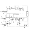
- FIG. 3 is a schematic flow diagram illustrating an embodiment of a method for operating a water treatment apparatus capable of performing the methods (1) to (3) and (6) according to the present invention.
- FIG. 4 is a schematic flow diagram illustrating an embodiment of a method for operating a water treatment apparatus capable of performing the methods (1) to (3) and (6) to (8) according to the present invention.
- FIG. 5 is a schematic flow diagram illustrating an embodiment of a method for operating a water treatment apparatus capable of performing the methods (1) to (8) in the present invention.
- FIG. 1 is a schematic flow diagram showing an example of an operation method of a water treatment apparatus (fresh water production apparatus) capable of performing the methods (1) to (3) in the present invention.
- the present invention includes a pretreatment unit X that converts the first treated water A into treated water A0 by pretreatment, a membrane separation unit Y that separates the treated water A0 into permeated water A2 and concentrated water A3, and the concentration.
- Mixed water B1 containing at least one of water A3 and treated water A4 of concentrated water A3 and at least one of second treated water B and treated water B0 of treated water B is treated as permeated water.
- the present invention relates to a method for operating a water treatment apparatus when the value exceeds a predetermined reference value.
- first treated water A and second treated water B are treated through the first treated water line 1 and the second treated water line 21, respectively.
- the treated water A is temporarily stored in the first treated water tank 2 as necessary, and then passes through the first water intake pump 3 to the pretreatment unit X (first pretreatment unit 4). Treated and treated water A0 is discharged.
- the treated water A0 is sent to the membrane separation unit Y (first membrane separation unit 7) by the supply pump 5 and the pressure pump 6.
- a method of treating the treated water A to the treated water A0 in the pretreatment unit X will be described later together with the pretreatment unit X.
- the membrane separation unit Y is treated water A0 or supply water A1 for pumping up the treated water A0 with the supply pump 5 and supplying it to the membrane separation unit Y (hereinafter, treated water A0 and supply water A1 are the same without being distinguished from each other). Is separated into permeated water A2 and concentrated water A3, and the permeated water A2 is stored in the first production water tank 10.
- the flow rate and the flow rate ratio of the permeated water A2 and the concentrated water A3 can be controlled by the output of the pressurizing pump 6 and the opening degree of the valve V1.
- the output of the pressurizing pump 6 is increased, and when the flow rate ratio of the permeated water A2 is increased, the opening of the valve V1 is decreased to reduce the target flow rate.
- the flow ratio can be reached.
- At least one of the concentrated water A3 and the treated water A4 treated with the concentrated water A3 is mixed with the treated water B and at least one of the treated water B0 treated with the treated water B, and the mixed water B1 And
- the mixed water B1 may contain a third treated water C.
- the mixed water B1 is mixed in the mixing tank 25 in FIG. 1, but may be mixed in a line having a large diameter where the lines through which the water flows are combined, and if the mixed water B1 is obtained, the mixed water B1 may be mixed. It is not limited.
- the mixed water B1 thus obtained is sent to the membrane separation unit Z (second membrane separation unit 27) by the second pressurizing pump 26 and separated into the permeated water B2 and the concentrated water B3.
- Examples of the treatment method for converting the concentrated water A3 into the treated water A4 include adsorption and decomposition treatment.
- Examples of the adsorbing means include a method of adsorbing to activated carbon, a flocculant, an ion exchange resin and the like.
- Examples of the decomposition treatment include a treatment method in which the molecular weight is reduced by accelerated oxidation using ozone, supercritical oxidation, electrolysis, or the like.
- Examples of the treatment method for converting the treated water B into the treated water B0 include the same method as the treatment method for converting the concentrated water A3 into the treated water A4.
- the permeated water B2 is stored in the second production water tank 28.
- the flow rate and the flow rate ratio of the permeated water B2 and the concentrated water B3 at this time can be controlled by the output of the pressurizing pump 26 and the opening degree of the valve V7, as in the membrane separation unit Y described above.
- an energy recovery unit 29 can be provided to recover the pressure energy of the concentrated water B3.
- the energy recovery unit 29 is not particularly limited, and can be applied from a conventional unit such as a reverse pump and a Pelton turbine to a highly efficient one such as a turbocharger and a pressure exchange type, but the fluctuation in the operating pressure of the membrane separation unit Z can be suppressed. Thus, it becomes easy to maintain these energy recovery efficiencies. In particular, since the reverse pump and the Pelton turbine cannot maintain high efficiency against pressure and flow rate fluctuations, it is very effective from the standpoint of energy recovery to suppress the operating pressure fluctuations.
- Concentrated water B3 is drained out of the system, but it may be treated before being drained and drained as treated water B4.
- Examples of the treatment method for converting the concentrated water B3 to the treated water B4 include the same method as the treatment method for converting the concentrated water A3 to the treated water A4.
- the treated water A is sewage, industrial waste water, sewage water mainly composed of contaminated river water, ground water, lake water, or the like, or treated water of the sewage water, and treated water B described later. It is preferable to apply more polluted water.
- the main component means a component having the largest content volume ratio.
- the degree of pollution can be known based on the value of the target water quality index, but the water quality index C A of the treated water A is preferably higher than the water quality index C B of the treated water B. .
- the salinity concentration of the for-treatment water B is higher than the salinity concentration of the for-treatment water A.
- the water quality index will be described later.
- the concentrated water A3 of the membrane separation unit Y and / or its treated water A4 and the water to be treated B and / or its treated water B0 are mixed and treated at a high pressure. It will be.
- the high-pressure semipermeable membrane used for seawater desalination or the like is preferable because it has a higher blocking performance than the case of reusing general sewage wastewater, and the quality of the entire produced water is good.
- the water to be treated is preferably seawater, high-concentration brine, or water mainly composed of brackish water. That is, it is preferable that the water to be treated A includes sewage wastewater or treated water of the sewage wastewater, and the water to be treated B includes seawater.
- the treated water A and the treated water B are preferably such that the treated water A has a lower osmotic pressure than the treated water B.
- the membrane separation unit Z is exposed to higher salt concentration water and has a higher osmotic pressure.
- the maximum operating pressure is preferably higher than the maximum operating pressure of the membrane separation unit Y.
- the water treatment apparatus used in the method of the present invention necessarily includes a pretreatment unit X, a membrane separation unit Y, and a membrane separation unit Z.
- the membrane separation unit Y and the membrane separation unit Z are not particularly limited as long as the treated water treated by the pretreatment unit X can be further purified.
- the membrane separation unit Y and the membrane separation unit Z are preferably nanofiltration membranes that can separate even smaller molecules than microfiltration membranes and ultrafiltration membranes, semipermeable membrane units such as reverse osmosis membranes, and separations with enhanced surface charge A charged ultrafiltration membrane with improved performance is used.
- At least one of the membrane separation unit Y and the membrane separation unit Z is preferably a semipermeable membrane unit from the viewpoint of good water quality for reusing the produced water.
- the shape of the membrane is not particularly limited, such as a flat membrane or a hollow fiber membrane.
- the membrane separation unit Y is preferably excellent in fouling resistance due to organic matter.
- a separation membrane having fouling resistance is preferably exemplified.
- a reverse osmosis membrane having seawater specifications can be generally applied as the membrane separation unit Z.
- the operation pressure of the membrane separation unit Z can be kept low by mixing other water with the water to be treated B, a reverse osmosis membrane of relatively low pressure specification for brine can be applied.
- the pressure operating pressure of the pressure pump and the pipe connected to the membrane separation unit Y and the membrane separation unit Z is higher in the membrane separation unit Z than in the membrane separation unit Y. It is preferable to design so that it can be increased. Furthermore, as the material, since the membrane separation unit Z is exposed to a higher salinity concentration, it is preferable that the corrosion durability is also higher. Specifically, it is preferable to use high-grade stainless steel having higher corrosion durability (corrosion resistance) for the membrane separation unit Z than for the membrane separation unit Y.
- peripheral member of the membrane separation unit Y a material having a standard corrosion resistance such as SUS304L or SAF2304 or a material having a slightly enhanced corrosion resistance such as SUS316 or SUS317 is used. It is preferable to use high-grade stainless steel such as SUS316L, SUS317L, SAF2507, SUS836L, SUS890L, SUS329J3L, and SUS329J4L, which have further enhanced corrosion resistance, as the peripheral member of the separation unit Z.
- high-grade stainless steel such as SUS316L, SUS317L, SAF2507, SUS836L, SUS890L, SUS329J3L, and SUS329J4L, which have further enhanced corrosion resistance, as the peripheral member of the separation unit Z.
- the concentrated water B3 of the membrane separation unit Z is normally discharged into the environment, it is necessary to satisfy the wastewater quality standards of the country, state, local government, etc. where the water treatment apparatus is installed.
- the maximum value of biological oxygen demand (BOD) is 120 mg / L
- the maximum value of soluble iron is 10 mg / L.
- the operation method of the water treatment apparatus of this invention is described supposing the case where the to-be-treated water A contains sewage wastewater or the treated water of the sewage wastewater, and the to-be-treated water B contains seawater. Since the to-be-processed water A normally contains the components defined in the wastewater quality standard in excess of the standard value, it is preferable to remove them in the pretreatment unit X. There are no particular restrictions on the pretreatment unit X, chemical treatment such as coagulation sedimentation and pressurized flotation, sedimentation tank, screen, sand filtration, membrane filtration, physical separation such as membrane filtration, centrifugation, biological treatment, or their It can be selected appropriately from the combination.
- chemical treatment such as coagulation sedimentation and pressurized flotation, sedimentation tank, screen, sand filtration, membrane filtration, physical separation such as membrane filtration, centrifugation, biological treatment, or their It can be selected appropriately from the combination.
- a unit composed of a combination of biological treatment and solid-liquid separation treatment is preferable from the viewpoint that the organic substance concentration and the suspension concentration can be reduced.
- treated water A0 that satisfies the wastewater quality standard can be obtained.
- the pretreatment units 24 and 34 for treating the water to be treated B and the water to be treated C are not particularly limited, and are similar to the pretreatment unit 4 and include chemical treatment, physical treatment, biological treatment, and combinations thereof. A unit etc. can be selected suitably.
- the biological treatment method here is typically the activated sludge method.
- the activated sludge method microorganisms contained in activated sludge are used to decompose organic substances in waste water and pollutants such as nitrogen and phosphorus.
- Activated sludge is generally used for wastewater treatment and the like.
- the sludge concentration is about 2,000 mg / L to 5,000 mg / L, and the residence time of the water to be treated A is usually 1 hour to 24 hours.
- the sludge concentration is about 2,000 mg / L to 20,000 mg / L, and the residence time of the water to be treated A is usually operated for 1 to 24 hours.
- an activated sludge method is performed in the pretreatment tank 13, and the treated water is supplied to a first filter such as a microfiltration membrane or an ultrafiltration membrane.
- a so-called membrane separation activated sludge method in which solid-liquid separation is performed by one pretreatment unit 4 is preferably used.
- the microfiltration membrane is defined as a separation membrane having a driving force that is a pressure at which particles of 0.1 ⁇ m or more can be removed.
- An ultrafiltration membrane is usually defined as a membrane having pores of 0.001 to 0.1 ⁇ m.
- the membrane applied by the immersion filtration method is not limited to a hollow fiber membrane or a flat membrane, but a flat membrane is preferred from the viewpoint that the unit structure is simple and suitable for high concentration treatment. .
- the concentrated water A3 and / or the treated water A4 is mixed with the treated water B and / or the treated water B0, so the concentration of the target substance in the concentrated water A3 remains high, There is no direct discharge into the environment.
- the concentrated water A3 and / or the treated water A4 are mixed with the treated water B and / or the treated water B0, supplied from the mixing tank 25 to the membrane separation unit Z, and separated into the permeated water B2 and the concentrated water B3. That is, the target substance brought in from the concentrated water A3 and / or the treated water A4 is further concentrated in the membrane separation unit Z and discharged as the concentrated water B3 or the treated water B4.
- the concentrated water A3 and the treated water A4 are not distinguished from each other and are represented as A4.
- the treated water B and the treated water B0 are denoted as B0 without being distinguished from each other. Is denoted as B4 without distinction.
- the maximum concentration of the target substance contained in the concentrated water B3 or the treated water B4 (hereinafter also referred to as “water quality index”) C B3 or C B4 can be expressed by the following formula.
- C A0 is a water quality index [mg / L] in the treated water A0
- C B0 is a water quality index [mg / L] in the treated water B0
- F A0 is a water quality index in the pretreated water A0 [m 3 / d]
- F B0 is the water quality index [m 3 / d] in the pretreated water B
- R Y is the recovery rate of the permeate A 2 in the membrane separation unit Y [%]
- R Z is the permeate B 2 in the membrane separation unit Z Represents the recovery rate [%].
- the water quality index of the treated water A0 and the water quality index of the treated water B0 can be obtained by an online sensor, an off-line measuring instrument, or the like.
- the water quality index C B4 when the concentrated water B3 is treated into the treated water B4 is expressed by the same formula as the above C B3 when the concentration of the substance that is the target of the water quality index does not change due to the treatment.
- CB4 is obtained by an online sensor, an offline measuring instrument, or the like.
- the water quality index C B3 or C B4 of the concentrated water B3 or the treated water B4 discharged into the environment exceeds a predetermined reference value (drainage water quality standard)
- a predetermined reference value drainage water quality standard
- the method (1) film lowers the recovery rate of the permeate A2 in the separation unit Y R Y ( flow rate ⁇ 100 of the flow rate / treated water A0 permeate A2 (%)).
- Method (3) The mixing ratio of at least one of the concentrated water A3 and the treated water A4 and at least one of the treated water B and the treated water B0 in the mixed water B1 is changed.
- Y )) is obtained by an on-line sensor or an off-line measuring instrument, and the water quality index C B of the second treated water B or the water quality index C B0 of the treated water B0 is measured.
- the concentrated water A3 or the concentrated water A3 with respect to the flow rate of the second treated water B or the treated water B0 It is preferable to reduce the flow rate ratio of the treated water A4.
- the direction of the water quality indicator C A3 or the water quality indicator C A4 is smaller than the quality indicator C B or the water quality indicator C B0, the flow rate of the second treated water B or the treated water B0 It is preferable to increase the ratio of the flow rate of the concentrated water A3 or the treated water A4.
- the water quality index (C B3 and / or C B4 ) related to the drainage standard is monitored by the second water quality index sensor 36, and the value is set in advance.
- the recovery rate of at least one of the membrane separation unit Y and the membrane separation unit Z is reduced via the control unit 41.
- the permeate flow rate can be increased by increasing the recovery rate. Further, in some cases, it is possible to adjust the flow rate of the water to be treated by increasing or decreasing it.
- At least one flow rate selected from the group consisting of the concentrated water A3 of the membrane separation unit Y, the concentrated water A3 of the membrane separation unit Z, and the treated water A4 is within a predetermined range. It is preferable to maintain. If the flow rate is too small, concentration polarization will occur in the membrane separation unit or accumulation of dirt substances will be accelerated.If the flow rate is too large, excessive pressure loss or damage will occur in the membrane separation unit. It is preferable to set so as not to exceed. In other words, this method may be difficult to apply depending on the amount of water to be treated A or B to be treated unless adjustments such as reducing or increasing the overall treatment amount are required. is there.
- Method (4) Before mixing the concentrated water A3 with at least one of the treated water B and the treated water B0, at least a part of the concentrated water A3 is adsorbed or decomposed.
- Method (5) Before discharging the concentrated water B3, at least a part of the concentrated water B3 is adsorbed or decomposed.
- a typical adsorption means a method of adsorbing to activated carbon, a flocculant, an ion exchange resin or the like can be mentioned.
- Examples of the decomposition treatment include a treatment method in which the molecular weight is reduced by accelerated oxidation using ozone, supercritical oxidation, electrolysis, or the like.
- the water treated from the concentrated water A3 in the method (4) and the treated water A4 may be the same, and the water treated from the concentrated water B3 in the method (5) may be the same as the treated water B4.
- the concentrated water A3 or concentrated water B3 that has passed through the membrane separation unit Y or the membrane separation unit Z is a suspended matter that may be present in a trace amount, rust, microorganisms, scale, etc. that may arise as a result of long-term operation. May also be concentrated together. These can be inhibitors of adsorption and decomposition processes. Therefore, before carrying out the above method (4) or (5), it is preferable to remove these substances by turbidizing the concentrated water A3 or the concentrated water B3.
- FIG. 2 An example of the flow when the method (4) or (5) is performed is shown in FIG.
- the concentration of target substances in the concentrated water A3 of the membrane separation unit Y and the concentrated water B3 of the membrane separation unit Z is reduced by the first purification unit 12 and the second purification unit 37.
- These purification units 12 and 37 can be controlled by valves V4, V5, V8, and V9. That is, when it is not necessary to reduce the concentration, the valves V4 and V8 are fully closed, and when the concentration exceeds, the concentration of the target substance can be reduced by gradually opening at least one of V4 and V8.
- the operating method is not particularly limited, but can be set as appropriate depending on the processing cost, operability, and the like.
- the second purification unit 37 can be used as a backup for the first purification unit 12, and if the target substance to be removed may adversely affect the membrane separation unit Z, its risk Can also be reduced. Furthermore, it is preferable to remove the substances other than the target substance because the load on the membrane separation unit Z can be reduced and it can be expected to contribute to improving the water quality of the permeated water B2.
- Method (6) The mixed water B1 is mixed water containing the treated water A4, the treated water B0, and the third treated water C.
- the third treated water C it is preferable to use water with little or no content of the target substance.
- FIG. 3 An example of the flow when the method (6) is performed is shown in FIG.
- the to-be-treated water C passes through the third to-be-treated water line 31 and is added to the mixing tank 25 via the third pretreatment unit 34 as necessary.
- the treated water C is added to the second treated water tank 22 and mixed with the treated water B.
- the treated water C can be mixed with the treated water A4.
- the mixed water B1 may be directly added to the line of the treated water A4, the treated water B0, the mixed water of the treated water A4 and B0 without mixing in the tank. That is, if the mixed water B1 containing treated water A4, treated water B0, and treated water C can be obtained, it will not be limited to the addition method and location of treated water C.
- the amount of the permeated water A2 or the permeated water B2 is reduced.
- the membrane separation unit Z Since it is possible to reduce the restriction of the concentration ratio and maintain the amount of permeated water, it is a very preferable method when the treated water C having a low target substance concentration can be supplied. Specifically, when the second water quality indicator sensor 36 that monitors the concentrated water B3 or the treated water B4 exceeds the set value, the third intake pump 33 and the valve V6 are operated via the control unit 41. By adjusting and / or adjusting the output of the second intake pump 23, the concentration of the target substance in the mixing tank 25 can be reduced.
- the processing pressure is set so that the operating pressure of the membrane separation unit Z does not exceed a preset reference value. It is also preferable to determine the supply amount of water C.
- the maximum operating pressure of the membrane separation unit is determined by the manufacturer's pressure resistance of the unit or module. Also, the permeation flux of the membrane has an instruction from the manufacturer, and the maximum value is determined.
- the target substance contained in the concentrated water A3 of the membrane separation unit Y is basically the treated water A0 (feed water A1) concentrated in the membrane separation unit Y, the concentration of the target substance in the concentrated water A3 In order to reduce this, it is necessary to reduce the concentration of the target substance in the treated water A0 (feed water A1), that is, it is required that the target substance can be removed by the pretreatment unit X. If the removal performance of the pretreatment unit X is sufficient, there is no problem, but if the removal performance is insufficient, the target substance is concentrated in the membrane separation unit Y. Therefore, when the removal performance is insufficient, the following method (7) can be performed.
- mixed water B1 be mixed water containing treated water A4, treated water B0, and a part of treated water A0. That is, a part of the pretreated water A0 is supplied as mixed water without concentrating the entire amount of the treated water A0 in the membrane separation unit Y. Thereby, the concentration of the target substance in the mixing tank 25 can be reduced (water quality index can be improved).
- a mixed water B1 containing a part of the treated water A0, the treated water A4 and the treated water B0 may be obtained, and a method of adding a part of the treated water A0. It is not limited to or place.
- the flow rate of the concentrated water A3 is bypassed from the treated water A0 and sent to the mixing tank 25, that is, the treated water. It is preferable to reduce the flow rate of the permeated water A2 by the amount of the mixed flow rate of A0.
- Method (8) At least part of the concentrated water A3 is refluxed to the pretreatment unit X.
- the concentration of the concentrated water A3 can be reduced by returning at least a part of the concentrated water A3 to the first treated water tank 2 and treating it again with the pretreatment unit X, This is very preferable because the concentration of the target substance can be reduced.
- FIG. 4 shows a flow example when the above methods (7) and (8) are carried out.
- a part of the treated water A ⁇ b> 0 bypasses the membrane separation unit Y and is sent to the mixing tank 25.
- the bypass amount By increasing the bypass amount, the target substance concentration can be reduced, and the flow rate is controlled by the valve V3.
- a part of the concentrated water A3 is returned to the treated water tank 2 through the reflux line 8 to the first treated water tank 2 and is reprocessed by the pretreatment unit X, thereby subjecting the target substance.
- the concentration can be reduced.
- the treatment in the pretreatment unit X is performed as an auxiliary processing unit via the chemical treatment unit 11. Efficiency can be improved. That is, it is preferable to perform chemical treatment while refluxing from the concentrated water A3 to the pretreatment unit X.
- the pretreatment unit X includes biological treatment
- the treated water A0 and the concentrated water A3 contain hardly decomposable substances that could not be decomposed by biological treatment.
- Biodegradability can be improved by chemical treatment such as accelerated oxidation or chemical degradation.
- the treatment intensity can be changed by appropriately adjusting treatment conditions such as temperature, residence time, and drug concentration.
- a part of the treated water A0 is at least one of the concentrated water B3 and the treated water B4.
- a method of mixing either of them can also be preferably used.
- the concentration of the target substance is the concentrated water B3 or the treated water.
- FIG. 5 shows a flow example of a water treatment apparatus equipped with all the methods (1) to (8) detailed above.
- FIG. 5 shows an example in which the first pretreatment unit 4 is immersed in the tank with the pretreatment tank (biological treatment tank) 13 as the pretreatment unit X.
- Examples of the water quality index in the present invention include substances described in wastewater quality standards and substances that are likely to be polluted by the environment due to discharge into the environment.
- BOD biological oxygen demand
- COD chemical oxygen demand
- TOC total organic carbon
- TN total nitrogen
- TP total phosphorus
- the use of absorptiometry is very preferable because the water quality index can be easily detected online, although the accuracy is often not higher than that of each offline measurement method. Since the absorbance is not a means for directly quantifying the components contained in water, it is effective to know the approximate concentration if a calibration curve corresponding to the concentration of the reference substance to be measured is prepared in advance.
- any of the to-be-treated water A, B, and C is industrial wastewater, it may contain various harmful substances and toxic substances.
- the components of the harmful substances and toxic substances can be grasped to some extent, it is also preferable to monitor the water quality by focusing on these components.
- Specific examples of harmful substances and toxic substances include herbicides, fungicides, radioactive substances, viruses, pathogens, arsenic, cyanide, mercury, and the like.
- a detector corresponding to the target component is appropriately used.
- the point of monitoring the water quality index is most preferably directly monitoring the concentrated water B3 or the treated water B4 discharged out of the system, but monitoring at the point where the concentration is highest in the water treatment apparatus,
- This is a highly preferred method. That is, when the target substance is mainly contained in the water to be treated A, the concentrated water A3 and the treated water A4 have a high concentration. Therefore, as illustrated in FIG. 5, the water quality index CB3 or the treated water of the concentrated water B3.
- the water quality index C A3 or C A4 may be monitored instead of or simultaneously with the water quality index C B4 of the water B4.
- the water quality index C A3 or C A4 can be monitored by the first water quality index sensor 14.
- the water quality index C B3 or C B4 is the concentrated water mixed with the treated water B or the treated water B0. From the water quality index C A3 or C A4 of A3 or A4 and the recovery rate R Z of the permeated water B2 in the membrane separation unit Z, it is obtained by the following equation.
- At least one method selected from the methods (1) to (8) in the present invention is performed based on the water quality index C B3 or C B4 obtained by the above formula.
- the concentrated water A3 is monitored, but when the purification unit 12 is applied to turbidize the concentrated water A3, it is preferable to monitor the water quality index of the concentrated water A3 after the turbidity treatment. .
- the mixed water B1 is mixed with the treated water A4 instead of the concentrated water A3, and the water quality index is good at the stage of processing from the concentrated water A3 to the treated water A4, the water quality index of the treated water A4.
- CA4 is monitored with a water quality indicator sensor.
- the membrane separation unit Z is affected by the temperature and osmotic pressure of the water to be treated B.
- Operating pressure is likely to fluctuate.
- the fact that the operating pressure fluctuates requires output control over a wide range of the pressurizing pump, leading to an increase in equipment cost due to an increase in the size of the pressurizing pump and the provision of a control function. Therefore, when the above method (6) is performed when the water treatment apparatus of the present invention is applied, a range in which no problem occurs in the concentration of the target substance (water quality index) in the concentrated water B3 or the treated water B4 discharged out of the system.
- a specific example of the operation pressure fluctuation suppression of the membrane separation unit Z when seawater is used as the water to be treated B is shown below.
- the concentration of the water to be treated B increases or the water temperature decreases, the operating pressure of the membrane separation unit Z increases. Therefore, it is preferable because the effective pressure can be increased by suppressing the osmotic pressure by increasing the ratio of the concentrated water A3, the treated water A4, or the treated water C, and the fluctuation of the operating pressure can be suppressed.
- the present invention relates to a method for operating a water treatment apparatus that obtains treated water from a plurality of types of treated water, and more specifically, to treat fresh water from treated water such as sewage wastewater containing environmental discharge target substances and seawater with high salinity. It is related with the operating method of the apparatus for obtaining.
- concentrated wastewater after treating and reusing sewage wastewater is mixed with seawater, and the concentration of the target substance contained in the concentrated water after fresh water is taken out is monitored.
- Set the operating conditions so that there is no target, and use the target substance removal unit together.
- the drainage load on the environment can be reduced, and the water treatment apparatus, in particular, the water treatment apparatus for producing fresh water using a semipermeable membrane can be stably operated at low cost.
Landscapes
- Chemical & Material Sciences (AREA)
- Engineering & Computer Science (AREA)
- Water Supply & Treatment (AREA)
- Chemical Kinetics & Catalysis (AREA)
- Nanotechnology (AREA)
- Organic Chemistry (AREA)
- Hydrology & Water Resources (AREA)
- Environmental & Geological Engineering (AREA)
- Life Sciences & Earth Sciences (AREA)
- Separation Using Semi-Permeable Membranes (AREA)
- Treatment Of Water By Oxidation Or Reduction (AREA)
- Water Treatment By Electricity Or Magnetism (AREA)
- Water Treatment By Sorption (AREA)
- Separation Of Suspended Particles By Flocculating Agents (AREA)
- Treatment Of Water By Ion Exchange (AREA)
- Activated Sludge Processes (AREA)
Abstract
La présente invention concerne un procédé opératoire pour dispositif de traitement de l'eau comprenant une unité de prétraitement (X) qui change premièrement l'eau à traiter (A) en eau traitée (A0) par prétraitement, une unité de séparation par membrane (Y) qui sépare l'eau traitée (A0) en eau ayant traversé la membrane (A2) et eau concentrée (A3), et une unité de séparation par membrane (Z) qui sépare l'eau mélangée (B1) contenant l'eau concentrée (A3) et/ou l'eau traitée (A4) de l'eau concentrée (A3), et deuxièmement l'eau à traiter (B) et/ou l'eau traitée (B0) de l'eau à traiter (B) en eau ayant traversé la membrane (B2) et en eau concentrée (B3), le procédé opératoire du dispositif de traitement de l'eau étant caractérisé par l'exécution d'au moins un procédé choisi parmi huit procédés prédéterminés lorsqu'un indice de qualité de l'eau (CB3) de l'eau concentrée (B3) ou un indice de qualité de l'eau (CB4) de l'eau traitée (B4) de l'eau concentrée (B3) excède une valeur de référence prédéterminée.
Priority Applications (4)
| Application Number | Priority Date | Filing Date | Title |
|---|---|---|---|
| JP2014530995A JP6201998B2 (ja) | 2013-05-27 | 2014-05-21 | 水処理装置の運転方法 |
| SG11201509720TA SG11201509720TA (en) | 2013-05-27 | 2014-05-21 | Operation method for water treatment device |
| CN201480030433.XA CN105246835A (zh) | 2013-05-27 | 2014-05-21 | 水处理装置的操作方法 |
| ZA2015/08709A ZA201508709B (en) | 2013-05-27 | 2015-11-26 | Operation method for water treatment device |
Applications Claiming Priority (2)
| Application Number | Priority Date | Filing Date | Title |
|---|---|---|---|
| JP2013-111007 | 2013-05-27 | ||
| JP2013111007 | 2013-05-27 |
Publications (1)
| Publication Number | Publication Date |
|---|---|
| WO2014192619A1 true WO2014192619A1 (fr) | 2014-12-04 |
Family
ID=51988652
Family Applications (1)
| Application Number | Title | Priority Date | Filing Date |
|---|---|---|---|
| PCT/JP2014/063514 Ceased WO2014192619A1 (fr) | 2013-05-27 | 2014-05-21 | Procédé opératoire pour dispositif de traitement de l'eau |
Country Status (5)
| Country | Link |
|---|---|
| JP (1) | JP6201998B2 (fr) |
| CN (1) | CN105246835A (fr) |
| SG (1) | SG11201509720TA (fr) |
| WO (1) | WO2014192619A1 (fr) |
| ZA (1) | ZA201508709B (fr) |
Cited By (4)
| Publication number | Priority date | Publication date | Assignee | Title |
|---|---|---|---|---|
| JP2016117017A (ja) * | 2014-12-19 | 2016-06-30 | 三浦工業株式会社 | 回収ろ過ユニット |
| JP2016117018A (ja) * | 2014-12-19 | 2016-06-30 | 三浦工業株式会社 | 回収ろ過ユニット |
| JP2016117016A (ja) * | 2014-12-19 | 2016-06-30 | 三浦工業株式会社 | 回収ろ過ユニット |
| JP2018096315A (ja) * | 2016-12-15 | 2018-06-21 | 関西電力株式会社 | 水力発電用液体供給システム及び水車発電機への液体の供給方法 |
Citations (7)
| Publication number | Priority date | Publication date | Assignee | Title |
|---|---|---|---|---|
| WO2010061879A1 (fr) * | 2008-11-28 | 2010-06-03 | 株式会社神鋼環境ソリューション | Procédé pour la production d'eau fraîche, appareil pour la production d'eau fraîche, procédé pour le dessalement d'eau de mer en eau fraîche, et appareil pour le dessalement d'eau de mer en eau fraîche |
| WO2011021415A1 (fr) * | 2009-08-21 | 2011-02-24 | 東レ株式会社 | Procédé de production deau douce |
| WO2011077815A1 (fr) * | 2009-12-25 | 2011-06-30 | 東レ株式会社 | Système de production d'eau et son procédé de fonctionnement |
| WO2012111734A1 (fr) * | 2011-02-17 | 2012-08-23 | 株式会社日立プラントテクノロジー | Système de dessalement composé |
| JP2012170880A (ja) * | 2011-02-21 | 2012-09-10 | Hitachi Plant Technologies Ltd | 海水淡水化システム及び海水淡水化方法 |
| WO2013035397A1 (fr) * | 2011-09-09 | 2013-03-14 | 株式会社神鋼環境ソリューション | Procédé de dessalement d'eau de mer et dispositif de dessalement d'eau de mer |
| WO2013058127A1 (fr) * | 2011-10-18 | 2013-04-25 | 株式会社神鋼環境ソリューション | Procédé de désalinisation d'eau de mer, et dispositif afférent |
Family Cites Families (2)
| Publication number | Priority date | Publication date | Assignee | Title |
|---|---|---|---|---|
| JP3557125B2 (ja) * | 1999-06-14 | 2004-08-25 | 株式会社浅川自然食品工業 | 海水淡水化方法 |
| CN1319878C (zh) * | 2004-06-12 | 2007-06-06 | 杭州水处理技术研究开发中心 | 一种海水淡化的方法及设备 |
-
2014
- 2014-05-21 WO PCT/JP2014/063514 patent/WO2014192619A1/fr not_active Ceased
- 2014-05-21 CN CN201480030433.XA patent/CN105246835A/zh active Pending
- 2014-05-21 SG SG11201509720TA patent/SG11201509720TA/en unknown
- 2014-05-21 JP JP2014530995A patent/JP6201998B2/ja not_active Expired - Fee Related
-
2015
- 2015-11-26 ZA ZA2015/08709A patent/ZA201508709B/en unknown
Patent Citations (7)
| Publication number | Priority date | Publication date | Assignee | Title |
|---|---|---|---|---|
| WO2010061879A1 (fr) * | 2008-11-28 | 2010-06-03 | 株式会社神鋼環境ソリューション | Procédé pour la production d'eau fraîche, appareil pour la production d'eau fraîche, procédé pour le dessalement d'eau de mer en eau fraîche, et appareil pour le dessalement d'eau de mer en eau fraîche |
| WO2011021415A1 (fr) * | 2009-08-21 | 2011-02-24 | 東レ株式会社 | Procédé de production deau douce |
| WO2011077815A1 (fr) * | 2009-12-25 | 2011-06-30 | 東レ株式会社 | Système de production d'eau et son procédé de fonctionnement |
| WO2012111734A1 (fr) * | 2011-02-17 | 2012-08-23 | 株式会社日立プラントテクノロジー | Système de dessalement composé |
| JP2012170880A (ja) * | 2011-02-21 | 2012-09-10 | Hitachi Plant Technologies Ltd | 海水淡水化システム及び海水淡水化方法 |
| WO2013035397A1 (fr) * | 2011-09-09 | 2013-03-14 | 株式会社神鋼環境ソリューション | Procédé de dessalement d'eau de mer et dispositif de dessalement d'eau de mer |
| WO2013058127A1 (fr) * | 2011-10-18 | 2013-04-25 | 株式会社神鋼環境ソリューション | Procédé de désalinisation d'eau de mer, et dispositif afférent |
Cited By (4)
| Publication number | Priority date | Publication date | Assignee | Title |
|---|---|---|---|---|
| JP2016117017A (ja) * | 2014-12-19 | 2016-06-30 | 三浦工業株式会社 | 回収ろ過ユニット |
| JP2016117018A (ja) * | 2014-12-19 | 2016-06-30 | 三浦工業株式会社 | 回収ろ過ユニット |
| JP2016117016A (ja) * | 2014-12-19 | 2016-06-30 | 三浦工業株式会社 | 回収ろ過ユニット |
| JP2018096315A (ja) * | 2016-12-15 | 2018-06-21 | 関西電力株式会社 | 水力発電用液体供給システム及び水車発電機への液体の供給方法 |
Also Published As
| Publication number | Publication date |
|---|---|
| JP6201998B2 (ja) | 2017-09-27 |
| CN105246835A (zh) | 2016-01-13 |
| ZA201508709B (en) | 2017-09-27 |
| JPWO2014192619A1 (ja) | 2017-02-23 |
| SG11201509720TA (en) | 2015-12-30 |
Similar Documents
| Publication | Publication Date | Title |
|---|---|---|
| Dialynas et al. | Integration of a membrane bioreactor coupled with reverse osmosis for advanced treatment of municipal wastewater | |
| EP2537810B1 (fr) | Procédé de génération d'eau fraîche et procédé de dessalement d'eau de mer | |
| Zielińska et al. | Use of ceramic membranes in a membrane filtration supported by coagulation for the treatment of dairy wastewater | |
| Madaeni et al. | COD removal from concentrated wastewater using membranes | |
| Ersahin et al. | Treatment of produced water originated from oil and gas production wells: a pilot study and cost analysis | |
| JP6194887B2 (ja) | 淡水製造方法 | |
| Hosseinzadeh et al. | Evaluation of membrane bioreactor for advanced treatment of industrial wastewater and reverse osmosis pretreatment | |
| US20180297866A1 (en) | Water treatment system and water treatment method | |
| JP6201998B2 (ja) | 水処理装置の運転方法 | |
| Rahimpour et al. | Development of pilot scale nanofiltration system for yeast industry wastewater treatment | |
| JPWO2008096585A1 (ja) | ろ過装置および水処理方法 | |
| Pellegrin et al. | Membrane processes | |
| Amosa et al. | Technical feasibility study of a low-cost hybrid PAC-UF system for wastewater reclamation and reuse: a focus on feedwater production for low-pressure boilers | |
| WO2014007301A1 (fr) | Procédé et dispositif de production d'eau | |
| JP5999087B2 (ja) | 水処理装置および水処理方法 | |
| JP2009189943A (ja) | 水処理方法および水処理装置 | |
| Ghadak | Application of reverse osmosis membraine for mercury removal from refinery wastewater | |
| Badr et al. | Evaluating Laboratory Side-Stream Membrane Bioreactor and Nanofiltration System for Treating Domestic Wastewater and Reuse | |
| Meabe et al. | Ceramic membrane bioreactor: potential applications and challenges for the future | |
| Pellegrin et al. | Membrane processes | |
| TWI757581B (zh) | 水處理裝置 | |
| Peck et al. | Optimizing membrane bioreactor/reverse osmosis performance for municipal wastewater treatment | |
| Cartwright | Application of membrane separation technologies to wastewater reclamation and reuse | |
| Tambo et al. | Membrane separation | |
| Al-Abedi et al. | Treatment and reuse of domestic sewage using membrane bioreactor and nanofiltration membrane technologies |
Legal Events
| Date | Code | Title | Description |
|---|---|---|---|
| ENP | Entry into the national phase |
Ref document number: 2014530995 Country of ref document: JP Kind code of ref document: A |
|
| 121 | Ep: the epo has been informed by wipo that ep was designated in this application |
Ref document number: 14805071 Country of ref document: EP Kind code of ref document: A1 |
|
| NENP | Non-entry into the national phase |
Ref country code: DE |
|
| 122 | Ep: pct application non-entry in european phase |
Ref document number: 14805071 Country of ref document: EP Kind code of ref document: A1 |