WO2014192778A1 - Dispositif acoustique, et procédé pour son utilisation - Google Patents
Dispositif acoustique, et procédé pour son utilisation Download PDFInfo
- Publication number
- WO2014192778A1 WO2014192778A1 PCT/JP2014/064042 JP2014064042W WO2014192778A1 WO 2014192778 A1 WO2014192778 A1 WO 2014192778A1 JP 2014064042 W JP2014064042 W JP 2014064042W WO 2014192778 A1 WO2014192778 A1 WO 2014192778A1
- Authority
- WO
- WIPO (PCT)
- Prior art keywords
- sound
- acoustic device
- vibration
- ear
- unit
- Prior art date
- Legal status (The legal status is an assumption and is not a legal conclusion. Google has not performed a legal analysis and makes no representation as to the accuracy of the status listed.)
- Ceased
Links
Images











Classifications
-
- H—ELECTRICITY
- H04—ELECTRIC COMMUNICATION TECHNIQUE
- H04R—LOUDSPEAKERS, MICROPHONES, GRAMOPHONE PICK-UPS OR LIKE ACOUSTIC ELECTROMECHANICAL TRANSDUCERS; ELECTRIC HEARING AIDS; PUBLIC ADDRESS SYSTEMS
- H04R25/00—Electric hearing aids
- H04R25/30—Monitoring or testing of hearing aids, e.g. functioning, settings, battery power
-
- H—ELECTRICITY
- H04—ELECTRIC COMMUNICATION TECHNIQUE
- H04R—LOUDSPEAKERS, MICROPHONES, GRAMOPHONE PICK-UPS OR LIKE ACOUSTIC ELECTROMECHANICAL TRANSDUCERS; ELECTRIC HEARING AIDS; PUBLIC ADDRESS SYSTEMS
- H04R17/00—Piezoelectric transducers; Electrostrictive transducers
-
- H—ELECTRICITY
- H04—ELECTRIC COMMUNICATION TECHNIQUE
- H04R—LOUDSPEAKERS, MICROPHONES, GRAMOPHONE PICK-UPS OR LIKE ACOUSTIC ELECTROMECHANICAL TRANSDUCERS; ELECTRIC HEARING AIDS; PUBLIC ADDRESS SYSTEMS
- H04R25/00—Electric hearing aids
- H04R25/60—Mounting or interconnection of hearing aid parts, e.g. inside tips, housings or to ossicles
- H04R25/604—Mounting or interconnection of hearing aid parts, e.g. inside tips, housings or to ossicles of acoustic or vibrational transducers
- H04R25/606—Mounting or interconnection of hearing aid parts, e.g. inside tips, housings or to ossicles of acoustic or vibrational transducers acting directly on the eardrum, the ossicles or the skull, e.g. mastoid, tooth, maxillary or mandibular bone, or mechanically stimulating the cochlea, e.g. at the oval window
-
- H—ELECTRICITY
- H04—ELECTRIC COMMUNICATION TECHNIQUE
- H04R—LOUDSPEAKERS, MICROPHONES, GRAMOPHONE PICK-UPS OR LIKE ACOUSTIC ELECTROMECHANICAL TRANSDUCERS; ELECTRIC HEARING AIDS; PUBLIC ADDRESS SYSTEMS
- H04R2460/00—Details of hearing devices, i.e. of ear- or headphones covered by H04R1/10 or H04R5/033 but not provided for in any of their subgroups, or of hearing aids covered by H04R25/00 but not provided for in any of its subgroups
- H04R2460/13—Hearing devices using bone conduction transducers
-
- H—ELECTRICITY
- H04—ELECTRIC COMMUNICATION TECHNIQUE
- H04R—LOUDSPEAKERS, MICROPHONES, GRAMOPHONE PICK-UPS OR LIKE ACOUSTIC ELECTROMECHANICAL TRANSDUCERS; ELECTRIC HEARING AIDS; PUBLIC ADDRESS SYSTEMS
- H04R2499/00—Aspects covered by H04R or H04S not otherwise provided for in their subgroups
- H04R2499/10—General applications
- H04R2499/11—Transducers incorporated or for use in hand-held devices, e.g. mobile phones, PDA's, camera's
Definitions
- the present invention relates to an acoustic device such as a hearing aid and a method for using the same.
- an acoustic device using a bone conduction technique that allows sound to be heard by bringing a vibrating body into contact with an auricle such as a tragus of an ear (for example, Patent Document 1).
- An acoustic device using bone conduction technology is superior to acoustic devices such as earphones and headphones that do not use bone conduction technology in that vibrations are directly transmitted to the auditory nerve, and thus the burden on the eardrum is reduced.
- the conventional audio equipment using the bone conduction technique has a problem that it is difficult to output a high sound due to a sound. This is due to the fact that there are few overtones included in the sound output by such a conventional acoustic device.
- the overtone is a sound having a frequency that is an integer multiple of 2 or more with respect to the frequency of the output sound (referred to as a fundamental tone).
- the sound becomes a dark and muffled sound with a blurred outline.
- the sound becomes a bright and well-passed sound with a sharp outline. If the sound pressure of the higher harmonics is higher, the sound will be harder and clearer, while if the sound pressure of the lower harmonics is higher, the sound will be softer and stronger.
- an object of the present invention made in view of the above problems is an acoustic device that transmits a sound to a user by vibration transmission such as bone conduction, and an acoustic device that generates overtones and perceives a sound that passes well. It is to provide a method of using the same.
- an audio device In an audio device that brings a vibrating body into contact with the human auricle and transmits the sound to the user through vibration transmission, Audible in a state in which the acoustic device is in contact with the ear mold part by a measurement system comprising an ear mold part including an artificial pinna and an artificial ear canal and a microphone part for measuring air conduction sound in the artificial ear canal When measuring the air conduction sound by outputting a fundamental tone of a predetermined frequency in the frequency band, Three or more sixth-order or higher harmonics having a volume higher than ⁇ 45 dB with respect to the volume of the fundamental tone are measured.
- FIG. 2 is a partial detail view of the ear mold part of FIG. 1.
- It is a functional block diagram which shows the structure of the principal part of the measurement part of FIG.
- It is a figure for demonstrating the phase relationship of the output of the vibration detection element of FIG. 3, and the output of a microphone.
- It is a figure which shows an example of the application screen and measurement result by the measurement system of FIG.
- It is a sequence diagram which shows an example of the measurement operation
- FIG. 31 is a partial detail view of the measurement system of FIG. 30.
- the acoustic device according to the present invention is characterized in that a predetermined harmonic is measured when measured by a measurement system described in detail below. First, the measurement system according to the present invention will be described.
- FIG. 1 is a diagram showing a schematic configuration of a measurement system 10 according to the first embodiment of the present invention.
- the measurement system 10 includes an audio equipment mounting unit 20 and a measurement unit 200.
- the audio device mounting unit 20 includes an ear mold unit 50 supported by the base 30 and a holding unit 70 that holds the audio device 1 to be measured.
- 1 is a mobile phone such as a smartphone having a rectangular panel larger than a human ear on the surface of a hearing aid or a rectangular casing, and the panel vibrates as a vibrating body. It is. First, the configuration of the audio equipment mounting unit 20 will be described.
- the ear mold part 50 imitates an ear of a human body, and includes an artificial auricle 51 and an artificial external auditory canal part 52 coupled to the artificial auricle 51.
- the artificial external auditory canal 52 has a size that covers the artificial auricle 51, and an artificial external auditory canal 53 is formed at the center.
- the ear mold 50 is supported by the base 30 via a support member 54 at the peripheral edge of the artificial external ear canal 52.
- the ear mold part 50 is made of, for example, a material similar to the material of an average artificial auricle used for HATS (Head And Torso Simulator) of a human body model or KEMAR (a name of electronic mannequin for acoustic research of Knowles), for example, , Made of a material compliant with IEC60318-7.
- This material can be formed of a material such as rubber having a hardness of 35 to 55, for example.
- the rubber hardness may be measured in accordance with, for example, international rubber hardness (IRHD ⁇ M method) in accordance with JIS K 6253, ISO 48, or the like.
- the fully automatic type IRHD * M method micro size international rubber hardness meter GS680 made by Teclock Co., Ltd. is preferably used.
- the ear mold portion 50 may be prepared by roughly preparing two to three types of different hardness, and replacing them.
- the thickness of the artificial external auditory canal 52 that is, the length of the artificial external auditory canal 53 corresponds to the length to the human eardrum (cochlea), and is appropriately set within a range of 20 mm to 40 mm, for example. In the present embodiment, the length of the artificial external ear canal 53 is approximately 30 mm.
- a vibration measuring part 55 is arranged so as to be located in the peripheral part of the opening of the artificial external auditory canal 53 on the end surface of the artificial external ear canal part 52 opposite to the artificial pinna 51 side.
- the vibration measuring unit 55 detects the amount of vibration transmitted through the artificial external ear canal unit 52 when the vibrating body of the acoustic device 1 is applied to the ear mold unit 50. That is, when the vibration body of the acoustic device 1 is pressed against the human ear, the vibration measurement unit 55 directly vibrates the inner ear and vibrates the human body vibration sound component that is heard without passing through the eardrum. The corresponding vibration amount is detected.
- the human body vibration sound is a sound transmitted to the user's auditory nerve through a part of the user's body (for example, the cartilage of the outer ear) that contacts the vibrating object.
- the vibration measuring unit 55 has a flat output characteristic in a measurement frequency range (for example, 0.1 kHz to 30 kHz) of the acoustic device 1, and is configured by a vibration detection element 56 that can accurately measure even a light and fine vibration.
- a vibration detection element 56 for example, a vibration pickup such as a piezoelectric acceleration pickup, for example, a vibration pickup PV-08A manufactured by Rion Corporation can be used.
- FIG. 2A is a plan view of the ear mold portion 50 as viewed from the base 30 side.
- FIG. 2A illustrates the case where the ring-shaped vibration detection element 56 is arranged so as to surround the periphery of the opening of the artificial external ear canal 53.
- the number of vibration detection elements 56 is not limited to one, but a plurality of vibration detection elements 56 are provided. It may be. When a plurality of vibration detection elements 56 are arranged, they may be arranged at appropriate intervals around the artificial ear canal 53, or two arc-shaped vibration detections surrounding the opening periphery of the artificial ear canal 53. An element may be arranged.
- the artificial external auditory canal portion 52 has a rectangular shape, but the artificial external auditory canal portion 52 can have an arbitrary shape.
- a sound pressure measuring unit 60 is disposed in the ear mold unit 50.
- the sound pressure measurement unit 60 measures the sound pressure of the sound propagated through the artificial external ear canal 53.
- the sound pressure measuring unit 60 is an air conduction sound that is heard through the eardrum directly when the air vibrates due to the vibration of the vibrating body of the acoustic device 1 when the vibrating body of the acoustic device 1 is pressed against the ear of the human body.
- the sound pressure corresponding to the air conduction sound for listening to the sound generated in the ear itself through vibration of the ear canal due to the vibration of the vibrating body of the acoustic device 1 is measured.
- the air conduction sound is a sound transmitted to the auditory nerve of the user by the vibration of the air caused by the vibration of the object being transmitted to the eardrum through the ear canal.
- the sound pressure measuring unit 60 starts from the outer wall (peripheral wall of the hole) of the artificial external ear canal 53 with the ring-shaped vibration detection element 56.
- maintained at the tube member 61 extended through an opening part is provided.
- the microphone unit 62 includes a measurement capacitor microphone that has a flat output characteristic in the measurement frequency range of the acoustic device 1 and has a low self-noise level.
- a condenser microphone UC-53A manufactured by Rion Co., Ltd. can be used.
- the microphone unit 62 is disposed such that the sound pressure detection surface substantially coincides with the end surface of the artificial external ear canal unit 52. Note that the microphone unit 62 may be arranged in a floating state from the outer wall of the artificial ear canal 53, for example, by being supported by the artificial ear canal unit 52 or the base 30.
- the holding part 70 includes support parts 71 that support both side parts of the acoustic device 1.
- the support portion 71 is attached to one end portion of the arm portion 72 so as to be rotatable and adjustable around an axis y1 parallel to the y axis in a direction in which the acoustic device 1 is pressed against the ear mold portion 50.
- the other end of the arm portion 72 is coupled to a movement adjusting portion 73 provided on the base 30.
- the movement adjusting unit 73 moves the arm unit 72 in the direction parallel to the x axis perpendicular to the y axis, the vertical direction x1 of the acoustic device 1 supported by the support unit 71, and the z axis perpendicular to the y axis and the x axis.
- the acoustic device 1 supported by the support portion 71 adjusts the support portion 71 around the axis y1 or adjusts the movement of the arm portion 72 in the z1 direction.
- the pressing force with respect to the mold part 50 is adjusted.
- the pressing force is adjusted in the range of 0N to 10N.
- the support portion 71 may be configured to be rotatable about another axis.
- the range of 0N to 10N is intended to enable measurement in a range sufficiently wider than the pressing force assumed when a human presses an electronic device against his / her ear to use a telephone call or the like. It is said.
- 0N for example, not only when the ear mold part 50 is in contact but not pressed, it can be held away from the ear mold part 50 by 1 cm so that measurement can be performed at each separation distance. It may be.
- the degree of attenuation due to the distance of the air conduction sound can be measured by the microphone unit 62, and convenience as a measurement system is improved.
- the contact posture of the acoustic device 1 with respect to the ear mold portion 50 is, for example, the posture in which the vibrating body covers almost the entire ear mold portion 50 or FIG. As described above, the vibrating body is adjusted to a posture covering a part of the ear mold portion 50.
- the arm portion 72 is configured to be movable and adjustable in a direction parallel to the y-axis, or is configured to be rotatable and adjustable around an axis parallel to the x-axis and the z-axis, so that the ear-shaped portion 50 can be adjusted.
- the acoustic device 1 may be configured to be adjustable to various contact postures.
- the vibrating body is not limited to one that covers a wide range of ears such as a panel, but an acoustic device having protrusions and corners that transmit vibration only to a part of the ear mold portion 50, for example, a part of the tragus. However, it can be a measurement object of the present invention.
- FIG. 3 is a functional block diagram illustrating a configuration of a main part of the measurement unit 200.
- the vibration amount and sound pressure transmitted through the ear mold part 50 due to the vibration of the acoustic device 1 to be measured that is, the sensory sound pressure obtained by synthesizing the human body vibration sound and the air conduction sound is measured.
- a sensitivity adjustment unit 300, a signal processing unit 400, a PC (personal computer) 500, and a printer 600 is a sensitivity adjustment unit 300, a signal processing unit 400, a PC (personal computer) 500, and a printer 600.
- the outputs of the vibration detection element 56 and the microphone unit 62 are supplied to the sensitivity adjustment unit 300.
- the sensitivity adjustment unit 300 includes a variable gain amplification circuit 301 that adjusts the amplitude of the output of the vibration detection element 56 and a variable gain amplification circuit 302 that adjusts the amplitude of the output of the microphone unit 62. Then, the amplitude of the analog input signal corresponding to each circuit is independently adjusted to a required amplitude manually or automatically. Thereby, the error of the sensitivity of the vibration detection element 56 and the sensitivity of the microphone unit 62 is corrected.
- the variable gain amplifier circuits 301 and 302 are configured so that the amplitude of the input signal can be adjusted within a range of ⁇ 20 dB, for example.
- the output of the sensitivity adjustment unit 300 is input to the signal processing unit 400.
- the signal processing unit 400 includes an A / D conversion unit 410, a frequency characteristic adjustment unit 420, a phase adjustment unit 430, an output synthesis unit 440, a frequency analysis unit 450, a storage unit 460, and a signal processing control unit 470.
- the A / D conversion unit 410 converts an output of the variable gain amplification circuit 301 into a digital signal, an A / D conversion circuit (A / D) 411, and an A / D that converts the output of the variable gain amplification circuit 302 into a digital signal.
- the A / D conversion circuits 411 and 412 can handle, for example, 16 bits or more and 96 dB or more in terms of dynamic range. Further, the A / D conversion circuits 411 and 412 can be configured so that the dynamic range can be changed.
- the output of the A / D conversion unit 410 is supplied to the frequency characteristic adjustment unit 420.
- the frequency characteristic adjustment unit 420 includes an equalizer (EQ) 421 that adjusts a frequency characteristic of a detection signal by the vibration detection element 56 that is an output of the A / D conversion circuit 411 and a microphone unit 62 that is an output of the A / D conversion circuit 412. And an equalizer (EQ) 422 for adjusting the frequency characteristics of the detection signal. And the frequency characteristic of each input signal is adjusted independently to the frequency characteristic close
- the equalizers 421 and 422 are composed of, for example, a multiband graphical equalizer, a low-pass filter, a high-pass filter, and the like. Note that the arrangement order of the equalizer (EQ) and the A / D conversion circuit may be reversed.
- the output of the frequency characteristic adjustment unit 420 is supplied to the phase adjustment unit 430.
- the phase adjustment unit 430 includes a variable delay circuit 431 that adjusts the phase of a detection signal by the vibration detection element 56 that is an output of the equalizer 421. That is, the speed of sound transmitted through the material of the ear mold 50 and the speed of sound transmitted through the flesh and bones of the human body are not exactly the same, so the phase relationship between the output of the vibration detecting element 56 and the output of the microphone 62 is particularly high. It is assumed that the deviation from the human ear increases.
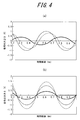
- the transmission speed of the sound detected by the microphone unit 62 is delayed by 0.2 ms with respect to the transmission speed of the vibration detected by the vibration detection element 56
- the combined output of the two sine wave vibrations is shown in FIG. As shown in (a).
- the combined output when there is no difference between the transmission speeds of both is as shown in FIG. 4B, and an amplitude peak or dip appears at a timing that does not occur originally.
- the thick line indicates the vibration detection waveform at the vibration detection element 56
- the thin line indicates the sound pressure detection waveform at the microphone unit 62
- the broken line indicates the combined output waveform. .
- the phase of the detection signal by the vibration detection element 56 that is the output of the equalizer 421 is adjusted within a predetermined range by the variable delay circuit 431 according to the measurement frequency range of the acoustic device 1 to be measured.
- the variable delay circuit 431 uses the vibration detection element 56 in a range of about ⁇ 10 ms (corresponding to ⁇ 100 Hz) and at least smaller than 0.1 ms (corresponding to 10 kHz). Adjust the phase of the detection signal. Even in the case of the human ear, a phase shift occurs between the human body vibration sound and the air conduction sound. Therefore, the phase adjustment by the variable delay circuit 431 matches the phases of the detection signals of both the vibration detection element 56 and the microphone unit 62. It does not mean that, but it means that the phase of both is matched to the actual audibility of the ear.
- the output of the phase adjustment unit 430 is supplied to the output synthesis unit 440.
- the output synthesizing unit 440 synthesizes the detection signal from the vibration detecting element 56 phase-adjusted by the variable delay circuit 431 and the detection signal from the microphone unit 62 that has passed through the phase adjusting unit 430.
- the vibration amount and sound pressure transmitted by the vibration of the acoustic device 1 to be measured, that is, the sensory sound pressure obtained by synthesizing the human body vibration sound and the air conduction sound by approximating the human body.
- the synthesized output of the output synthesis unit 440 is input to the frequency analysis unit 450.
- the frequency analysis unit 450 includes an FFT (Fast Fourier Transform) 451 that performs frequency analysis on the synthesized output from the output synthesis unit 440.
- FFT Fast Fourier Transform
- the frequency analysis unit 450 outputs a signal before being synthesized by the output synthesis unit 440, that is, a detection signal from the vibration detection element 56 that has passed through the phase adjustment unit 430 and a detection signal from the microphone unit 62.
- FFT 452 and 453 for frequency analysis are provided. Thereby, power spectrum data corresponding to the human body vibration sound (vib) is obtained from the FFT 452, and power spectrum data corresponding to the air conduction sound (air) is obtained from the FFT 453.
- the analysis point of a frequency component is set according to the measurement frequency range of the audio equipment 1. For example, when the measurement frequency range of the acoustic device 1 is 100 Hz to 10 kHz, the frequency component of each point obtained by dividing the interval in the logarithmic graph of the measurement frequency range into 100 to 200 is analyzed.
- the outputs of FFTs 451 to 453 are stored in the storage unit 460.
- the storage unit 460 has a capacity larger than a double buffer capable of holding a plurality of pieces of analysis data (power spectrum data) obtained by the FFTs 451 to 453. And it can comprise so that the newest data can always be transmitted at the data transmission request timing from PC500 mentioned later.
- the signal processing control unit 470 is connected to the PC 500 via an interface connection cable 510 such as a USB, RS-232C, SCSI, or PC card. Based on a command from the PC 500, the operation of each unit of the signal processing unit 400 is controlled.
- the signal processing unit 400 can be configured as software executed on any suitable processor such as a CPU (Central Processing Unit), or can be configured by a DSP (Digital Signal Processor).
- the PC 500 has an evaluation application for the acoustic device 1 by the measurement system 10.
- the evaluation application is downloaded via, for example, a CD-ROM or a network.
- the PC 500 displays an application screen based on the evaluation application on the display unit 520.
- a command is transmitted to the signal processing unit 400 based on information input via the application screen.
- the PC 500 receives a command response and data from the signal processing unit 400, performs predetermined processing based on the received data, and displays the measurement result on the application screen. Further, if necessary, the measurement result is output to the printer 600 and printed.
- the sensitivity adjustment unit 300 and the signal processing unit 400 are mounted on the base 30 of the audio equipment mounting unit 20, for example, and the PC 500 and the printer 600 are installed away from the base 30 to perform signal processing.
- the unit 400 and the PC 500 can be connected via the connection cable 510.
- FIG. 5 is a diagram illustrating an example of an application screen displayed on the display unit 520.
- the application screen 521 shown in FIG. 5 includes a “Calibration” icon 522, a “Measure Start” icon 523, a “Measure Stop” icon 524, a measurement result display area 525, a measurement range change icon 526, a measurement result display selection area 527, and a file icon. 528, a measurement type icon 529, and a help icon 530.
- a “Calibration” icon 522 includes a “Calibration” icon 522, a “Measure Start” icon 523, a “Measure Stop” icon 524, a measurement result display area 525, a measurement range change icon 526, a measurement result display selection area 527, and a file icon. 528, a measurement type icon 529, and a help icon 530.
- “Calibration” icon 522 calibrates an error in sensitivity of vibration detecting element 56 and microphone unit 62.
- a standard machine is set in the holding unit 70 and applied to the standard position of the ear mold unit 50.
- the standard machine is vibrated in a predetermined vibration mode (for example, pure tone or multisign)
- the power spectrum data of the detection signal by the vibration detection element 56 and the power spectrum data of the detection signal by the microphone unit 62 correspond to each other.
- the sensitivity of the vibration detecting element 56 and the microphone unit 62 is adjusted by the variable gain amplifier circuits 301 and 302 so as to be in the normal error range.
- the “Measure Start” icon 523 transmits a measurement start command to the signal processing unit 400 and continues to receive data until the measurement is completed.
- the “Measure Stop” icon 524 transmits a measurement end command to the signal processing unit 400 and ends data reception.
- the measurement result display area 525 the measurement result corresponding to the measurement mode selected by the measurement type icon 529 based on the received data is displayed.
- FIG. 5 exemplifies a case where the measurement results of the power spectrum of vib (human body vibration sound), air (air conduction), and air + vib (sensory sound pressure) in the power spectrum measurement mode are displayed in the measurement result display area 525. Yes.
- the measurement range change icon 526 shifts the measurement range width of the power spectrum displayed in the measurement result display area 525 up and down in units of 10 dB and transmits a measurement range change command to the signal processing unit 400. Thereby, the signal processing unit 400 changes the A / D conversion ranges of the A / D conversion circuits 411 and 412 according to the measurement range change command.
- the measurement result display selection area 527 displays the type of power spectrum that can be displayed in the measurement result display area 525 and its selection box, as well as the current value (Now) of the power spectrum, the maximum value during measurement (Max), and the measurement in progress.
- the average value (Average) display area and its selection box are displayed, and the power spectrum and the high-frequency distortion factor are displayed in the corresponding area for the information selected in the selection box.
- the file icon 528 prints an application screen being displayed, for example, and outputs a measurement result in a format such as CSV or EXCEL.
- a measurement type icon 529 switches measurement modes such as a power spectrum measurement mode and a high-frequency distortion factor measurement mode. Note that the high-frequency distortion rate displayed in the measurement result display selection area 527 can be calculated by the PC 500 based on the measurement data in the signal processing unit 400 in the high-frequency distortion rate measurement mode.
- the help icon 530 displays help on how to use the measurement system 10.
- the measurement system 10 analyzes the frequency component of the combined output of the vibration detection element 56 and the microphone unit 62 while vibrating the vibration body of the acoustic apparatus 1 to be measured by, for example, a piezoelectric element. Evaluate 1.
- the piezoelectric element constituting the vibrating body can be driven by a multi-drive signal wave obtained by synthesizing drive signals every 100 Hz in a predetermined measurement frequency range, for example, the above-mentioned range of 100 Hz to 10 kHz.
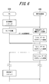
- the PC 500 transmits a measurement start command to the signal processing unit 400.
- the signal processing unit 400 receives the measurement start command, the signal processing unit 400 performs the measurement of the acoustic device 1.
- the signal processing unit 400 adjusts the sensitivity of the outputs of the vibration detection element 56 and the microphone unit 62 by the sensitivity adjustment unit 300, converts the output to a digital signal by the A / D conversion unit 410, and further converts the frequency characteristic adjustment unit.
- the phase is adjusted by the phase adjustment unit 430 and synthesized by the output synthesis unit 440.
- the signal processing unit 400 performs frequency analysis on the combined output from the output combining unit 440 using the FFT 451 of the frequency analyzing unit 450 and stores 100 points of power spectrum data, that is, “air + vib” data in the storage unit 460.
- the signal processing unit 400 frequency-analyzes the detection signal from the vibration detection element 56 phase-adjusted by the variable delay circuit 431 of the phase adjustment unit 430 using the FFT 452, and stores 100-point power spectrum data, that is, “vib” data. Store in the unit 460.
- the signal processing unit 400 performs frequency analysis on the detection signal from the microphone unit 62 that has passed through the phase adjustment unit 430 using the FFT 453, and stores 100-point power spectrum data, that is, “air” data in the storage unit 460.
- the signal processing unit 400 repeats the FFT processing by the FFTs 451 to 453 at a predetermined timing, and stores the result in the storage unit 460.
- the storage unit 460 stores the data from the FFTs 451 to 453 while sequentially updating them, and always holds the latest data.
- the PC 500 starts a timer at a predetermined timing, and transmits a data transmission request command to the signal processing unit 400.
- the signal processing unit 400 receives the data transmission request from the PC 500, the latest “vib” data, “air” data, and “air + vib” data stored in the storage unit 460 are sequentially transmitted to the PC 500. To do.
- the PC 500 transmits a data transmission request command to the signal processing unit 400 for each set time of the timer until the measurement end command is transmitted to the signal processing unit 400, and the latest “vib” data. , “Air” data, and “air + vib” data. Each time the PC 500 acquires data from the signal processing unit 400, the PC 500 displays the measurement result on the application screen 521 of FIG. 5 based on the acquired data.
- the PC 500 transmits a measurement end command to the signal processing unit 400. Thereby, the PC 500 and the signal processing unit 400 end the measurement operation.
- the measurement result of the acoustic device 1 is output from the printer 600 as necessary during or after the measurement of the acoustic device 1.
- FIG. 7 is a diagram showing the power spectrum of the vibration amount measured by the conventional measurement method for the acoustic device 1 to be measured which is the same as FIG.
- the thick line indicates the power spectrum measured by pressing the vibration pickup against the vibration body to be measured
- the thin line indicates the power spectrum measured via the artificial mastoid.
- the power spectrum corresponding to the human body vibration sound component measured based on the output of the vibration detecting element 56 is greater than that of the conventional artificial mastoid method. It is larger than the power spectrum by the mastoid method.
- the frequency measurement band exceeds a certain value and becomes smaller than the direct measurement method. That is, the power spectrum corresponding to the human body vibration sound component measured according to the present embodiment is a weighted characteristic of vibration transmission of the human ear.
- the microphone unit 62 measures the sound pressure via the ear mold unit 50. Therefore, the power spectrum corresponding to the air conduction component measured based on the output of the microphone unit 62 is the sound pressure corresponding to the air conduction component heard directly through the eardrum when the air vibrates due to the vibration of the acoustic device 1.
- the sound pressure corresponding to the air conduction component for listening to the sound generated in the ear itself through the eardrum due to the vibration of the acoustic device 1 due to the vibration of the acoustic device 1 is synthesized. That is, the power spectrum corresponding to the air conduction component measured by the present embodiment is weighted with the characteristics of sound pressure transmission of the human ear.
- the phase of the output corresponding to the human body vibration sound component from the vibration detection element 56 and the output corresponding to the air conduction component from the microphone unit 62 is adjusted by the phase adjustment unit 430.
- both outputs are synthesized by the output synthesis unit 440 and subjected to frequency analysis by the frequency analysis unit 450. Therefore, it is possible to measure a body sensation sound pressure obtained by synthesizing the vibration amount and the sound pressure transmitted to the human body due to the vibration of the acoustic device 1 to be measured by approximating the human body.
- the acoustic device 1 can be evaluated with high accuracy, and the reliability of the measurement system 10 can be improved.
- the frequency analysis unit 450 performs frequency analysis independently on the output corresponding to the human body vibration sound component from the vibration detection element 56 and the output corresponding to the air conduction component from the microphone unit 62.
- the acoustic device 1 can be evaluated in more detail.
- the sensitivity adjustment unit 300 adjusts the sensitivity of the vibration detection element 56 and the microphone unit 62, it is possible to measure the body sensation sound pressure according to the age and the like. Therefore, the acoustic device 1 can be evaluated according to the function of the individual ear.
- the frequency characteristic adjustment unit 420 is configured so that the frequency characteristic of the output corresponding to the human body vibration sound component from the vibration detection element 56 and the output corresponding to the air conduction component from the microphone unit 62 can be adjusted independently.
- the acoustic device 1 can be evaluated with higher accuracy according to the function of the individual ear.
- the acoustic device 1 to be measured can change the pressing force on the ear mold portion 50 and can change the contact posture, the acoustic device 1 can be evaluated in various modes.
- FIG. 8 is a block diagram of the audio device 1 according to an embodiment of the present invention.
- the acoustic device 1 is, for example, a hearing aid 1, and includes a vibrating body 10a, a microphone unit 20a, a control unit 30a, a volume / sound quality adjustment interface unit 40a, and a storage unit 50a.
- the vibrating body 10a includes a bending piezoelectric element 101a and a panel 102a that is bent and vibrated directly by the piezoelectric element 101a.
- FIG. 9A schematically shows a state in which the panel 102a is bent by the piezoelectric element 101a.
- the vibrating body 10a allows the user to hear air conduction sound and human body vibration sound due to vibration.
- FIG. 9B shows the panel 102a by the piezoelectric element 101a at the end (the left end in FIG. 9A), the center, and the other end (the right end in FIG. 9A) of the panel 102a.
- the amount of displacement in the z direction when bent is shown. As shown in FIG. 9B, it can be seen that the amount of displacement in the z direction differs depending on the position of the panel 102a, and therefore the panel 102a is wavy.
- the piezoelectric element 101a is an element that expands or contracts or bends (curves) in accordance with an electromechanical coupling coefficient of a constituent material by applying an electric signal (voltage).
- the piezoelectric element 101a may be a unimorph, bimorph, or multilayer piezoelectric element.
- the stacked piezoelectric element includes a stacked unimorph element in which unimorphs are stacked (for example, 16 layers or 24 layers), or a stacked bimorph element in which bimorphs are stacked (for example, 16 layers or 24 layers are stacked).
- the laminated piezoelectric element is composed of a laminated structure of a plurality of dielectric layers made of, for example, PZT (lead zirconate titanate) and electrode layers arranged between the plurality of dielectric layers.
- a unimorph expands and contracts when an electric signal (voltage) is applied, and a bimorph bends when an electric signal (voltage) is applied.
- the surface of the piezoelectric element 101a that contacts the panel 102a (hereinafter referred to as a main surface) has a width of 4.0 mm and a length of 17.5 mm. In the following description, it is assumed that the main surface of the piezoelectric element 101a has a width of 4.0 mm and a length of 17.5 mm.
- the panel 102a is formed of synthetic resin such as glass or acrylic, for example.
- the shape of the panel 102a is preferably a plate shape, and the following description will be made assuming that the shape of the panel 102a is a plate shape.
- the microphone unit 20a collects the sound from the sound source, specifically the sound that has arrived at the user's ear.
- the control unit 30a performs various controls related to the hearing aid 1.
- the control unit 30a applies a predetermined electrical signal (voltage corresponding to the sound signal) to the piezoelectric element 101a.
- the analog-digital conversion unit 31 converts the sound signal collected by the microphone unit 20a into a digital signal.
- the signal processing unit 32 outputs a digital signal for driving the vibrating body 10a based on the information related to the volume and sound quality by the volume / sound quality adjustment interface unit 40a and the information stored in the storage unit 50a.
- the digital-analog conversion unit 33a converts the digital signal into an analog electric signal, amplifies it by the piezoelectric amplifier 34, and applies the electric signal to the piezoelectric element 101a.
- the voltage applied to the piezoelectric element 101a by the control unit 30a is, for example, ⁇ 15V, which is higher than ⁇ 5V, which is an applied voltage of a so-called panel speaker for the purpose of conducting sound by air conduction sound instead of human body vibration sound. It may be. Thereby, sufficient vibration can be generated in the panel 102a and a human body vibration sound can be generated through a part of the user's body. Note that how much applied voltage is used can be appropriately adjusted according to the fixing strength of the panel 102a or the performance of the piezoelectric element 101a.
- the control unit 30a applies an electrical signal to the piezoelectric element 101a, the piezoelectric element 101a expands or contracts or bends in the longitudinal direction.
- the panel 102a to which the piezoelectric element 101a is attached is deformed in accordance with expansion / contraction or bending of the piezoelectric element 101a, and the panel 102a vibrates.
- the panel 102a is curved by expansion / contraction or bending of the piezoelectric element 101a.
- the panel 102a is bent directly by the piezoelectric element 101a.
- “the panel 102a is directly bent by the piezoelectric element 101a” means that the inertial force of the piezoelectric actuator configured by arranging the piezoelectric element 101a in the casing as employed in a conventional panel speaker. This is different from the phenomenon in which a specific region of the panel 102a is vibrated and the panel 102a is deformed.
- the panel 102a is directly bent by the piezoelectric element 101a means that expansion or contraction (bending) of the piezoelectric element 101a directly bends the panel 102a via the bonding member.
- the panel 102a since the panel 102a vibrates, the panel 102a generates air conduction sound and, when the user contacts the tragus, generates human body vibration sound via the tragus.
- the panel 102a vibrates with the vicinity of both ends of the panel 102a as a node and the center as a belly, and the vicinity of the center of the panel 102a is brought into contact with the tragus or the antitragus. By doing in this way, the vibration of the panel 102a can be efficiently transmitted to the tragus or the tragus.
- FIG. 10 is a schematic diagram showing a configuration of the hearing aid 1 according to the embodiment of the present invention.
- the vibrating body 10a includes a pressing member 11a and a pressing member mounting portion 12a.
- the pressing member 11a is attached to the vibrating body 10a.
- the vibrating body 10a is brought into contact with a part of the external auditory canal facing the tragus, for example, in the vicinity of the tragus. Press on the contact point of the pearl.
- the position where the vibrating body 10a contacts the user's ear may be, for example, tragus, antitragus, concha, or auricle.
- the position in contact with the user's ear is the tragus (the inner wall of the ear canal side of the tragus) will be described.
- the pressing member attaching portion 12a is a member for attaching the pressing member 11a to the vibrating body 10a.
- the pressing member 11a and the mounting portion 12a are shaped to fit each other.
- the pressing member 11a has a concave cut portion 111a
- the attachment portion 12a has a convex shape that fits into the cut portion 111a.
- the pressing member 11a can be attached to and detached from the vibrating body 10a by sliding in the width direction.
- the vibrating body 10a has a thickness (D) of 4 mm and a width (W) of 15 mm or less.
- the gender age is not limited (except for infants and younger), and the vibrating body 10a can be housed in the ear canal of the user's ear.
- the pressing member 11a has three types of sizes (small size, medium size, and large size), and the pressing member 11a is selected according to the size of the user's ear. It attaches to the attachment part 12a of a member.
- the holding portion 60a includes a support portion 61a, an ear hooking portion 62a, and a main body portion 63a, and holds the vibrating body 10a at a position where the vibrating body 10a contacts the user's ear (an inner wall of the ear canal side).
- the end of the support portion 61a is connected to the vibrating body 10a.
- the support portion 61a has a hollow structure, and lead processing to the vibrating body 10a is performed through the hollow structure. Further, the support portion 61a has a rigidity that does not change the angle of the vibrating body 10a.
- the other end of the support 61a is connected to the end of the ear hook 62a.
- the ear hook 62a contacts the outside of the user's pinna and wears the hearing aid 1 on the user's ear.
- the ear hook 62a has a hook shape along the user's pinna so that the hearing aid 1 can be stably attached to the user's ear.
- the other end of the ear hook 62a is connected to the main body 63a.
- the main body 63a includes a microphone unit 20a, a control unit 30a, a volume / sound quality adjustment interface unit 40a, and a storage unit 50a.
- FIG. 11 is a side view of the vibrating body 10a viewed from the thickness direction.
- the vibrating body 10a includes the piezoelectric element 101a and the panel 102a.
- the piezoelectric element 101a has a plate shape.
- the piezoelectric element 101a is joined to the panel 102a by a joining member.
- the joining member is provided between the main surface of the piezoelectric element 101a and the main surface of the panel 102a.
- the joining member may be a non-heating type curable adhesive or a double-sided tape.
- the piezoelectric element 101a other than the joint surface with the panel 102a is covered with the mold 103a.
- a pressing member 11a and a pressing member mounting portion 12a are provided on the upper portion of the mold 103a.
- the surface (main surface) in contact with the ear of the panel 102a has an area that is 0.8 to 10 times the area of the main surface of the piezoelectric element 101a. If the main surface of the panel 102a has an area in the range of 0.8 to 10 times the main surface of the piezoelectric element 101a, the panel 102a can be deformed according to the expansion or contraction or bending of the piezoelectric element 101a, and the contact area with the user's ear is large. Enough can be secured.
- the area of the piezoelectric element and the panel is more preferably 0.8 times to 5 times, for example. Therefore, for example, the size of the main surface of the panel 102a is 10 mm in width and 18 mm in length. In the following description, it is assumed that the main surface of the panel 102a has a width of 10 mm and a length of 18 mm.
- FIG. 12 is a diagram showing a state in which the hearing aid 1 according to one embodiment of the present invention is worn on the user's ear.
- FIG. 12A is a view of the ear as seen from the front
- FIG. 12B is a view of the face as viewed from the side.
- the hearing aid 1 according to the present invention allows the user to hear sound by bringing the vibrating body 10a into contact with the user's tragus or the antitragus from the inside of the user's ear and transmitting the vibration to the tragus or the antitragus. .
- the vibrating body 10a when the vibrating body 10a is embedded in the external auditory canal of the ear when the vibrating body 10a is "in contact with the user's tragus or the antitragus from the inside of the user's ear" It means contacting with a bead or anti-tragus.
- the vibrating body 10a is brought into contact with the user's tragus from the inside of the user's ear.
- the pressing member 11a is in contact with a part of the ear canal facing the tragus.
- the vibrating body 10a has the direction of the arrow 601 through the support portion 61a due to the weight of the holding portion 60a, that is, the weight of the main body portion 63a connected to the end of the ear hook 62a. Pulled on. As shown in FIG. 12 (b), the vibrating body 10a is in contact with the tragus so that the vibrating body 10a is in contact with the user's ear when the vibrating body 10a is pulled (the direction of the arrow 602). ) Power works. That is, due to the weight of the holding portion 60a, a force (pressing force) in a direction in which the vibrating body 10a is brought into contact with the user's ear is generated. In this way, the holding unit 60a generates a pressing force on the vibrating body 10a, and ensures transmission of sound due to the vibration of the vibrating body 10a.
- the vibrating body 10a is pressed against the user's ear with a force of 0.1N to 3N.
- the vibrating body 10a is pressed in the range of 0.1N to 3N, vibrations from the vibrating body 10a are sufficiently transmitted to the ear. If the pressing force is a small force of less than 3N, even if the hearing aid 1 is worn for a long time, the user feels less tired and can maintain comfort during wearing.
- the hearing aid 1 of the present invention does not cause a feeling of being bulky and can maintain comfort when worn.
- FIG. 13 is a schematic view showing transmission of sound from the hearing aid 1 according to one embodiment of the present invention.
- the microphone unit 20a collects sound from the sound source, and the vibrating body 10a lets the user hear the sound collected by the microphone unit 20a by vibration.
- the sound from the sound source arrives directly at the eardrum through the ear canal from the portion not covered by the vibrating body 10a (path I).
- air conduction sound due to vibration of the vibrating body 10a arrives at the eardrum through the ear canal (path II).
- at least the inner wall of the ear canal vibrates due to the vibration of the vibrating body 10a, and air conduction sound (radiation sound of the ear canal) due to the vibration of the ear canal reaches the eardrum (path III).
- human body vibration sound directly arrives at the auditory nerve without passing through the eardrum due to the vibration of the vibrating body 10a (trans IV). A part of the air conduction sound generated from the vibrating body 10a escapes to the outside (path V).
- FIG. 14 shows a schematic diagram of the acoustic characteristics of each route.
- FIG. 14A shows the acoustic characteristics of the sound of the path I
- FIG. 14B shows the acoustic characteristics of the sound of the paths II and III.
- the bass sound escapes through the path V, so that the sound pressure in the bass area is low.
- FIG. 14C shows the acoustic characteristics of longitude IV.
- the human body vibration sound is a low sound, that is, a vibration in a low frequency region, and thus is not easily attenuated, and therefore is more easily transmitted than a high sound. Accordingly, the bass sound is sufficiently transmitted.
- FIG. 14 (c) the human body vibration sound is a low sound, that is, a vibration in a low frequency region, and thus is not easily attenuated, and therefore is more easily transmitted than a high sound. Accordingly, the bass sound is sufficiently transmitted.
- FIG. 14D shows the synthesis of the sound of the path I or IV, that is, the actual acoustic characteristic that the user wearing the hearing aid 1 hears.
- the low sound pressure escapes to the outside in the path V
- the low sound pressure particularly the low sound pressure of 1 kHz or less is ensured by the human body vibration sound in this embodiment. This makes it possible to maintain a sense of volume.
- FIG. 15 shows measured values of frequency characteristics of the hearing aid 1 of the present invention.
- Air is the frequency characteristic of the sound of path II and path III in FIG. 13
- vib is the frequency characteristic of the sound of path IV in FIG.
- Air + vib is a frequency characteristic of the sound obtained by synthesizing the sound of the route II to the route IV.
- Sound from the outside is the frequency characteristic of the sound of path I in FIG.
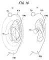
- FIG. 16 is a diagram illustrating a relationship between the vibrating body 10a and the microphone unit 20a of the hearing aid 1 according to the embodiment of the present invention. Since the microphone part 20a is provided in the main body part 63a of the holding part 60a, it is located outside the auricle. FIG. 16A is an example in which the vibrating body 10a is in contact with the user's tragus from the outside of the user's ear. In this case, since the air conduction sound emitted by the vibrating body 10a is not shielded up to the microphone unit 20a, the amount of feedback returning to the microphone unit 20a is large, and howling is facilitated, and the performance (amplification amount) of the hearing aid 1 is increased. Can not raise.
- the vibrating body 10a is brought into contact with the user's tragus from the inside of the user's ear.
- the user's ears mainly tragus and earring legs
- the microphone unit 20a is located between the microphone unit 20a and the vibrating body 10a. Therefore, the sound emitted by the vibrating body 10a is reflected by the user's ear, and the amount of sound directly returning to the microphone unit 20a is less than in the case of FIG. Therefore, howling becomes difficult and the performance of the hearing aid 1 can be improved.
- an outer peripheral portion of the ear such as an earring, an auricular nodule, or an earlobe only needs to be present therebetween.
- a lower leg of the earring, an earring, and the like may be present therebetween.
- the hearing aid 1 of the present invention since the sound of the user is heard by the vibration of the vibrating body 10a, it is possible to secure a low sound pressure by the human body vibration sound and suppress the loss of volume. Since it is not necessary to provide a vent for preventing the bass from escaping, it is possible to suppress impairing comfort during mounting.
- the vibrating body 10a of the acoustic device 1 is pressed against the ear mold portion 50 of the measurement system 10 with a force of 0.05N to 3N.
- the said range is a range where the vibrating body 10a of the audio equipment 1 is pressed by a human ear. More preferably, the vibrating body 10a is pressed against the ear mold portion 50 with a force of 0.1N to 2N. This is because the vibration body 10a of the acoustic device 1 is highly likely to be pressed by a human ear within the range. That is, when the vibrating body 10a is pressed against the ear mold part 50 with a force of 0.1N to 2N, a measurement result that is more suitable for the actual usage mode can be obtained.
- an area (hereinafter referred to as a contact area) in contact with the ear mold part 50 of the measurement system 10 of the vibrating body 10a of the acoustic device 1 is 0.1 cm 2 to 4 cm 2.
- the range of the contact area is a range in which the vibrating body 10a of the acoustic device 1 contacts the human ear. More preferably, the contact area is 0.3 cm 2 to 3 cm 2. This is because there is a high possibility that the vibrating body 10a of the acoustic device 1 is in contact with the human ear within the range. That is, by setting the contact area to 0.3 cm 2 to 3 cm 2, a measurement result that is more suitable for the actual usage mode can be obtained.
- 17 to 19 show the air conduction measured by the measurement system 10 when a fundamental sound of 500 Hz is output in a state where the vibrating body 10a of the acoustic device 1 is in contact with the tragus of the ear mold portion 50 of the measurement system 10.
- the power spectrum of a sound and / or a human body vibration sound is shown.
- FIG. 17 shows the power spectrum of the synthesized sound of air conduction sound and human body vibration sound.
- a power spectrum in which a plurality of overtones appear in addition to the fundamental tone of 500 Hz is measured. Specifically, secondary overtones (1000 Hz) and tertiary overtones (1500 Hz) appear. Further, a plurality of overtones of sixth order or more are measured, and the number of overtones having an S / N (signal-to-noise ratio) of 10 dB or more is counted from the noise floor. When the number of overtones is counted in this way, three or more sixth-order overtones having a volume higher than ⁇ 45 dB with respect to the volume of the fundamental tone are measured.
- S / N signal-to-noise ratio
- the volume exceeding ⁇ 45 dB relative to the fundamental tone means a volume exceeding 45 dB when the fundamental tone is, for example, 90 dB.
- the harmonic over which the S / N (signal-to-noise ratio) is 10 dB or more from the noise floor refers to a harmonic over 35 dB when the noise floor is 25 dB, for example.
- the volume obtained by dividing the volume of the fundamental tone by 2 is, for example, a volume obtained by dividing 90 dB by 2 when the fundamental tone is 90 dB, that is, 45 dB.
- the number of overtones in the synthesized sound is counted on the condition that the sound (air + vib) obtained by synthesizing the vibration component and the air conduction component in the fundamental tone is 75 dB or more.
- the number of overtones in the air conduction sound may be counted on the condition that the air conduction component sound (air) in the fundamental sound is counted when there is an output of 70 dB or more.
- FIG. 18 shows the power spectrum of human body vibration sound.
- 500 Hz fundamental tone is measured, harmonics hardly appear. That is, unlike FIG. 17, the measurement result of FIG. 18 does not measure three or more sixth-order harmonics having a measured value that exceeds ⁇ 50 dB with respect to the measured value of the fundamental tone.
- three or more harmonics of 6th order or higher exceeding the value obtained by dividing the measured value of the fundamental tone by 2 are not measured.
- the human body vibration sound referred to here is not vibration energy (conceptually, at least III and IV in FIG. 13) itself generated by the panel 102a. That is, the vibration detection element 56 measures the vibration energy generated by the panel 102a except for the energy (conceptually, III in FIG. 13) converted into an air conduction component in the external ear canal portion 52 and the like. Component (conceptually IV in FIG. 13). Thereby, it turns out that the person has not heard sufficient overtone depending on the vibration component.
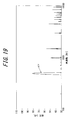
- FIG. 19 shows the power spectrum of the air conduction sound.
- a power spectrum in which a plurality of overtones appear in addition to the fundamental tone of 500 Hz is measured. Specifically, secondary overtones (1000 Hz) and tertiary overtones (1500 Hz) appear. Furthermore, a plurality of overtones of the sixth order or more are measured, and three or more overtones of the sixth order or more having a volume higher than ⁇ 45 dB with respect to the volume of the fundamental tone are measured. In FIG. 17, three or more harmonics of 6th order or higher exceeding the volume obtained by dividing the volume of the fundamental tone by 2 are measured.
- the air conduction sound here is the air conduction sound measured by the microphone unit 62, the component generated as the air conduction sound from the panel 102a and the air conduction sound component converted from the inner wall of the external ear canal into the air conduction sound.
- the volume is the sum of (II and III in FIG. 13).
- FIGS. 20 and 21 when a fundamental sound of 500 Hz is output with AFTERSHOOKZ (registered trademark), which is a conventional bone conduction headphone, and a bone conduction sound collector ear, in contact with the tragus, a measurement system 10 shows the measurement results of the power spectrum of air conduction sound and / or human body vibration sound measured by No. 10.
- the sixth or higher harmonics are hardly generated in the predetermined count condition described above. Specifically, three or more sixth-order harmonics having a volume higher than ⁇ 45 dB with respect to the volume of the fundamental tone are not measured. In addition, three or more harmonics of 6th order or higher exceeding the value obtained by dividing the measured value of the fundamental tone by 2 are not measured.
- FIGS. 22 and 23 show measurement results when the size of the main surface of the panel 102a of the acoustic device 1 is changed from a width of 10 mm and a length of 18 mm (referred to as “10 ⁇ 18”). 22 and 23, measurement results of a plurality of patterns from a width of 15 mm and a length of 18 mm (referred to as “15 ⁇ 18”) to a width of 8 mm and a length of 18 mm (referred to as “8 ⁇ 18”) are shown. Show. As shown in FIG. 22, it can be seen that in any case, a plurality of sixth-order or higher harmonics are generated in the predetermined count condition described above. As shown in FIG.
- three or more sixth-order harmonics having a volume higher than ⁇ 45 dB with respect to the volume of the fundamental tone are measured regardless of the size of the main surface of the panel 102a.
- the volume of the fundamental tone is 79.8 dB.
- the volumes of the 6th, 9th, and 12th harmonics are 38.9 dB, 44.6 dB, and 43.0 dB, respectively.
- ⁇ 45 dB with respect to the volume of the fundamental tone that is, a value exceeding 34.8 dB
- three or more overtones of 6th order or more having a volume greater than ⁇ 45 dB with respect to the volume of the fundamental tone are measured.
- the 7th, 9th, and 11th harmonics are 42.3 dB, 44.6 dB, and 42.0 dB, respectively. Therefore, three or more sixth or higher harmonics exceeding the volume obtained by dividing the volume of the fundamental tone by 2 are measured. It is further preferable if the number of overtones counted under the predetermined count condition described above is four or more.
- the number of overtones counted under the above-described predetermined count condition is 5 or more.
- the frequency band in which the overtones are generated is preferably within the audible range.
- the above-described sixth or higher harmonics are three or more within a range of 3 kHz to 10 kHz with respect to a fundamental tone of 300 Hz to 1 kHz.
- the above-mentioned sixth or higher harmonics are four or more in the range of 3 kHz to 10 kHz with respect to the fundamental tone of 300 Hz to 1 kHz.
- there are five or more harmonics of the above-mentioned sixth order within 3 kHz to 10 kHz with respect to the fundamental tone of 300 Hz to 1 kHz.
- the sixth or higher harmonics are generated at a high volume level. Therefore, according to the acoustic device 1 according to the present invention, a bright and well passing sound is perceived.
- the sound reproducing device is the hearing aid 1
- the present invention is not limited to this.
- the sound reproducing device may be a headphone or an earphone.
- the microphone unit 20a is not provided.
- sound based on the music data stored in the internal memory of the sound playback device or sound based on the music data stored in the external server or the like may be played back by the sound playback device via the network. Good.
- the measurement is performed in a state where the vibrating body 10a of the acoustic device 1 is in contact with the tragus of the ear mold part 50 of the measurement system 10, but the present invention is not limited to this, and any of the ear mold parts 50 of the measurement system 10 You may make it contact with the site
- the vibrating body 10a may be brought into contact with the pinna of the ear mold portion 50 of the measurement system 10.
- the fundamental tone generated by the acoustic device 1 is set to 500 Hz, but is not limited thereto.
- a sound having an arbitrary predetermined frequency in a range of 300 Hz or more and 1000 Hz or less, such as 400 Hz or 800 Hz, may be used as the fundamental tone.
- the second embodiment is different from the first embodiment in the configuration of the acoustic device 1.
- Other configurations are the same as those of the first embodiment.
- An example in which the acoustic device 1 is the hearing aid 1 as in the first embodiment will be described.
- the same components as those in the first embodiment are denoted by the same reference numerals and description thereof is omitted.
- FIG. 24 is a schematic diagram showing the configuration of the hearing aid 1 according to an embodiment of the present invention.
- the vibrating body 10a is brought into contact with the user's tragus from the outside of the user's ear. Therefore, the holding part 60b is provided.
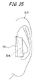
- FIG. 25 shows a portion where the vibrating body 10a is in contact with the tragus from a different angle.
- the portion to be in contact with the tragus is provided with a concave portion 104b to be described later, so that the vibrating body 10a can vibrate without being greatly crushed.
- a sufficient contact area between the body 10a and the tragus can be ensured.
- the position of contact with the user's ear is the tragus will be described.
- the holding part 60b includes a support part 61b, an ear hooking part 62b, and a main body part 63a, and the vibrating body 10a is placed at a position (a tragus) where the vibrating body 10a contacts the user's ear. Hold.
- An end portion of the support portion 61b is connected to the vibrating body 10a.
- the support portion 61b has a hollow structure, and lead processing to the vibrating body 10a is performed through the hollow structure. Further, the support portion 61b has such a rigidity that the angle of the vibrating body 10a does not change.
- the other end of the support 61b is connected to the end of the ear hook 62b.
- the ear hook 62b contacts the outside of the user's pinna and wears the hearing aid 1 on the user's ear.
- the ear hook 62b has a hook shape along the user's pinna so that the hearing aid 1 can be stably attached to the user's ear.
- the other end of the ear hook 62b is connected to the main body 63a.
- the main body 63a includes a microphone unit 20a, a control unit 30a, a volume / sound quality adjustment interface unit 40a, and a storage unit 50a.
- FIG. 26 is a side view of the vibrating body 10a viewed from the thickness direction.
- the vibrating body 10a includes the piezoelectric element 101a and the panel 102a.
- the piezoelectric element 101a has a plate shape.
- the piezoelectric element 101a is joined to the panel 102a by a joining member.
- the joining member is provided between the main surface of the piezoelectric element 101a and the main surface of the panel 102a.
- the joining member may be a non-heating type curable adhesive or a double-sided tape.
- the piezoelectric element 101a is covered with a mold 103a except for the joint surface with the panel 102a.
- the main surface of the panel 102a includes a recess 104b.
- the recess 104b is a portion where the central portion of the panel 102a is recessed. Since the tragus protrudes here, when contacting the plane, it is necessary to obtain a contact area by largely crushing the tragus.
- the hearing aid 1 according to the present invention includes the concave portion 104b, and the concave portion 104b is brought into contact with the tragus, so that the contact area can be obtained without greatly crushing the tragus. Since it is not necessary to largely crush the tragus, the holding portion 60b may have a simple structure, and since the tragus is not largely crushed, the comfort of the user wearing the hearing aid 1 can be maintained.
- the panel 102a of the vibrating body 10a is pressed against the user's ear with a force of 0.1N to 3N.
- the vibration by the panel 102a is sufficiently transmitted to the ear. If the pressing force is a small force of less than 3N, even if the hearing aid 1 is worn for a long time, the user feels less tired and can maintain comfort during wearing.
- the recess 104b of the panel 102a has a portion that contacts the user's ear (eg, tragus) and a portion that does not contact. Since there is a portion of the panel 102a that does not contact the user's ear, air conduction sound may be generated from the portion.
- the user's ear eg, tragus
- air conduction sound may be generated from the portion.
- the main surface of the panel 102a has an area that is 0.8 to 10 times the area of the main surface of the piezoelectric element 101a. If the main surface of the panel 102a has an area in the range of 0.8 to 10 times the main surface of the piezoelectric element 101a, the panel 102a can be deformed according to the expansion or contraction or bending of the piezoelectric element 101a, and the contact area with the user's ear is large. Enough can be secured.
- the area of the piezoelectric element and the panel is more preferably 0.8 to 5 times, for example.
- FIG. 27 shows measured values of frequency characteristics of the hearing aid 1 of the present invention.
- Air is the frequency characteristic of the sound of path II and path III in FIG. 13
- vib is the frequency characteristic of the sound of path IV in FIG.
- Air + vib is a frequency characteristic of the sound obtained by synthesizing the sound of the route II to the route IV.
- FIG. 28 shows actual measurement values when the projections 105b are provided on the panel 102a instead of the recesses 104b (FIG. 28 (a)).
- Air is the frequency characteristic of the sound of path II and path III in FIG. 13
- vib is the frequency characteristic of the sound of path IV in FIG.
- Air + vib is a frequency characteristic of the sound obtained by synthesizing the sound of the route II to the route IV.
- FIG. 29 is a diagram illustrating frequency characteristics of “air + vib” when the panel 102a includes the concave portion 104b and the convex portion 105b. As shown in FIG. 29, the configuration in which the panel 102a includes the recess 104b has a higher sound pressure and excellent acoustic characteristics in many frequency regions.
- the acoustic device 1 (hearing aid 1) according to the second embodiment is measured by the measurement system 10, as in the case of the acoustic device according to the first embodiment, with respect to the volume of the fundamental tone with respect to the air conduction sound, Three or more sixth or higher harmonics having a volume higher than ⁇ 45 dB are measured. Also, three or more harmonics of 6th order or higher exceeding the volume obtained by dividing the volume of the fundamental tone by 2 are measured. As for the human body vibration sound, as in the acoustic device according to the first embodiment, three or more harmonics of 6th order or higher having a measurement value exceeding ⁇ 45 dB with respect to the measurement value of the fundamental sound are not measured.
- the acoustic device 1 according to the second embodiment also has three or more sixth-order or higher harmonics having a volume higher than ⁇ 45 dB with respect to the volume of the fundamental tone with respect to the synthesized sound of the air conduction sound and the human body vibration sound. It is measured. Also, three or more harmonics of 6th order or higher exceeding the volume obtained by dividing the volume of the fundamental tone by 2 are measured.
- the third embodiment is different from the first embodiment and the second embodiment in the configuration of the measurement system 10.
- Other configurations are the same as those of the first embodiment or the second embodiment.
- the same components as those in the first embodiment or the second embodiment are denoted by the same reference numerals, and description thereof is omitted.
- FIG. 30 is a diagram showing a schematic configuration of a main part of a measurement system according to the third embodiment of the present invention.
- the measurement system 110 according to the present embodiment is different from the acoustic device mounting unit 20 in the first embodiment in the configuration of the acoustic device mounting unit 120, and the other configurations are the same as those in the first embodiment. Therefore, in FIG. 24, illustration of the measurement part 200 shown in 1st Embodiment is abbreviate
- the acoustic device mounting unit 120 includes a human head model 130 and a holding unit 150 that holds the acoustic device 1 to be measured.
- the head model 130 is made of, for example, HATS or KEMAR.
- the artificial ear 131 of the head model 130 is detachable from the head model 130.
- the artificial ear 131 constitutes an ear mold part, and as shown in a side view removed from the head model 130 in FIG. 31A, the artificial auricle similar to the ear mold part 50 of the first embodiment is used.
- 132 and an artificial external ear canal part 134 coupled to the artificial auricle 132 and having an artificial external ear canal 133 formed thereon.
- a vibration detection unit 135 including a vibration detection element is arranged around the opening of the artificial external ear canal 133, similarly to the ear mold unit 50 of the first embodiment.
- a sound pressure measuring unit 136 having a microphone at the center is arranged at the mounting portion of the artificial ear 131 of the head model 130 as shown in a side view with the artificial ear 131 removed in FIG. Yes.
- the sound pressure measuring unit 136 is arranged so as to measure the sound pressure of the sound propagated through the artificial external ear canal 133 of the artificial ear 131 when the artificial ear 131 is attached to the head model 130.
- the sound pressure measurement unit 136 may be arranged on the artificial ear 131 side in the same manner as the ear mold unit 50 of the first embodiment.
- the vibration detection element constituting the vibration detection unit 135 and the microphone constituting the sound pressure measurement unit 136 are connected to the measurement unit in the same manner as in the first embodiment.
- the holding unit 150 is detachably attached to the head model 130, and includes a head fixing unit 151 to the head model 130, a support unit 152 that supports the acoustic device 1 to be measured, and a head fixing unit 151. And a multi-joint arm portion 153 that couples the support portion 152.
- the holding unit 150 can adjust the pressing force and the contact posture with respect to the artificial ear 131 of the acoustic device 1 supported by the support unit 152 through the articulated arm unit 153 in the same manner as the holding unit 70 of the first embodiment. It is configured.
- the measurement system 110 According to the measurement system 110 according to the present embodiment, a measurement result similar to that of the measurement system 10 according to the first embodiment can be obtained.
- the acoustic device 1 since the acoustic device 1 is evaluated by detachably attaching the artificial ear 131 for vibration detection to the human head model 130, an actual usage mode in which the influence of the head is taken into consideration. This makes it possible to evaluate more appropriately.
- each means, each member, etc. can be rearranged so that there is no logical contradiction, and it is possible to combine or divide a plurality of means, members, etc. into one. .
- Audio equipment (Hearing aid) DESCRIPTION OF SYMBOLS 10,110 Measurement system 20 Acoustic equipment mounting part 30 Base 31 Analog digital conversion part 32 Signal processing part 33 Digital analog conversion part 34 Piezoelectric amplifier 50 Ear mold part 51 Artificial auricle 52 Artificial ear canal part 53 Artificial ear canal part 54 Support member 55 Vibration Measurement unit 56 Vibration detection element 60 Sound pressure measurement unit 61 Tube member 62 Microphone unit 70 Holding unit 71 Support unit 72 Arm unit 73 Movement adjustment unit 10a Vibration body 11a Pushing member 12a Mounting unit 20a Microphone unit 30a Control unit 40a Volume / sound quality adjustment Interface part 50a Storage part 60a, 60b Holding part 61a, 61b Support part 62a, 62b Ear hook part 63a Main body part 101a Piezoelectric element 102a Panel 103a Mold 104b Recessed part 105b Convex part 111a Cut part 120 Acoustic equipment mounting part 130 Head model Type 131 Artificial ear 132 Artificial pinna 132 Artificial pinna
Landscapes
- Health & Medical Sciences (AREA)
- General Health & Medical Sciences (AREA)
- Otolaryngology (AREA)
- Physics & Mathematics (AREA)
- Engineering & Computer Science (AREA)
- Acoustics & Sound (AREA)
- Signal Processing (AREA)
- Neurosurgery (AREA)
- Details Of Audible-Bandwidth Transducers (AREA)
- Measurement Of Mechanical Vibrations Or Ultrasonic Waves (AREA)
Abstract
La présente invention se rapporte à un dispositif acoustique qui permet de percevoir un son clair et pénétrant. L'invention se rapporte d'autre part à un procédé d'utilisation de ce dispositif acoustique. Le dispositif acoustique (1), qui amène un corps vibrant (10a) en contact avec le pavillon de l'oreille humaine afin de transmettre un son à l'utilisateur via la transmission de vibrations, est caractérisé en ce que, lors de la délivrance en sortie de la tonalité fondamentale d'une fréquence prescrite dans une plage de fréquences audibles dans un état où le dispositif acoustique (1) est amené en contact avec un module en forme d'oreille (50) afin de mesurer un son conduit par l'air au moyen d'un système de mesurage (10) comprenant ledit module en forme d'oreille (50) qui comprend un pavillon d'oreille artificiel (51) et un canal auditif artificiel (53) et avec un module microphone (62) qui mesure le son conduit par l'air dans le canal auditif artificiel (53), trois fréquences de tonalité partielles, ou plus, de la 6ème harmonique, ou plus, sont mesurées, qui ont un volume supérieur à -45 dB par rapport au volume de la tonalité fondamentale.
Priority Applications (3)
| Application Number | Priority Date | Filing Date | Title |
|---|---|---|---|
| US14/893,556 US9807520B2 (en) | 2013-05-29 | 2014-05-21 | Acoustic device and method of using the same |
| CN201480025586.5A CN105210385B (zh) | 2013-05-29 | 2014-05-21 | 声学设备以及使用该声学设备的方法 |
| EP14804390.4A EP3007466A4 (fr) | 2013-05-29 | 2014-05-21 | Dispositif acoustique, et procédé pour son utilisation |
Applications Claiming Priority (2)
| Application Number | Priority Date | Filing Date | Title |
|---|---|---|---|
| JP2013112612A JP5774635B2 (ja) | 2013-05-29 | 2013-05-29 | 音響機器及びその使用方法 |
| JP2013-112612 | 2013-05-29 |
Publications (1)
| Publication Number | Publication Date |
|---|---|
| WO2014192778A1 true WO2014192778A1 (fr) | 2014-12-04 |
Family
ID=51988805
Family Applications (1)
| Application Number | Title | Priority Date | Filing Date |
|---|---|---|---|
| PCT/JP2014/064042 Ceased WO2014192778A1 (fr) | 2013-05-29 | 2014-05-21 | Dispositif acoustique, et procédé pour son utilisation |
Country Status (5)
| Country | Link |
|---|---|
| US (1) | US9807520B2 (fr) |
| EP (1) | EP3007466A4 (fr) |
| JP (1) | JP5774635B2 (fr) |
| CN (1) | CN105210385B (fr) |
| WO (1) | WO2014192778A1 (fr) |
Cited By (1)
| Publication number | Priority date | Publication date | Assignee | Title |
|---|---|---|---|---|
| CN106954152A (zh) * | 2015-08-13 | 2017-07-14 | 深圳市韶音科技有限公司 | 骨传导扬声器 |
Families Citing this family (10)
| Publication number | Priority date | Publication date | Assignee | Title |
|---|---|---|---|---|
| JP6240401B2 (ja) * | 2013-04-25 | 2017-11-29 | 京セラ株式会社 | 音響再生機器及び集音型音響再生機器 |
| JP6174409B2 (ja) * | 2013-07-25 | 2017-08-02 | 京セラ株式会社 | 測定システム |
| JP6352678B2 (ja) * | 2013-08-28 | 2018-07-04 | 京セラ株式会社 | 耳型部、人工頭部及びこれらを用いた測定装置ならびに測定方法 |
| JP2016158212A (ja) * | 2015-02-26 | 2016-09-01 | 京セラ株式会社 | 測定システム及び測定方法 |
| WO2017139891A1 (fr) * | 2016-02-17 | 2017-08-24 | Dalhousie University | Actionneur inertiel piézoélectrique |
| CN111429865A (zh) * | 2020-04-23 | 2020-07-17 | 广州市天谱电器有限公司 | 一种古琴专用主动式压电拾音器 |
| CN114760553B (zh) * | 2021-01-11 | 2026-03-27 | 深圳市韶音科技有限公司 | 一种优化骨传导耳机工作状态的方法 |
| CN118056410A (zh) * | 2021-10-08 | 2024-05-17 | Gn 奥迪欧有限公司 | 用于电声测试的耳朵模型单元和用于执行听力设备的电声测试的方法 |
| EP4415387A3 (fr) | 2021-10-22 | 2024-11-13 | Shenzhen Shokz Co., Ltd. | Écouteurs |
| CN115529527B (zh) * | 2022-11-28 | 2023-04-07 | 东莞市云仕电子有限公司 | 一种挂耳式耳机 |
Citations (9)
| Publication number | Priority date | Publication date | Assignee | Title |
|---|---|---|---|---|
| JP2002315098A (ja) * | 2001-04-16 | 2002-10-25 | Star Micronics Co Ltd | 電気音響変換器 |
| JP2005311415A (ja) * | 2004-04-16 | 2005-11-04 | Nec Tokin Corp | 音響振動発生素子 |
| JP2005348193A (ja) | 2004-06-04 | 2005-12-15 | Nec Tokin Corp | 受話器 |
| JP2007019898A (ja) * | 2005-07-08 | 2007-01-25 | Toshiba Corp | 携帯電話機 |
| JP2007103989A (ja) * | 2005-09-30 | 2007-04-19 | Nec Tokin Corp | 受話装置 |
| JP2007221532A (ja) * | 2006-02-17 | 2007-08-30 | Nec Tokin Corp | 音響振動発生素子 |
| JP2009036995A (ja) * | 2007-08-01 | 2009-02-19 | Seiya Inada | 振動付与装置及び振動付与方法 |
| JP2013078116A (ja) * | 2011-09-13 | 2013-04-25 | Kddi Corp | 音声伝達装置 |
| WO2013172039A1 (fr) * | 2012-05-18 | 2013-11-21 | 京セラ株式会社 | Dispositif de mesure, système de mesure et procédé de mesure |
Family Cites Families (6)
| Publication number | Priority date | Publication date | Assignee | Title |
|---|---|---|---|---|
| US3019307A (en) * | 1960-02-15 | 1962-01-30 | Beltone Hearing Aid Company | Artificial mastoid |
| US3922506A (en) * | 1974-01-03 | 1975-11-25 | Frye G J | Acoustical testing system |
| US3979567A (en) * | 1975-02-18 | 1976-09-07 | Frye G J | Microphone coupler for hearing aid having inverted conical end configuration |
| KR100643311B1 (ko) * | 2005-10-04 | 2006-11-10 | 삼성전자주식회사 | 스테레오 음향 제공 장치 및 방법 |
| SE533047C2 (sv) * | 2009-03-24 | 2010-06-15 | Osseofon Ab | Benledningsvibratorkonstruktion med förbättrad högfrekvensrespons |
| JP5965126B2 (ja) * | 2011-10-18 | 2016-08-03 | 株式会社ファインウェル | 音出力装置 |
-
2013
- 2013-05-29 JP JP2013112612A patent/JP5774635B2/ja not_active Expired - Fee Related
-
2014
- 2014-05-21 CN CN201480025586.5A patent/CN105210385B/zh not_active Expired - Fee Related
- 2014-05-21 WO PCT/JP2014/064042 patent/WO2014192778A1/fr not_active Ceased
- 2014-05-21 US US14/893,556 patent/US9807520B2/en not_active Expired - Fee Related
- 2014-05-21 EP EP14804390.4A patent/EP3007466A4/fr not_active Withdrawn
Patent Citations (9)
| Publication number | Priority date | Publication date | Assignee | Title |
|---|---|---|---|---|
| JP2002315098A (ja) * | 2001-04-16 | 2002-10-25 | Star Micronics Co Ltd | 電気音響変換器 |
| JP2005311415A (ja) * | 2004-04-16 | 2005-11-04 | Nec Tokin Corp | 音響振動発生素子 |
| JP2005348193A (ja) | 2004-06-04 | 2005-12-15 | Nec Tokin Corp | 受話器 |
| JP2007019898A (ja) * | 2005-07-08 | 2007-01-25 | Toshiba Corp | 携帯電話機 |
| JP2007103989A (ja) * | 2005-09-30 | 2007-04-19 | Nec Tokin Corp | 受話装置 |
| JP2007221532A (ja) * | 2006-02-17 | 2007-08-30 | Nec Tokin Corp | 音響振動発生素子 |
| JP2009036995A (ja) * | 2007-08-01 | 2009-02-19 | Seiya Inada | 振動付与装置及び振動付与方法 |
| JP2013078116A (ja) * | 2011-09-13 | 2013-04-25 | Kddi Corp | 音声伝達装置 |
| WO2013172039A1 (fr) * | 2012-05-18 | 2013-11-21 | 京セラ株式会社 | Dispositif de mesure, système de mesure et procédé de mesure |
Non-Patent Citations (1)
| Title |
|---|
| See also references of EP3007466A4 |
Cited By (2)
| Publication number | Priority date | Publication date | Assignee | Title |
|---|---|---|---|---|
| CN106954152A (zh) * | 2015-08-13 | 2017-07-14 | 深圳市韶音科技有限公司 | 骨传导扬声器 |
| CN106954152B (zh) * | 2015-08-13 | 2019-07-19 | 深圳市韶音科技有限公司 | 骨传导扬声器 |
Also Published As
| Publication number | Publication date |
|---|---|
| CN105210385B (zh) | 2019-05-03 |
| US20160134977A1 (en) | 2016-05-12 |
| EP3007466A1 (fr) | 2016-04-13 |
| EP3007466A4 (fr) | 2017-05-17 |
| JP5774635B2 (ja) | 2015-09-09 |
| US9807520B2 (en) | 2017-10-31 |
| JP2014232966A (ja) | 2014-12-11 |
| CN105210385A (zh) | 2015-12-30 |
Similar Documents
| Publication | Publication Date | Title |
|---|---|---|
| JP5774635B2 (ja) | 音響機器及びその使用方法 | |
| EP3016410B1 (fr) | Dispositif de mesure et système de mesure | |
| WO2013172039A1 (fr) | Dispositif de mesure, système de mesure et procédé de mesure | |
| WO2014175466A1 (fr) | Appareil de reproduction acoustique et appareil de reproduction acoustique collecteur de sons | |
| WO2014064924A1 (fr) | Dispositif de détection de vibrations, dispositif de mesure de vibrations, système de mesure et procédé de mesure | |
| WO2015029295A1 (fr) | Modèle d'oreille, tête artificielle et dispositif de mesure les utilisant, et procédé de mesure | |
| JP6234082B2 (ja) | 計測システム | |
| JP6174409B2 (ja) | 測定システム | |
| JP6234039B2 (ja) | 測定装置及び測定方法 | |
| JP5474138B2 (ja) | 測定システム及び測定方法 | |
| JP5474137B2 (ja) | 測定システム及び測定方法 | |
| JP5502166B2 (ja) | 測定装置及び測定方法 | |
| JP6243223B2 (ja) | 測定システム及び測定方法 | |
| JP6250774B2 (ja) | 測定装置 | |
| JP6266249B2 (ja) | 測定システム | |
| JP6234081B2 (ja) | 測定装置 | |
| JP6228737B2 (ja) | 測定システム及び測定方法 | |
| JP6161555B2 (ja) | 測定装置 |
Legal Events
| Date | Code | Title | Description |
|---|---|---|---|
| 121 | Ep: the epo has been informed by wipo that ep was designated in this application |
Ref document number: 14804390 Country of ref document: EP Kind code of ref document: A1 |
|
| WWE | Wipo information: entry into national phase |
Ref document number: 2014804390 Country of ref document: EP |
|
| WWE | Wipo information: entry into national phase |
Ref document number: 14893556 Country of ref document: US |
|
| NENP | Non-entry into the national phase |
Ref country code: DE |