WO2014192933A1 - Unité de réseaux de lentilles empilés et dispositif de capture d'image - Google Patents
Unité de réseaux de lentilles empilés et dispositif de capture d'image Download PDFInfo
- Publication number
- WO2014192933A1 WO2014192933A1 PCT/JP2014/064487 JP2014064487W WO2014192933A1 WO 2014192933 A1 WO2014192933 A1 WO 2014192933A1 JP 2014064487 W JP2014064487 W JP 2014064487W WO 2014192933 A1 WO2014192933 A1 WO 2014192933A1
- Authority
- WO
- WIPO (PCT)
- Prior art keywords
- lens array
- positioning
- lens
- array unit
- portions
- Prior art date
- Legal status (The legal status is an assumption and is not a legal conclusion. Google has not performed a legal analysis and makes no representation as to the accuracy of the status listed.)
- Ceased
Links
Images


Classifications
-
- H—ELECTRICITY
- H10—SEMICONDUCTOR DEVICES; ELECTRIC SOLID-STATE DEVICES NOT OTHERWISE PROVIDED FOR
- H10F—INORGANIC SEMICONDUCTOR DEVICES SENSITIVE TO INFRARED RADIATION, LIGHT, ELECTROMAGNETIC RADIATION OF SHORTER WAVELENGTH OR CORPUSCULAR RADIATION
- H10F39/00—Integrated devices, or assemblies of multiple devices, comprising at least one element covered by group H10F30/00, e.g. radiation detectors comprising photodiode arrays
- H10F39/80—Constructional details of image sensors
- H10F39/804—Containers or encapsulations
-
- G—PHYSICS
- G02—OPTICS
- G02B—OPTICAL ELEMENTS, SYSTEMS OR APPARATUS
- G02B3/00—Simple or compound lenses
- G02B3/0006—Arrays
- G02B3/0037—Arrays characterized by the distribution or form of lenses
- G02B3/0062—Stacked lens arrays, i.e. refractive surfaces arranged in at least two planes, without structurally separate optical elements in-between
-
- G—PHYSICS
- G02—OPTICS
- G02B—OPTICAL ELEMENTS, SYSTEMS OR APPARATUS
- G02B7/00—Mountings, adjusting means, or light-tight connections, for optical elements
- G02B7/02—Mountings, adjusting means, or light-tight connections, for optical elements for lenses
- G02B7/022—Mountings, adjusting means, or light-tight connections, for optical elements for lenses lens and mount having complementary engagement means, e.g. screw/thread
-
- H—ELECTRICITY
- H10—SEMICONDUCTOR DEVICES; ELECTRIC SOLID-STATE DEVICES NOT OTHERWISE PROVIDED FOR
- H10F—INORGANIC SEMICONDUCTOR DEVICES SENSITIVE TO INFRARED RADIATION, LIGHT, ELECTROMAGNETIC RADIATION OF SHORTER WAVELENGTH OR CORPUSCULAR RADIATION
- H10F39/00—Integrated devices, or assemblies of multiple devices, comprising at least one element covered by group H10F30/00, e.g. radiation detectors comprising photodiode arrays
- H10F39/80—Constructional details of image sensors
- H10F39/806—Optical elements or arrangements associated with the image sensors
- H10F39/8063—Microlenses
Definitions
- the present invention relates to a laminated lens array unit for a compound eye optical system in which lens arrays including a plurality of lenses arranged two-dimensionally are stacked, and an imaging device incorporating the lens array unit.
- an optical system called a compound eye optical system that performs final image output by dividing the area of the image sensor, placing an optical system in each area, and processing the resulting image is a demand for thinning.
- a compound eye optical system that performs final image output by dividing the area of the image sensor, placing an optical system in each area, and processing the resulting image is a demand for thinning.
- various compound-eye optical systems have been proposed, but none have proposed a technique that enables high-precision alignment between lenses in order to obtain a high image quality while reducing the thickness.
- each lens array is manufactured by injection molding. Specifically, a gate is provided on the side surface of the lens array, and molten resin is injected from the gate. And after cooling and solidifying the resin material for lenses, the lens array is manufactured by taking out from the mold.
- a lens obtained by joining a plurality of lens arrays while being positioned by a positioning portion provided between constituent lenses, and cutting into individual pieces after joining to obtain a composite lens See Patent Document 2.
- both lens arrays are fitted using a convex portion provided in the first lens array and a concave portion provided in the second lens array.
- the periphery of each optical surface is joined so as to surround and seal a gap formed between the opposing optical surfaces, and finally, the lenses are cut to be separated into individual imaging lenses.
- Patent Document 1 As the uneven portion used for fitting the lens array, a combination of a columnar convex portion and a concave portion formed of a cylindrical recess having the same shape as this, or a rectangular parallelepiped convex portion and this Only a combination with a recess made of a recess having the same shape is illustrated, and sufficient consideration has not been given to ensuring positioning accuracy when an actual assembly is assumed. For this reason, the method of patent document 1 is not suitable for the imaging use like this application in which the assembly precision of 10 micrometers or less is calculated
- Patent Document 2 only the protrusions formed on one lens array and the concave portions formed on the other lens array are provided with vertical wall surfaces, and the lens array stack is actually assembled. Are not fully considered. In other words, if the positioning accuracy is increased by fitting the unevenness, the lens array is stressed at the time of fitting, which may cause various problems similar to those described in Patent Document 1. Further, in Patent Document 2, there is no mention of a molding method such as a gate position, for example, and no special consideration is given to resin flowability and other molding conditions.
- JP 2000-227505 A Japanese Patent Laid-Open No. 2003-329808
- the present invention has been made in view of the above-described background art, and is a multilayer lens array unit that can be assembled with high accuracy while ensuring high optical performance, and can be molded with high accuracy, and an imaging incorporating the same.
- An object is to provide an apparatus.
- each of the laminated lens array units according to the present invention has a quadrangular outline (more specifically, a rectangle including a square) as viewed from the optical axis direction, and is arranged two-dimensionally.
- a first lens array and a second lens array having a plurality of lens elements, and a surrounding region surrounding the plurality of lens elements along an edge of the first lens array and an edge of the second lens array.
- a positioning part, and the positioning part includes a first contact part disposed on the first lens array side and a second contact part disposed on the second lens array side and facing the first contact part.
- the first and second lens arrays with respect to their position along a plane parallel to the rectangular frame corresponding to the edges of the first and second lens arrays and rotation about an axis perpendicular to the plane.
- the relative movement is restricted and the surrounding area is Inside, a first lens array and the second lens array and is separated from one another, at least one of said first and second contact portions have a tapered surface abutting or close to the other.
- the positioning portion is not limited to a continuous portion along the surrounding region, but can be a discrete portion or a set of regions.
- the laminated lens array unit at least one of the first contact portion on the first lens array side and the second contact portion on the second lens array side has a tapered surface that is in contact with or close to the other.
- the first lens array and the second lens array are separated from each other inside the surrounding region. Then, by bringing the first and second contact portions into contact or close to each other, the first and second lens arrays with respect to the position along the plane parallel to the rectangular frame and the rotation about the axis perpendicular to the plane. Regulates relative movement. Accordingly, it is possible to regulate the plane direction necessary for the lens array and the rotation direction about the axis perpendicular to the plane without applying stress to the lens array. Therefore, assembly can be performed with high accuracy while maintaining high optical performance. In addition, since the structure between adjacent lens elements of the lens array can be simplified, molding can be performed with high accuracy, and it becomes easy to secure a wide effective area of the lens elements.
- the positioning portions are provided at least at one or more locations in each side portion constituting the four side portions of the quadrangular frame.
- the positioning unit performs positioning by being in a state of hitting one or more lines or hitting a plurality of points in each side portion.
- the positioning portion is provided at each corner portion constituting the four corner portions of the quadrangular frame.
- the positioning unit positions at least one corner portion in a line-by-line state or a point-by-point state at a plurality of points.
- the positioning unit includes two adjacent corner portions of the four corner portions of the quadrangular frame, and the first, second, and third of the quadrangular frames that form the two corner portions. It is provided in a fourth side portion different from the side portion, and at least one of the positioning portions of the two corner portions and the fourth side portion performs positioning in a line hit state or a point hit state at a plurality of points. .
- the positioning portion includes a third corner portion that is different from one corner portion of the four corner portions of the quadrangular frame and the first and second side portions of the quadrangular frame that form the corner portion. And at least one of the one corner part, the third side part, and the fourth side part is positioned in a line-by-line or multiple-points-pointed state. I do.
- the first and second lens arrays are made of an integral body made of an optical material.
- the gap between the first contact portion and the second contact portion is 10 ⁇ m or less.
- the first contact portion and the second contact portion have a pair of flat tapered surfaces that face each other.
- the tapered surfaces are opposed to each other, assembly is simplified, and positioning reliability is increased.
- the first contact portion and the second contact portion each have a flat tapered surface and a convex surface that face each other. In this case, since the area which approaches or contacts becomes small, it becomes easy to form a positioning part with high precision.
- At least one of the first and second lens arrays has a flat portion having a flat surface perpendicular to the optical axis direction, and the first and second lens arrays are flat portions.
- the lens arrays can be positioned with respect to the optical axis direction and the like simply by bringing the lens arrays into contact with each other at the plane portion, and the assembly can be simplified while keeping the positioning accuracy higher.
- an imaging apparatus includes the above-described laminated lens array unit, a sensor array provided corresponding to a plurality of lens arrays constituting the laminated lens array unit, and a sensor array.
- An image processing unit that performs processing on the detected image signal.
- the above-described multilayer lens array unit is used in the imaging apparatus, high-precision photographing can be performed while being thin by a compound eye optical system including a multilayer lens array unit in which thin and high-precision synthetic lenses are arranged.
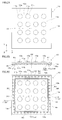
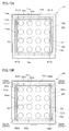
- FIG. 1A and 1B are a plan view and a side cross-sectional view taken along line AA for explaining the laminated lens array unit and the like according to the first embodiment.
- FIG. 2A is a plan view of the first lens array constituting the stacked lens array unit
- FIG. 2B is a side sectional view of the first lens array
- FIG. 2C is a rear view of the first lens array. is there.
- FIG. 3A is a plan view of a second lens array constituting the stacked lens array unit
- FIG. 3B is a side sectional view of the second lens array.
- 4A is a perspective view illustrating a first contact portion of the first lens array
- FIG. 4B is a perspective view illustrating a second contact portion of the second lens array
- 4C illustrates the first contact portion. It is a conceptual diagram explaining the contact state of a 2nd contact part.
- 5A and 5B are a partially enlarged sectional view and a sectional conceptual view for explaining the lens array molding die shown in FIG. 3A and the like. It is a figure explaining the modification of a positioning part or a contact part.
- 7A and 7B are a plan view and a main part enlarged perspective view for explaining a lens array in the multilayer lens array unit of the second embodiment. It is a figure explaining the modification of the lamination type lens array unit of 2nd Embodiment. It is a figure explaining the structure of the lens array in the lamination type lens array unit of 3rd Embodiment.
- FIG. 10A is a back view for explaining the first lens array in the multilayer lens array unit of the fourth embodiment
- the laminated lens array unit 100 of this embodiment is incorporated in an imaging apparatus 1000.
- the illustrated laminated lens array unit 100 is a laminated body in which a plurality (specifically, three) of lens arrays 10, 20, and 30 are stacked, and is used as a compound eye optical system.
- These first, second, and third lens arrays 10, 20, and 30 are square plate-like members extending in parallel to the XY plane, and are stacked in the Z-axis direction perpendicular to the XY plane and joined to each other. ing.
- the imaging apparatus 1000 includes a plurality of detection units (sensor elements) 61 provided corresponding to the individual composite lenses 1a constituting the multilayer lens array unit 100 in addition to the multilayer lens array unit 100 described above. And an image processing unit 65 that performs image processing conforming to a visual field division method or a super-resolution method on an image signal detected by the sensor array 60.
- the laminated lens array unit 100 is bonded to the sensor array 60 and housed in a rectangular frame-like case 50.
- the sensor array 60 may be a plurality of chips arranged, or one chip may be divided into regions.
- the visual field division method refers to a method of obtaining one image by connecting images of different visual fields formed by individual lenses and connecting the images of the respective visual fields by image processing.
- the super-resolution method refers to a method of obtaining one high-resolution image by image processing from images of the same field of view formed by individual lenses.
- the first lens array 10 on the object side is an integrally molded product made of a light-transmitting thermoplastic resin that is an optical material, in other words, an integrated product made of a thermoplastic resin. It has a substantially square outline when viewed from the axis AX direction or the Z-axis direction.
- the first lens array 10 has a plurality of lens elements 10a each of which is an optical element, a support portion 10b that supports the plurality of lens elements 10a from the periphery, and a rectangular frame shape that extends in a strip shape outside the support portion 10b. And an edge portion 10r.
- the plurality of lens elements 10a constituting the first lens array 10 are two-dimensionally arranged on square lattice points (16 ⁇ 4 ⁇ 4 in the illustrated example) arranged in parallel to the XY plane.
- Each lens element 10a has a first optical surface 11a that is convex on the first main surface 10p on the object side, and a second optical surface 11b that is convex on the second main surface 10q on the image side. Both optical surfaces 11a and 11b are aspherical surfaces, for example.
- the support portion 10b is a flat plate-like portion, and includes a plurality of peripheral portions 10c so as to surround each lens element 10a.
- a square frame-shaped edge portion 10r on the periphery or outside in the lateral direction of the support portion 10b is a portion for joining the first lens array 10 to the second lens array 20.
- the intermediate second lens array 20 shown in FIG. 1B is an integrally molded product made of a thermoplastic resin, and has a substantially square outline when viewed from the direction of the central axis AX.
- the second lens array 20 has a plurality of lens elements 20a each of which is an optical element, a support portion 20b that supports the plurality of lens elements 20a from the periphery, and a rectangular frame shape that extends in a strip shape outside the support portion 20b. And an edge portion 20r.
- the plurality of lens elements 20a are two-dimensionally arranged on square lattice points (16 ⁇ 4 ⁇ 4 in the illustrated example) arranged in parallel to the XY plane.
- Each lens element 20a has a first optical surface 21a that is concave on the first main surface 20p on the object side, and a second optical surface 21b that is convex on the second main surface 20q on the image side. Both optical surfaces 21a and 21b are aspherical surfaces, for example.
- the support portion 20b is a flat plate-like portion and includes a plurality of peripheral portions 20c so as to surround each lens element 20a.
- a square frame-shaped edge 20r on the periphery or outside in the lateral direction of the support portion 20b is a portion for joining the second lens array 20 to the first and third lens arrays 10, 30.
- the third lens array 30 on the image side is an integrally molded product made of thermoplastic resin and has a substantially square outline when viewed from the direction of the central axis AX.
- the third lens array 30 has a plurality of lens elements 30a each of which is an optical element, a support portion 30b that supports the plurality of lens elements 30a from the periphery, and a rectangular frame shape that extends in a band shape outside the support portion 30b. And an edge 30r.
- the plurality of lens elements 30a are two-dimensionally arranged on square lattice points (16 ⁇ 4 ⁇ 4 in the illustrated example) arranged in parallel to the XY plane.
- Each lens element 30a has a first optical surface 31a that is concave on the first main surface 30p on the object side, and a second optical surface 31b that is convex on the second main surface 30q on the image side. Both optical surfaces 31a and 31b are aspherical surfaces, for example.
- the support portion 30b is a flat plate-like portion and includes a plurality of peripheral portions 30c so as to surround each lens element 30a.
- a rectangular frame-shaped edge portion 30r at the lateral periphery or outside of the support portion 30b is a portion for joining the third lens array 30 to the second lens array 20.
- the above lens arrays 10, 20, and 30 are positioned with respect to each other with their own structure and weight by sequentially stacking them by machine or manual work. That is, self-alignment is performed. Further, when the lens arrays 10, 20, and 30 are stacked, for example, a photo-curable resin is supplied between the edge portions 10r, 20r, and 30r, and the photo-curing resin is cured and then bonded to each other, thereby being bonded to each other. . By such joining or adhesion, a laminated lens array unit 100 including a large number of synthetic lenses 1a arranged two-dimensionally in a matrix is obtained. The optical axis OA of each synthetic lens 1a is parallel to the entire central axis AX.
- the shape error and the position error cannot be completely eliminated. Therefore, all the positioning regions described later may come into contact with each other by self-alignment. Only the part may abut and the rest may be close, or all may be close. In any case, if the shapes of the lens arrays 10, 20, and 30 are within a certain range of tolerance, for example, the self-alignment causes the first lens array 10 and the second lens array 20 to have tolerances. Can be positioned within.
- a thin light-shielding first aperture plate 41 is disposed between the first lens array 10 and the second lens array 20 so as to be sandwiched and fixed between the pair of support portions 10b and 20b. Although a detailed description is omitted in the first diaphragm plate 41, a large number of openings are formed corresponding to the respective lens elements 10a. Between the 2nd lens array 20 and the 3rd lens array 30, the thin 2nd aperture plate 42 of the light-shielding property pinched
- a thin light-shielding third diaphragm plate 43 fixed to the support portion 30b by bonding or the like is disposed on the image side of the third lens array 30, a thin light-shielding third diaphragm plate 43 fixed to the support portion 30b by bonding or the like is disposed. Although a detailed description is omitted, the third aperture plate 43 has a large number of openings corresponding to the lens elements 30a and the like.
- An incident aperture plate 45 fixed by adhesion to the case 50 or the like is also arranged on the object side of the case 50 that houses the laminated lens array unit 100. Although a detailed description is omitted in the case 50 and the entrance diaphragm plate 45, a large number of openings are formed corresponding to the lens elements 10a and the like.
- FIGS. 2A to 2C are a plan view, a side sectional view, and a back view of the first lens array 10 constituting the laminated lens array unit 100.
- the tapered surface 14a is inclined with respect to the Z axis perpendicular to the main surface, and is in a state of approaching the central axis AX on the front side or the object side.
- the tapered surface 14a is disposed in a rectangle or a square along the edge 10r.
- the taper surface 14a and its periphery constitute an enclosing region SR that encloses the group of lens elements 10a from the outside in a plane parallel to the XY plane.
- this surrounding region SR there are a plurality of linear positioning regions R1 and each linear positioning region R1 functions as a positioning portion.
- the surrounding region SR is a rectangular frame-shaped band, and the linear positioning region R1 is arranged closer to the center in each of the four side portions.
- Each linear positioning region R1 extends elongated along the side portion of the surrounding region SR, and has a length that is, for example, about half or less of the side portion of the surrounding region SR. That is, the four linear positioning regions R1 are distributed and arranged at a plurality of locations so as to surround the support portion 10b or the group of lens elements 10a arranged in a matrix.
- a rectangular frame-shaped flat portion 15 is provided outside the boundary portion 14 at the edge portion 10r of the first lens array 10.
- a flat surface 15 a that is a surface of the flat portion 15 on the second lens array 20 side extends along a plane perpendicular to the central axis AX of the multilayer lens array unit 100.
- 3A and 3B are a plan view and a side sectional view of the second lens array 20.
- the boundary portion 24 on the support portion 20b side of the edge portion 20r extends in a square band shape and has a tapered surface 24a.
- the tapered surface 24a is inclined with respect to the Z axis perpendicular to the main surface, and is in a state of approaching the central axis AX on the front side or the object side.
- the tapered surface 24 a of the second lens array 20 extends substantially in parallel to the tapered surface 14 a of the first lens array 10.
- the tapered surface 24a is disposed in a rectangle or a square along the edge 20r.
- the tapered surface 24a and its periphery constitute an enclosing region SR that encloses the group of lens elements 20a from the outside in a plane parallel to the XY plane.
- a plurality of linear positioning regions R2 exist in the surrounding region SR, and each linear positioning region R2 functions as a positioning portion.
- the surrounding region SR is a rectangular frame-shaped band, and the linear positioning region R2 is disposed closer to the center in each of the four side portions.
- Each linear positioning region R2 is elongated along the side portion of the surrounding region SR, and has a length that is, for example, about half or less of the side portion of the surrounding region SR. That is, the four linear positioning regions R2 are distributed and arranged at a plurality of locations so as to surround the support portion 20b or the group of lens elements 20a arranged in a matrix.
- a square frame-shaped flat portion 25 is provided on the edge 20r of the second lens array 20 outside the boundary portion 24.
- a flat surface 25 a that is a surface of the flat portion 25 on the first lens array 10 side extends along a plane perpendicular to the central axis AX of the multilayer lens array unit 100.
- FIG. 4A is a partially enlarged perspective view for explaining the shape and the like of the linear positioning region R1 of the first lens array 10
- FIG. 4B is a portion for explaining the shape and the like of the linear positioning region R2 of the second lens array 20. It is an expansion perspective view.
- a boundary portion 14 exists as a first contact portion.
- a flat and uniform tapered surface 14a is provided on the surface of the boundary portion 14 as described above.
- a low flange 24b is formed as a second contact portion so as to protrude from the flat tapered surface 24a.
- the surface of the flange portion 24b is a convex surface 24c that approximates a cylindrical surface, and its generatrix L extends along the side portion of the surrounding region SR (see FIG. 2C) in the same manner as the tapered surface 24a.
- FIG. 4C in the state where the first lens array 10 of FIG. 2A and the second lens array 20 of FIG. 3A are overlapped and brought into close contact with each other, the positioning region (first positioning portion) R1 of the first lens array 10 Of the tapered surface 14a of the boundary portion (first contact portion) 14 provided on the side and the flange portion (second contact portion) 24b provided on the positioning region (second positioning portion) R2 side of the second lens array 20
- the convex surface 24c approaches or abuts.
- the tapered surface 14a provided on the boundary portion 14 of the first lens array 10 is on the outside, and the convex surface 24c provided on the flange portion 24b of the second lens array 20 is on the inside.
- the tapered surface 14a of the first lens array 10 is disposed outside the convex surface 24c of the second lens array 20.
- the convex surface 24c is in a line contact state in the vicinity of or in contact with the tapered surface 14a at the position of the generatrix L. After this, when it approaches or contacts in a linear region, including the case where it is close but not completely touched, it is called a line hit state.
- the flat surface 25 a perpendicular to the central axis AX of the flat portion 25 provided in the second lens array 20 faces the flat surface 15 a perpendicular to the central axis AX of the flat portion 15 provided in the first lens array 10. And extended in contact with each other.
- the flat surfaces 15a and 25a of the flat portions 15 and 25 of the first and second lens arrays 10 and 20 are in contact with each other and are disposed opposite to each other, so that the first and second lens arrays 10 and 20 are in the Z-axis direction. Are adjusted, and the inclination with respect to the Z-axis is adjusted.
- both lens arrays 10 and 20 are performed with respect to translation (shift) in the Z-axis direction and rotations ⁇ x and ⁇ y about the XY axis. Further, the tapered surfaces 14a provided in the four linear positioning regions R1 of the first lens array 10 and the convex surfaces 24c provided in the four linear positioning regions R2 of the second lens array 20 are close to each other. Alternatively, by abutting, the lateral displacement between the central axes AX of the first and second lens arrays 10 and 20 is prevented, and the relative rotational posture around the central axis AX is adjusted. That is, the lens arrays 10 and 20 are relatively positioned with respect to the translation (shift) in the XY axis direction and the rotation ⁇ z around the Z axis.
- the flat surfaces 15 a and 25 a of the flat portions 15 and 25 of the first and second lens arrays 10 and 20 are made parallel, and more preferably contacted.
- the tapered surface 14a of the first lens array 10 and the convex surface 24c of the flange portion 24b of the second lens array 20 are brought into contact with or close to each other after being brought into close contact with each other.
- first and second lens arrays 10 and 20 are stacked, first, positioning is performed in advance with respect to rotation around the XY axis (more preferably including translation in the Z-axis direction), Next, positioning is performed with respect to translation in the XY-axis direction and rotation around the Z-axis.
- the flat surfaces 15a and 25a of the flat portions 15 and 25 of both lens arrays 10 and 20 are in close contact in principle, but the tapered surface 14a and the convex surface 24c are disposed in close contact. In some cases, they are arranged close to each other.
- the distance between the tapered surface 14a and the convex surface 24c in the X-axis direction or the Y-axis direction is, for example, 1 ⁇ m or more and 10 ⁇ m or less.
- an accuracy of 10 ⁇ m or less is required for positioning between the lens arrays 10 and 20, and therefore, a taper provided in the positioning region (first positioning portion) R1.
- the set value of the distance between the surface 14a and the convex surface 24c provided in the positioning region (second positioning portion) R2 is also 10 ⁇ m or less.
- the design is ensured by ensuring a set value of 1 ⁇ m or more between the taper surface 14a provided in the linear positioning region R1 and the convex surface 24c provided in the linear positioning region R2 in the X-axis direction or the Y-axis direction. An allowable range such as an error is ensured, and assembly that gives priority to the flat surfaces 15a and 25a of the flat portions 15 and 25 coming into contact with the tapered surface 14a and the convex surface 24c becomes relatively easy.
- the positioning between the first and second lens arrays 10 and 20 has been described above, but the positioning between the second and third lens arrays 20 and 30 is also performed by the same method. That is, although not shown in detail, the second and third lens arrays 20 and 30 are also provided with positioning regions corresponding to the positioning portions, respectively, as shown in FIGS. 4A to 4C.
- the tapered surface (first contact portion) provided in the positioning region of the array 20 and the collar portion (second contact portion) provided in the positioning region of the third lens array 30 are close to or in contact with each other. . In other words, by stacking the second and third lens arrays 20 and 30, positioning can be achieved by their own structure.
- the first lens array 10 is formed by injection molding.
- FIG. 5A is a diagram for explaining a mold for molding the first lens array 10.
- the mold apparatus 70 includes a first mold 71 and a second mold 72.
- the first mold 71 and the second mold 72 are mold-matched at the mold-matching surface PL, and a cavity 70 a is formed between the molds 71 and 72.
- a transfer surface 71c for transferring the shape on the first main surface 10p side of the first lens array 10 is formed on the first mold 71 so as to face the cavity 70a.
- a transfer surface 72c for transferring the shape of the first lens array 10 on the second main surface 10q side is formed.
- the transfer surfaces 71c and 72c have a plurality of optical transfer portions 71g and 72g arranged two-dimensionally at a part thereof in order to transfer the optical surfaces 11a and 11b of the lens element 10a.
- the transfer surfaces 71c and 72c have a transfer portion 72r and the like for transferring the tapered surface 14a and the flat surface 15a of the edge portion 10r.
- the mold part 71i forming the transfer surface 71c is integrally formed
- the mold part 72i forming the transfer surface 72c is formed integrally.
- a gate GA communicating with the cavity 70a is formed.
- the gate GA is disposed not on the center of the transfer surfaces 71c and 72c but on the side, and injection molding is performed by a side gate method.
- FIG. 5B is a cross-sectional view illustrating the entire structure of the mold apparatus 70.
- a runner RA is connected to the cavity 70a of FIG. 5A through a gate GA.
- the runner RA is connected to the sprue SP on the resin supply side.
- the molten resin J from the sprue SP obtained by melting the thermoplastic resin fills the runner RA and fills the cavity 70a through the gate GA.
- a molded product 80 including a portion 83 and a lens array body 84 corresponding to the cavity 70a is formed.
- the gate section 83 is subjected to a gate cut process, and the first lens array 10 is obtained by the lens array body 84 at the tip of the gate section 83.
- the first lens array 10 is formed by integral mold portions 71i and 72i, and has no burr on the first main surface 10p side or the second main surface 10q. That is, it becomes easy to arrange the optical surface 11b of the lens element 10a and the tapered surface 14a and the flat surface 15a of the edge 10r relatively accurately.
- the mold element 72 having the transfer surface for transferring the optical surface 11b of the lens element 10a and the tapered surface 14a of the positioning portion can be simultaneously processed by a processing machine.
- the dimensional accuracy between 10a and positioning region (positioning part) R1 can be improved.
- the second and third lens arrays 20 and 30 are also molded by the same method as that for the first lens array 10. That is, the second and third lens arrays 20 and 30 are also manufactured by injection molding a thermoplastic resin by a side gate method. Similarly to the first lens array 10, the second and third lens arrays 20 and 30 can increase the dimensional accuracy between the lens elements 20a and 30a and the positioning portions (for example, the positioning regions R2,). A multilayer lens array unit 100 can be realized.
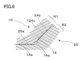
- FIG. 6 is a diagram illustrating a modification of the positioning unit.
- the convex surface 124c of the flange 24b provided in the second lens array 20 is a flat tapered surface.
- the convex surface 124 c of the second lens array 20 comes into contact with the surface when approaching or contacting the tapered surface 14 a of the first lens array 10.
- Part) 24c has a tapered surface that is in contact with or close to the other, so that relative movement in a specific direction is simplified by contact or proximity with the tapered surface such as the tapered surface 14a. Can be regulated.
- the positioning regions (positioning portions) R1 and R2 include a plurality of locations distributed along the edge portion 10r of the first lens array 10 and the edge portion 20r of the second lens array 20.
- the first lens array 10 and the second lens array 20 are moved along the edges of the first lens array 10 and the second lens array 20 by the relative movement restriction using the tapered surface 14a and the convex surface 24c. Space-saving and precise positioning can be achieved with respect to translation and rotation.
- the positioning regions (positioning portions) R1 and R2 between the lens elements 10a. If the positioning regions (positioning portions) R1 and R2 are provided between the lens elements 10a, that is, in the peripheral portions 10c, 20c, and 30c, the positioning convex side becomes thick and the positioning concave side becomes thin. For this reason, when molding by injection molding, the resin is less likely to flow through the thin-walled portion, the molding resin pressure is less likely to be applied to the lens element 10a, resulting in transfer failure, and the flow of the resin is disturbed, resulting in welds. To do. On the other hand, when the positioning portion is provided outside the lens element 10a, that is, at the edge portions 10r, 20r, and 30r, only the outer portion is thinned, so that transfer defects and weld problems are less likely to occur.
- the first lens array 10 is placed on the second lens array 20 with rough alignment.
- the smooth combination and precise positioning of the first lens array 10 and the second lens array 20 are possible.
- the positioning portion including the tapered surface 14a, the convex surface 24c, and the like is disposed on the edge side or the outer peripheral side of the first and second lens arrays 10, 20, the function of the optical surface of the lens elements 10a, 20a, 30a. Can be prevented, and a design in which substantially the entire surface of the sensor array 60 of the image pickup apparatus 1000 is used as an image plane is also possible, which makes it easy to achieve high image quality.
- the diaphragm plates 41 to 43 are provided at positions between the lens elements 10a as a countermeasure against crosstalk.
- the positioning regions (positioning portions) R1 and R2 are arranged outside the lens element 10a or the support portion 10b. Since they are provided, it is easy to avoid interference between them. That is, if the positioning regions (positioning portions) R1 and R2 are provided between the lens elements 10a, they are likely to interfere with the diaphragm plates 41 to 43 and the like, and it becomes difficult to dispose the diaphragm plates 41 to 43, thereby increasing crosstalk. there is a possibility.
- the positioning structure between the first and second lens arrays 10 and 20 can be switched up and down. That is, the tapered surface 14a of the boundary portion (first contact portion) 14 provided on the positioning region (first positioning portion) R1 side of the first lens array 10 is similar to the convex surface 24c of the flange portion 24b shown in FIG. 4B. Can be aligned or positioned by bringing the convex surface on the first lens array 10 side and the tapered surface 24a of the second lens array 20 close to or in contact with each other.
- the flat surface 15 a provided on the flat portion 15 of the first lens array 10 and the flat surface 25 a provided on the flat portion 25 of the second lens array 20 do not necessarily need to extend over the entire flat portions 15 and 25. However, it is only necessary to extend so as to be able to contact each other only at a plurality of positions that enable positioning during stacking.
- the laminated lens array unit and the like according to the second embodiment will be described.
- the laminated lens array unit of the second embodiment is a modification of the laminated lens array unit of the first embodiment, and items that are not particularly described are the same as those of the first embodiment.
- a plurality of point-like positioning regions R22 exist in the surrounding region SR of the second lens array 20, and each point-like positioning region R22 functions as a positioning unit.
- the dot positioning regions R22 are arranged at two locations in each of the four side portions constituting the surrounding region SR. That is, eight point-like positioning regions R22 are arranged in a separated state so as to be distributed along the surrounding region SR.
- a low and short protrusion 124b is formed in the point-like positioning region R22 so as to protrude from the flat tapered surface 24a as the second contact portion.
- the protrusion 124b has a dome-like outer shape close to a cylinder like a halves or rugby balls, and the surface of the protrusion 124b is a convex surface 124c close to a hemisphere or a cylinder. Strictly speaking, when the convex surface 124c approaches or comes into contact with the tapered surface 14a of the first lens array 10, the convex surface 124c is in a point hit state from the standpoint of effectiveness in positioning. In addition, after this, when it approaches or contacts in a dotted line-like or short linear area including the case where it is close but not completely touched, it will be referred to as a spotted state.
- both the lens arrays 10 and 20 are formed by the tapered surface 14a of the boundary portion (first contact portion) 14 and the convex surface (second contact portion) 124c of the projection portion (second contact portion) 124b. It is possible to precisely position in a space-saving manner with respect to translation and rotation in the XY plane along these edges.
- the dot positioning region R22 can be thinned out to the minimum necessary. Specifically, as shown in FIG. 8, in one side portion SR1, among the four side portions constituting the surrounding region SR extending along the boundary portion 24 of the second lens array 20, dots are formed in two places. The positioning region R22 is arranged, and in the remaining three side portions SR2, the dot-like positioning region R22 is arranged at one place. In this case, translation in the XY plane is restricted by all side portions SR1 and SR2, and rotation in the XY plane is restricted by the side portion SR1 alone.
- the laminated lens array unit according to the third embodiment will be described below.
- the laminated lens array unit of the third embodiment is a modified example of the laminated lens array unit of the first and second embodiments, and items not specifically described are the same as those of the first embodiment. .
- the linear positioning region R2 is arranged at one location, and in the remaining three side portions SR2, one location is provided.
- a point-shaped positioning region R22 is arranged in the area. In this case, translation in the XY plane is restricted by all side portions SR1 and SR2, and rotation in the XY plane is restricted by the side portion SR1 alone.
- the laminated lens array unit of the fourth embodiment is a modification of the laminated lens array unit of the first embodiment, and items that are not particularly described are the same as those of the first embodiment.
- each linear positioning region R13 functions as a positioning unit. Specifically, the linear positioning region R13 is disposed in each of the four corner portions constituting the surrounding region SR. In each linear positioning region R13, a boundary portion 14 is formed as a first contact portion, and a tapered surface 14a is formed as a flat surface.
- a plurality of linear positioning regions R23 exist in the surrounding region SR of the second lens array 20, and each linear positioning region R23 functions as a positioning unit. Specifically, the linear positioning region R23 is arranged in each of the four corner portions constituting the surrounding region SR. Each linear positioning region R23 is formed with a low and long protruding portion 224b as a second contact portion so as to protrude from the flat tapered surface 24a.
- the tapered surface 14a of the boundary portion (first contact portion) 14 on the first lens array 10 side and the protrusion on the second lens array 20 side when the first and second lens arrays 10 and 20 are stacked, the tapered surface 14a of the boundary portion (first contact portion) 14 on the first lens array 10 side and the protrusion on the second lens array 20 side.
- the convex surface 224c of the portion (second contact portion) 224b approaches or comes into contact, automatic positioning by line hit is performed. That is, the tapered surface (first contact portion) 14a and the convex surface (second contact portion) 224c save both the lens arrays 10 and 20 with respect to translation and rotation in the XY plane along their edges. Can be positioned precisely.
- the laminated lens array unit according to the fifth embodiment will be described below.
- the laminated lens array unit of the fifth embodiment is a modification of the laminated lens array unit of the first embodiment, and items not specifically described are the same as those of the first embodiment.
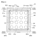
- linear positioning regions R23 at one location and dotted positioning regions R24 at multiple locations, each functioning as a positioning unit.
- the linear positioning region R23 is disposed in one corner portion SR3 among the four corner portions constituting the surrounding region SR, and the dotted positioning region R24 is disposed in the remaining three corner portions SR4.
- a low and long protruding portion 224b is formed as a second contact portion so as to protrude from the flat tapered surface 24a.
- a low and short protrusion 124b is formed as a second contact portion so as to protrude from the flat tapered surface 24a.
- the taper surface (first abutting portion) 14a and the convex surface (second abutting portion) 224c are automatically positioned by line contact, and the tapered surface (first abutting portion) 14a and the convex surface (convex surface) are convex. Automatic positioning by point hitting is performed by the surface (second contact portion) 124c.
- the long protrusion 224b is provided at one of the four corners constituting the surrounding region SR.
- the long protrusion 224b can be provided at two or three of the four corners. .
- FIG. 12 shows an example in which a part of the first lens array 10 shown in FIG. 11 is changed.
- a set of two point positioning regions R25 is arranged in place of one linear positioning region R23 at or near one corner portion SR3. With these two point-like positioning regions R25, both lens arrays 10 and 20 can be positioned with respect to rotation in the XY plane along their edges.
- FIG. 13 shows another example in which a part of the first lens array 10 shown in FIG. 11 is changed.
- only two adjacent corner portions SR4 are utilized, and one side portion SR1 (fourth) different from the three side portions SR1 (first to third side portions) constituting the two corner portions SR4.
- one linear positioning region R2 is arranged in the side portion SR1r.
- the two lens arrays 10 and 20 can be positioned with respect to translation and rotation in the XY plane along these edges by the two point-like positioning regions R24 and the one linear positioning region R2.
- Two adjacent corner portions SR4 may be per line or per plurality of points, and one side portion SR1 (fourth side portion SR1r) may be per point.
- FIG. 14 is another example in which a part of the first lens array 10 shown in FIG. 11 is changed.
- two point-like positioning regions R24 are arranged in the two corner portions SR4, and a positioning portion composed of a pair of point-like positioning regions R25 is arranged in the two corner portions SR3 or in the vicinity thereof.
- Positioning relating to rotation in the XY plane is mainly achieved by the pair of point-like positioning regions R25.
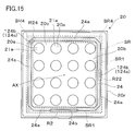
- FIG. 15 shows another example in which a part of the first lens array 10 shown in FIG. 11 is changed.
- one point-like positioning region R24 is arranged in one corner portion SR4, and two side portions SR1 (first and second side portions) different from the two side portions SR1 (first and second side portions) adjacent to the corner portion SR4 ( Among the third and fourth side portions), one linear positioning region R2 is disposed on one side, and one point positioning region R22 is disposed on the other side.
- both the lens arrays 10 and 20 can be positioned with respect to translation and rotation in the XY plane along these edges by one linear positioning region R2 and one point positioning region R24.
- a point-like positioning region R22 may be provided in each of the third and fourth side portions.
- the laminated lens array unit of the sixth embodiment is a modification of the laminated lens array unit of the first embodiment, and items that are not particularly described are the same as those of the first embodiment.
- a linear positioning region R26 exists over the entire circumference corresponding to the boundary portion 24 in the rectangular surrounding region SR of the second lens array 20, and this functions as a positioning portion. . That is, the tapered surface 24a of the boundary portion 24 functions as the second contact portion as it is.
- Automatic positioning is performed by the proximity or contact of the tapered surface 24a of the boundary portion (second contact portion) 24 on the second lens array 20 side as shown in FIG. 16A or the like. That is, both the lens arrays 10 and 20 can be accurately positioned in a space-saving manner with respect to translation and rotation in the XY plane along these edges by the both tapered surfaces 14a and 24a.
- the tapered surfaces 14a and 24a do not need to extend continuously, and the tapered surfaces 14a and 24a are intermittently in contact with each other by providing shallow depressions or the like at appropriate positions of the tapered surfaces 14a and 24a. Or it can be close.
- the laminated lens array unit according to the seventh embodiment will be described below.
- the laminated lens array unit of the seventh embodiment is a modification of the laminated lens array unit of the second embodiment, and items not specifically described are the same as those of the second embodiment.
- the edge portion 20r is provided with a tapered portion 20t having a slightly tapered surface so as to become narrower toward the main surface on the image side.
- a protrusion 26 having a semicircular vertical reference surface 26a with the image side parallel to the central axis AX as a bottom is provided on a part of the tapered portion 20t.
- the vertical reference surface 26a is formed simultaneously with the molding of the lens array 20 by a molding surface accurately formed on the mold so as to be parallel to the central axis AX.
- the vertical reference surface 26a for example, when the optical performance of the lens array 20 is measured by an inspection machine, the vertical reference surface 26a is brought into contact with a jig or the like of the inspection machine to The reference surface 26a can be used for positioning the lens array 20 with respect to the inspection machine, and measurement can be performed smoothly.
- a plurality of vertical reference surfaces 26a are provided on each side of the edge 20r.
- the lens array 10 can also be provided with a similar reference surface at the edge 10r.
- the shape of the vertical reference planes provided at the edges 10r and 20r is not limited to a semicircular shape, and may be an elliptical shape or a polygonal shape such as a trapezoidal shape or a triangular shape.
- the diameter be reduced in accordance with the taper or inclination of the taper as in the present embodiment.
- the inclination of the tapered portion 20t is not limited to be narrow on the image side, but can be narrow on the object side.
- a taper may be provided at the edge and a vertical reference plane may be provided.
- the laminated lens array unit and the like according to the embodiment have been described above, but the laminated lens array unit and the like according to the present invention are not limited to the above examples.
- the arrangement of the lens elements 10a, 20a, 30a constituting the lens arrays 10, 20, 30 and the shape of the optical surfaces 11a, 11b,... are used or the specifications of the stacked lens array unit 100 or the imaging device 1000. It can be changed as appropriate according to the situation.
- the lens elements 10a, 20a, and 30a are not limited to being arranged at 4 ⁇ 4 lattice points, but can be arranged at lattice points of 3 ⁇ 3, 5 ⁇ 5, and the like.
- the lens array constituting the laminated lens array unit 100 is not limited to the above-described three layers (lens arrays 10, 20, 30), but may be two layers (only the lens arrays 10, 20) or four layers or more. Can do.
- the tapered surfaces 14a and 24a do not have to be completely flat, and can be tapered surfaces having a slight concave or convex curvature.
- the outline shape of the laminated lens array unit 100 or the lens arrays 10, 20, and 30 and the shape of the surrounding region are generally rectangular or square, that is, a quadrangle, but can be slightly modified.
- a lens array having an outline of an octagon or the like close to a quadrangle with a corner dropped (which is also included in a substantially quadrangular outline) is also an element constituting the multilayer lens array unit according to the present invention. it can.
- the number of the flanges 24b and the protrusions 124b and 224b described above can be added in the surplus space, but the processing accuracy is required to reduce the number of the flanges 24b and the protrusions 124b and 224b. This is advantageous from the viewpoint of reducing component costs.
Landscapes
- Physics & Mathematics (AREA)
- General Physics & Mathematics (AREA)
- Optics & Photonics (AREA)
- Lens Barrels (AREA)
- Transforming Light Signals Into Electric Signals (AREA)
- Studio Devices (AREA)
Abstract
La présente invention porte sur une unité de réseaux de lentilles empilés qui permet d'obtenir une précision d'assemblage élevée et qui peut être moulée avec une grande précision, et sur un dispositif de capture d'image dans lequel l'unité de réseaux de lentilles empilés est incorporée. Une surface effilée (une première partie de contact) (14a) sur le côté du premier réseau de lentilles (10) et/ou une surface convexe (une seconde partie de contact) (24c) sur le côté du second réseau de lentilles (20) présente une surface effilée qui est en contact avec l'autre ou proche de cette dernière, ce qui permet de restreindre facilement le déplacement relatif dans une direction spécifiée. En outre, dans l'unité de réseaux de lentilles empilés susmentionnée (100), des régions de positionnement (parties de positionnement) (R1, R2) sont situées dans une région alentour (SR) comprenant une pluralité de places réparties le long du bord (10r) du premier réseau de lentilles (10) et du bord (20r) du second réseau de lentilles (20), permettant ainsi de positionner le premier réseau de lentilles (10) et le second réseau de lentilles (20) avec précision et d'une manière compacte par rapport à une translation et à une rotation dans le plan X-Y le long des bords.
Priority Applications (1)
| Application Number | Priority Date | Filing Date | Title |
|---|---|---|---|
| JP2015519970A JP6380391B2 (ja) | 2013-05-31 | 2014-05-30 | 積層型レンズアレイユニット及び撮像装置 |
Applications Claiming Priority (2)
| Application Number | Priority Date | Filing Date | Title |
|---|---|---|---|
| JP2013-116515 | 2013-05-31 | ||
| JP2013116515 | 2013-05-31 |
Publications (1)
| Publication Number | Publication Date |
|---|---|
| WO2014192933A1 true WO2014192933A1 (fr) | 2014-12-04 |
Family
ID=51988951
Family Applications (1)
| Application Number | Title | Priority Date | Filing Date |
|---|---|---|---|
| PCT/JP2014/064487 Ceased WO2014192933A1 (fr) | 2013-05-31 | 2014-05-30 | Unité de réseaux de lentilles empilés et dispositif de capture d'image |
Country Status (2)
| Country | Link |
|---|---|
| JP (1) | JP6380391B2 (fr) |
| WO (1) | WO2014192933A1 (fr) |
Cited By (3)
| Publication number | Priority date | Publication date | Assignee | Title |
|---|---|---|---|---|
| JP2018010270A (ja) * | 2016-07-15 | 2018-01-18 | エーエーシー テクノロジーズ ピーティーイー リミテッドAac Technologies Pte.Ltd. | レンズモジュール |
| US20190259741A1 (en) * | 2015-04-20 | 2019-08-22 | Advanced Semiconductor Engineering, Inc. | Optical sensor module and method for manufacturing the same |
| KR20250073491A (ko) | 2022-10-31 | 2025-05-27 | 니혼 이타가라스 가부시키가이샤 | 렌즈 어레이 |
Families Citing this family (1)
| Publication number | Priority date | Publication date | Assignee | Title |
|---|---|---|---|---|
| KR102742270B1 (ko) * | 2019-11-11 | 2024-12-13 | 에스케이하이닉스 주식회사 | 이미지 센서 |
Citations (7)
| Publication number | Priority date | Publication date | Assignee | Title |
|---|---|---|---|---|
| JP2003329808A (ja) * | 2002-05-16 | 2003-11-19 | Olympus Optical Co Ltd | 接合レンズアレイ |
| JP2007329714A (ja) * | 2006-06-08 | 2007-12-20 | Funai Electric Co Ltd | 複眼撮像装置 |
| WO2009119192A1 (fr) * | 2008-03-26 | 2009-10-01 | コニカミノルタオプト株式会社 | Réseau de lentilles cimentées, lentille cimentée et procédé de production d'un réseau de lentilles cimentées |
| JP3160406U (ja) * | 2009-04-15 | 2010-06-24 | 一品光学工業股▲ふん▼有限公司 | 方形積層ガラスレンズモジュール(Rectangularstackedglasslensmodule) |
| JP2011013577A (ja) * | 2009-07-03 | 2011-01-20 | Sharp Corp | 多層レンズ、積層型ウェハレンズおよびその製造方法 |
| WO2012165281A1 (fr) * | 2011-06-01 | 2012-12-06 | コニカミノルタアドバンストレイヤー株式会社 | Unité d'œil composé |
| WO2013065455A1 (fr) * | 2011-10-31 | 2013-05-10 | コニカミノルタ株式会社 | Procédé de fabrication d'un bloc de lentilles, matrice de lentilles et bloc de lentilles |
Family Cites Families (4)
| Publication number | Priority date | Publication date | Assignee | Title |
|---|---|---|---|---|
| JPH10170703A (ja) * | 1996-12-12 | 1998-06-26 | Ricoh Co Ltd | アレイ状レンズ及びその製造方法 |
| JP2000352606A (ja) * | 1999-06-11 | 2000-12-19 | Rohm Co Ltd | レンズアレイアッセンブリおよびこれを用いた画像表示装置 |
| JP2003095708A (ja) * | 2001-09-25 | 2003-04-03 | Olympus Optical Co Ltd | 接合レンズアレイの製造方法及び接合レンズの製造方法並びにレンズアレイ |
| DE102009055083B4 (de) * | 2009-12-21 | 2013-12-05 | Fraunhofer-Gesellschaft zur Förderung der angewandten Forschung e.V. | Optischer Schichtstapel und Verfahren zu dessen Herstellung |
-
2014
- 2014-05-30 WO PCT/JP2014/064487 patent/WO2014192933A1/fr not_active Ceased
- 2014-05-30 JP JP2015519970A patent/JP6380391B2/ja not_active Expired - Fee Related
Patent Citations (7)
| Publication number | Priority date | Publication date | Assignee | Title |
|---|---|---|---|---|
| JP2003329808A (ja) * | 2002-05-16 | 2003-11-19 | Olympus Optical Co Ltd | 接合レンズアレイ |
| JP2007329714A (ja) * | 2006-06-08 | 2007-12-20 | Funai Electric Co Ltd | 複眼撮像装置 |
| WO2009119192A1 (fr) * | 2008-03-26 | 2009-10-01 | コニカミノルタオプト株式会社 | Réseau de lentilles cimentées, lentille cimentée et procédé de production d'un réseau de lentilles cimentées |
| JP3160406U (ja) * | 2009-04-15 | 2010-06-24 | 一品光学工業股▲ふん▼有限公司 | 方形積層ガラスレンズモジュール(Rectangularstackedglasslensmodule) |
| JP2011013577A (ja) * | 2009-07-03 | 2011-01-20 | Sharp Corp | 多層レンズ、積層型ウェハレンズおよびその製造方法 |
| WO2012165281A1 (fr) * | 2011-06-01 | 2012-12-06 | コニカミノルタアドバンストレイヤー株式会社 | Unité d'œil composé |
| WO2013065455A1 (fr) * | 2011-10-31 | 2013-05-10 | コニカミノルタ株式会社 | Procédé de fabrication d'un bloc de lentilles, matrice de lentilles et bloc de lentilles |
Cited By (4)
| Publication number | Priority date | Publication date | Assignee | Title |
|---|---|---|---|---|
| US20190259741A1 (en) * | 2015-04-20 | 2019-08-22 | Advanced Semiconductor Engineering, Inc. | Optical sensor module and method for manufacturing the same |
| US11257799B2 (en) * | 2015-04-20 | 2022-02-22 | Advanced Semiconductor Engineering, Inc. | Optical sensor module and method for manufacturing the same |
| JP2018010270A (ja) * | 2016-07-15 | 2018-01-18 | エーエーシー テクノロジーズ ピーティーイー リミテッドAac Technologies Pte.Ltd. | レンズモジュール |
| KR20250073491A (ko) | 2022-10-31 | 2025-05-27 | 니혼 이타가라스 가부시키가이샤 | 렌즈 어레이 |
Also Published As
| Publication number | Publication date |
|---|---|
| JP6380391B2 (ja) | 2018-08-29 |
| JPWO2014192933A1 (ja) | 2017-02-23 |
Similar Documents
| Publication | Publication Date | Title |
|---|---|---|
| JP6380391B2 (ja) | 積層型レンズアレイユニット及び撮像装置 | |
| JP5812521B2 (ja) | 複眼ユニット | |
| TWI544248B (zh) | 攝像透鏡單元之製造方法、以及攝像透鏡單元 | |
| WO2018023887A1 (fr) | Module de photographie, ensemble de carte de circuit imprimé moulé, ensemble photosensible moulé correspondant et procédés de fabrication | |
| TW201806087A (zh) | 攝像模組及其模塑電路板元件與製造方法 | |
| CN107077062A (zh) | 表皮用支承框及制造方法 | |
| WO2012043191A1 (fr) | Lentille en verre | |
| TWM557833U (zh) | 攝像模組、模塑感光元件、成型模具及其電子設備 | |
| WO2009119192A1 (fr) | Réseau de lentilles cimentées, lentille cimentée et procédé de production d'un réseau de lentilles cimentées | |
| WO2011093502A1 (fr) | Procédé de fabrication d'un objectif, dispositif d'imagerie, procédé de fabrication d'une filière, filière de moulage, et procédé de formation d'une matrice de lentilles en verre | |
| JP2013174784A (ja) | カメラモジュール、カメラモジュールの組み付け方法、レンズアレイの製造方法及び金型 | |
| TWI432815B (zh) | 鏡頭模組 | |
| JP2012154825A (ja) | 撮像モジュール | |
| JP6536955B2 (ja) | レンズアレイ、レンズアレイ積層体、及び、これらの製造方法 | |
| JP5345455B2 (ja) | 多層レンズ、積層型ウェハレンズおよびその製造方法 | |
| WO2014119751A1 (fr) | Réseau de lentilles, système optique oculaire composite et procédé de production de l'ensemble de lentilles | |
| JP2010147917A (ja) | 撮像素子ユニット及び撮像装置 | |
| JP2014235307A (ja) | レンズアレイユニット及び撮像装置 | |
| JP6439604B2 (ja) | 光学素子及び光学素子の製造方法 | |
| WO2014119737A1 (fr) | Système optique d'œil composé, dispositif de capture d'images et procédé de production d'un système optique d'œil composé | |
| JP2006235262A (ja) | 光コリメータアレイ | |
| JP7665414B2 (ja) | プラスチックレンズおよび機器 | |
| JP5254139B2 (ja) | 多層レンズ、積層型ウェハレンズおよびその製造方法 | |
| JPWO2014119738A1 (ja) | 複眼光学系、撮像装置、及び複眼光学系の製造方法 | |
| JP2006100312A (ja) | 光半導体装置および測距モジュール |
Legal Events
| Date | Code | Title | Description |
|---|---|---|---|
| 121 | Ep: the epo has been informed by wipo that ep was designated in this application |
Ref document number: 14803453 Country of ref document: EP Kind code of ref document: A1 |
|
| ENP | Entry into the national phase |
Ref document number: 2015519970 Country of ref document: JP Kind code of ref document: A |
|
| NENP | Non-entry into the national phase |
Ref country code: DE |
|
| 122 | Ep: pct application non-entry in european phase |
Ref document number: 14803453 Country of ref document: EP Kind code of ref document: A1 |