WO2014192984A2 - Procédé de fabrication d'un corps emballé d'articles pour l'hygiène, et dispositif de fabrication - Google Patents
Procédé de fabrication d'un corps emballé d'articles pour l'hygiène, et dispositif de fabrication Download PDFInfo
- Publication number
- WO2014192984A2 WO2014192984A2 PCT/JP2014/073689 JP2014073689W WO2014192984A2 WO 2014192984 A2 WO2014192984 A2 WO 2014192984A2 JP 2014073689 W JP2014073689 W JP 2014073689W WO 2014192984 A2 WO2014192984 A2 WO 2014192984A2
- Authority
- WO
- WIPO (PCT)
- Prior art keywords
- packaging sheet
- label
- package
- continuous body
- line
- Prior art date
- Legal status (The legal status is an assumption and is not a legal conclusion. Google has not performed a legal analysis and makes no representation as to the accuracy of the status listed.)
- Ceased
Links
Images






Classifications
-
- B—PERFORMING OPERATIONS; TRANSPORTING
- B65—CONVEYING; PACKING; STORING; HANDLING THIN OR FILAMENTARY MATERIAL
- B65B—MACHINES, APPARATUS OR DEVICES FOR, OR METHODS OF, PACKAGING ARTICLES OR MATERIALS; UNPACKING
- B65B9/00—Enclosing successive articles, or quantities of material, e.g. liquids or semiliquids, in flat, folded, or tubular webs of flexible sheet material; Subdividing filled flexible tubes to form packages
- B65B9/06—Enclosing successive articles, or quantities of material, in a longitudinally-folded web, or in a web folded into a tube about the articles or quantities of material placed upon it
- B65B9/067—Enclosing successive articles, or quantities of material, in a longitudinally-folded web, or in a web folded into a tube about the articles or quantities of material placed upon it the web advancing continuously
-
- B—PERFORMING OPERATIONS; TRANSPORTING
- B65—CONVEYING; PACKING; STORING; HANDLING THIN OR FILAMENTARY MATERIAL
- B65B—MACHINES, APPARATUS OR DEVICES FOR, OR METHODS OF, PACKAGING ARTICLES OR MATERIALS; UNPACKING
- B65B57/00—Automatic control, checking, warning, or safety devices
- B65B57/02—Automatic control, checking, warning, or safety devices responsive to absence, presence, abnormal feed, or misplacement of binding or wrapping material, containers, or packages
-
- B—PERFORMING OPERATIONS; TRANSPORTING
- B65—CONVEYING; PACKING; STORING; HANDLING THIN OR FILAMENTARY MATERIAL
- B65B—MACHINES, APPARATUS OR DEVICES FOR, OR METHODS OF, PACKAGING ARTICLES OR MATERIALS; UNPACKING
- B65B61/00—Auxiliary devices, not otherwise provided for, for operating on sheets, blanks, webs, binding material, containers or packages
- B65B61/02—Auxiliary devices, not otherwise provided for, for operating on sheets, blanks, webs, binding material, containers or packages for perforating, scoring, slitting, or applying code or date marks on material prior to packaging
-
- B—PERFORMING OPERATIONS; TRANSPORTING
- B65—CONVEYING; PACKING; STORING; HANDLING THIN OR FILAMENTARY MATERIAL
- B65B—MACHINES, APPARATUS OR DEVICES FOR, OR METHODS OF, PACKAGING ARTICLES OR MATERIALS; UNPACKING
- B65B61/00—Auxiliary devices, not otherwise provided for, for operating on sheets, blanks, webs, binding material, containers or packages
- B65B61/18—Auxiliary devices, not otherwise provided for, for operating on sheets, blanks, webs, binding material, containers or packages for making package-opening or unpacking elements
- B65B61/184—Auxiliary devices, not otherwise provided for, for operating on sheets, blanks, webs, binding material, containers or packages for making package-opening or unpacking elements by applying tabs over discharge openings, e.g. over discharge openings defined by tear or score lines
-
- B—PERFORMING OPERATIONS; TRANSPORTING
- B65—CONVEYING; PACKING; STORING; HANDLING THIN OR FILAMENTARY MATERIAL
- B65D—CONTAINERS FOR STORAGE OR TRANSPORT OF ARTICLES OR MATERIALS, e.g. BAGS, BARRELS, BOTTLES, BOXES, CANS, CARTONS, CRATES, DRUMS, JARS, TANKS, HOPPERS, FORWARDING CONTAINERS; ACCESSORIES, CLOSURES, OR FITTINGS THEREFOR; PACKAGING ELEMENTS; PACKAGES
- B65D75/00—Packages comprising articles or materials partially or wholly enclosed in strips, sheets, blanks, tubes or webs of flexible sheet material, e.g. in folded wrappers
- B65D75/52—Details
- B65D75/58—Opening or contents-removing devices added or incorporated during package manufacture
- B65D75/5827—Tear-lines provided in a wall portion
- B65D75/5833—Tear-lines provided in a wall portion for tearing out a portion of the wall
- B65D75/5838—Tear-lines provided in a wall portion for tearing out a portion of the wall combined with separate fixed tearing means, e.g. tabs
Definitions
- the present invention relates to a method and apparatus for manufacturing a package of sanitary articles such as pocket-type wet tissue.
- sanitary articles such as pocket-type wet tissues and panty liners are provided to the market in the form of a package packaged in a single packaging sheet. And this hygiene article is taken out from a packaging sheet, for example one by one, and used.
- Patent Document 1 discloses a technique in which an openable / closable lid is formed after opening a packaging sheet as an example of such a package.
- packaging sheet 27 disclosed in Patent Document 1 will be schematically described with reference to FIGS. 2A, 2B, and 4 described later.
- the packaging sheet 27 is first formed with perforations 27M so as to substantially surround the predetermined portion 27cap, and a label 28 is joined to the portion corresponding to the perforations 27M.
- the packaging sheet 27 is opened by cutting the perforation 27M by picking up the label 28 and pulling it up. That is, as shown in FIG. 4, the predetermined portion 27cap is generally separated from the packaging sheet 27, and the packaging sheet 27 is formed with an outlet 27h having a shape corresponding to the predetermined portion 27cap.
- the predetermined portion 27cap is not completely separated from the packaging sheet 27, that is, is connected to the packaging sheet 27 via the unformed portion 27Mb of the perforation 27M. Therefore, the predetermined portion 27cap is an open / close lid 27cap that can be opened and closed with the unformed portion 27Mb as a hinge. Further, the label 28 is bonded to the predetermined portion 27cap, which mainly becomes the opening / closing lid 27cap, of the packaging sheet 27 with an adhesive, whereby the opened label 28 is opened / closed integrally with the opening / closing lid 27cap.
- the label 28 protrudes from the tip portion 27Mt of the opening / closing lid 27cap, and can be rejoined to the portion 27ha around the take-out port 27h of the packaging sheet 27 by the adhesive of the protruding portion 28p. It has become.
- the user of the package 21 takes out a hygienic article such as wet tissue from the take-out port 27h of the package sheet 27, the user can fix the take-out port 27h in the closed state with the open / close lid 27cap. .
- the sanitary article can be put into a bag while being kept clean.
- the sanitary article G11 is transported at a predetermined transport pitch PG11 along the transport direction (MD direction) by the transport device 32 such as a conveyor. Note that a space is provided between the sanitary articles G11 and G11 adjacent in the transport direction based on the predetermined pitch PG11.
- another transporting device 34 transports the continuous body 27a of the packaging sheet 27 continuous in the transporting direction, and the perforation forming device 40 and the labeler device 50 are located at predetermined positions in the transporting direction. Arranged in order. Therefore, when passing through the perforation forming device 40, the perforation 27M is formed in the portion corresponding to the sanitary article G11 in the continuous body 27a, and when passing through the labeler device 50, the continuous A label 28 is bonded to the body 27a for each perforation 27M.
- the continuous body 27a of the packaging sheet 27 is joined to the transport device 32 that transports the sanitary article G11.
- the continuous body 27a passes through the bending guide member 70.
- the end portions 27aew and 27aew in the width direction (CD direction) intersecting the transport direction in the continuous body 27a of the packaging sheet 27 are bent, respectively, so that the continuous body 27a is formed into a cylindrical shape.
- the continuum 27a is encased in the sanitary article G11.
- the sealing device 80 seals the continuum 27a of the packaging sheet 27 in a state of wrapping the sanitary article G11. 27s of sealing parts are formed in the part between hygiene articles G11 and G11 among 27a.
- the said cutter apparatus 90 cut disconnects the continuous body 27a of the packaging sheet 27 by making the position contained in the sealing part 27s into the cutting position Pc, and has the above.
- a package 21 formed by packaging the article G11 is generated.
- the formation position in the transport direction of the portion 27Mt of the perforation 27M that becomes the tip of the opening / closing lid 27cap is, for example, 30 mm ⁇ 10 mm from the cutting position Pc.
- the joining position of the downstream end portion 28ed in the conveyance direction of the label 28 is managed so as to fall within a range of, for example, 23 mm ⁇ 5 mm from the cutting position Pc. That is, both positions are managed based on the cutting position Pc. Along with this, those out of these ranges are rejected, that is, rejected and discarded.
- the function of the label 28 is that the perforation 27M is surely cut and opened by pinching and lifting at the time of opening, and the opening / closing lid 27cap is closed by the adhesive of the label 28 after opening.
- it is determined that the one that performs the function of the label 28 as described above is acceptable when the determination is made based on the formation position of the perforation 27M for the determination of pass / fail of the bonding position of the label 28. In other words, it is considered that it is possible to appropriately determine whether or not the joining position of the label 28 is acceptable.
- the present invention has been made in view of the above-described conventional problems, and its purpose is to provide a hygienic package sheet in which an opening / closing lid is formed after opening by being cut along a weak line such as a perforation.
- a weak line such as a perforation.
- the main invention for achieving the above object is: A method for producing a package in which at least one sanitary article is packaged by a packaging sheet,
- the packaging sheet that packages the sanitary article has a portion that becomes an opening / closing lid after opening by being cut along the line of weakness when opened, and a portion corresponding to the line of weakness in the packaging sheet is opened
- a label that sometimes becomes a knob is joined so that it can be fixed with the opening and closing lid closed after opening
- the manufacturing method includes: Transporting a plurality of the sanitary articles along a transport direction, transporting the sanitary articles adjacent to each other in the transport direction with a gap therebetween; Forming the line of weakness in a portion corresponding to the sanitary article in a continuous body of the packaging sheet continuous in the transport direction; Bonding the label for each line of weakness to the continuum of the packaging sheet; Determining pass / fail of the bonding position of the label in the packaging sheet based on the relative positional relationship between the weak line and the label in the continuum of the packaging sheet; Wrapping
- An apparatus for manufacturing a package in which at least one sanitary article is packaged by a packaging sheet The packaging sheet that packages the sanitary article has a portion that becomes an opening / closing lid after opening by being cut along the line of weakness when opened, and a portion corresponding to the line of weakness in the packaging sheet is opened A label that sometimes becomes a knob is joined so that it can be fixed with the opening and closing lid closed after opening,
- the manufacturing apparatus includes: An apparatus for conveying a plurality of the hygiene articles along a conveying direction, wherein the apparatus conveys the sanitary articles adjacent to each other in the conveying direction with a gap therebetween; An apparatus for forming the line of weakness in a portion corresponding to the sanitary article in the continuous body of the packaging sheet that is continuous in the transport direction; An apparatus for joining the label for each line of weakness with respect to the continuous body of the packaging sheet; An apparatus for determining pass / fail of the bonding position of the label in the packaging sheet, based on the relative positional relationship between the weak line and the label in the continuum of the packaging
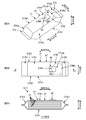
- FIG. 1A is a schematic plan view of the panty liner 1
- FIG. 1B is a cross-sectional view taken along the line BB in FIG. 1A
- FIG. 1C is a schematic plan view of the individual package 11 of the panty liner 1
- 1D is a schematic plan view of a state in which the individual package 11 of the panty liner 1 of FIG. 1C is unwrapped.
- 2A is a schematic perspective view of a package 21 formed by further packaging individual packages 11, 11,...
- FIG. 2B is a schematic plan view of the package 21, and FIG. It is C sectional drawing.
- 3A is a schematic plan view of the packaging sheet 27 before packaging, and FIG.
- 3B is a schematic plan view of a state in which the individual packaging product group G11 is wrapped by forming the packaging sheet 27 into a cylindrical shape.
- These are the schematic plan views of the package 21 of the individually packaged product group G11 formed by sealing the openings 27ek and 27ek at both ends in the cylinder axis direction C27 of the cylindrical packaging sheet 27 by welding or the like.
- It is a schematic perspective view of the package body 21 opened by the perforation 27M.
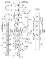
- 5A is a schematic side view of the production line 30 of the package body 21, FIG. 5B is a view taken along the line BB in FIG. 5A, and FIG. 5C is a view taken along the line CC in FIG. 5A. is there.
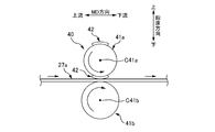
- FIG. 3 is a schematic side view of a perforation forming device 40.
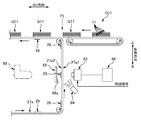
- FIG. 2 is a schematic side view of a labeler device 50.
- FIG. 2 is a schematic side view of an inspection device 60.
- FIG. It is an image figure of the plane image which plane image data shows.
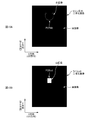
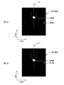
- FIG. 10A is a binarized image of the perforation, and
- FIG. 10B is a binarized image of the label 28.
- a method for producing a package in which at least one sanitary article is packaged by a packaging sheet The packaging sheet that packages the sanitary article has a portion that becomes an opening / closing lid after opening by being cut along the line of weakness when opened, and a portion corresponding to the line of weakness in the packaging sheet is opened
- a label that sometimes becomes a knob is joined so that it can be fixed with the opening and closing lid closed after opening
- the manufacturing method includes: Transporting a plurality of the sanitary articles along a transport direction, transporting the sanitary articles adjacent to each other in the transport direction with a gap therebetween; Forming the line of weakness in a portion corresponding to the sanitary article in a continuous body of the packaging sheet continuous in the transport direction; Bonding the label for each line of weakness to the continuum of the packaging sheet; Determining pass / fail of the bonding position of the label in the packaging sheet based on the relative positional relationship between the weak line and the label in the continuum of the packaging sheet; Wrapping the sanitary article in the continuum of the packaging sheet by
- the determination of pass / fail is performed based on image data generated by imaging the weak line and the label in the continuum of the packaging sheet. Therefore, the pass / fail determination can be performed accurately.
- a method of manufacturing a package for such a hygiene article The imaging is preferably performed before the wrapping.
- a continuum of packaging sheets is imaged before wrapping, and the image data captured at such timing is in a state in which the continuum of packaging sheets is substantially flat.
- the relative positional relationship between the line of weakness and the label is shown. Therefore, this relative positional relationship is extremely accurate. And since the determination of the pass / fail of the bonding position of the label is performed based on the relative positional relationship shown correctly, the determination accuracy of the pass / fail can be improved.
- the continuous body of the packaging sheet has, as three directions orthogonal to each other, a continuous direction in which the continuous body continues, a thickness direction, and a width direction,
- the packaging sheet is a sheet through which the other side can be seen through from one side in the thickness direction,
- the imaging is performed by a camera, and the camera images the surface of the one side of the continuous body of the packaging sheet, It is desirable that a light-shielding member having a non-ground surface is provided so as to face the other surface, which is the surface opposite to the one surface captured by the camera.
- the image of the image data obtained by imaging one side of the continuum of packaging sheets with a camera includes a continuum of packaging sheets.
- an irrelevant member positioned on the other side in the thickness direction may be reflected, and this reflection causes an erroneous determination in the above pass / fail determination.
- a light shielding member having a non-ground surface is provided so as to face the other surface which is the opposite surface of the one surface of the continuum of the packaging sheet,
- a non-ground prevents reflection of a member located on the other side of the light shielding member. Therefore, it is possible to prevent a decrease in accuracy of pass / fail judgment that can occur when a continuous body of packaging sheets that can be seen through is used.
- a method of manufacturing a package for such a hygiene article In determining pass / fail, based on the image data, a value corresponding to the size of the interval between the predetermined portion of the weak line and the predetermined portion of the label is used as information indicating the relative positional relationship. Calculate When the calculated value is included in a predetermined allowable range, it is desirable to determine that the value is acceptable.
- a value corresponding to the size of the gap between the predetermined portion of the weak line and the predetermined portion of the label is used as information indicating the relative positional relationship. Make a decision. Therefore, this determination can be performed accurately and reliably.
- a method of manufacturing a package for such a hygiene article It has a target value related to the interval in advance, Obtaining a difference between the calculated value and the target value; It is desirable to change at least one of the formation position of the weak line and the joining position of the label in the transport direction so that the obtained difference is reduced.
- At least one of the position where the weak line is formed and the position where the label is joined is changed in the transport direction so that the above-described difference is reduced. Therefore, it can adjust reliably in the direction in which the determination of the pass / fail of the bonding position of the label is acceptable.
- a method of manufacturing a package for such a hygiene article In determining the pass / fail, When generating the first binarized image by binarizing the image data based on the first threshold value, the first binarized image is specified by one of the two values. Binarization processing is performed so that the image includes the imaging portion of the weak line on the image indicated by the image data, When the image data is binarized based on a second threshold to generate a second binarized image, the second binarized image is specified by one of the binaries.
- Binarization processing is performed so that the image includes the imaging portion of the label on the image indicated by the image data, Based on both the position of the imaging portion of the weak line in the first binarized image and the position of the imaging portion of the label in the second binarized image, the weak line and the label It is desirable to generate information indicating the relative positional relationship.
- a first binarized image specialized in specifying the position of the imaging portion of the weak line is generated based on the first threshold, and the second Based on the threshold value, a second binarized image specialized for specifying the position of the imaging portion of the label is generated.
- the information which shows the relative positional relationship of a weak line and a label is produced
- a method of manufacturing a package for such a hygiene article The line of weakness is not set in the portion that becomes the hinge of the opening / closing lid in the continuous body of the packaging sheet,
- the fragile line is formed such that a portion of the fragile line that becomes the tip of the opening / closing lid is located on one side in the transport direction from the part that becomes the hinge,
- the label is joined to the continuum of the packaging sheet so that the label covers the portion that becomes the tip of the weakened line, It is preferable that the pass / fail judgment is made based on a relative positional relationship between a portion of the weakened line that becomes the tip of the opening / closing lid and the label.
- the label is joined across the portion of the weak line that becomes the tip of the opening / closing lid in the transport direction, whereby the label is pinched at the time of opening.
- it functions as a fixing member that fixes the opening / closing lid in a closed state after opening. Therefore, the part which becomes the front-end
- cover is an important part in the meaning that the said function is exhibited reliably.
- the portion that becomes the tip of the opening / closing lid in the weak line is the target of attention in the relative positional relationship, and thereby the portion that becomes the tip of the opening / closing lid and the label
- the relative positional relationship of can be calculated accurately. Therefore, what a label performs said function can be determined to be a pass.
- a method of manufacturing a package for such a hygiene article The line of weakness is not set in the portion that becomes the hinge of the opening / closing lid in the continuous body of the packaging sheet,
- the fragile line is formed such that a portion of the fragile line that becomes the tip of the opening / closing lid is located on one side in the transport direction from the part that becomes the hinge,
- the label is joined to the continuous body of the packaging sheet so that the label crosses the portion that becomes the tip of the line of weakness in the transport direction,
- the label has a design, In the determination, it is preferable to determine that the pass is passed when a predetermined portion of the weak line overlaps the symbol.
- the total light transmittance of the packaging sheet is preferably 60% or more.
- the total light transmittance of the packaging sheet is 60% or more. Therefore, the sanitary article inside the package can be easily visually recognized from the outside of the package. As a result, the design and the like drawn on the sanitary article can be shown as if they were the design of the package, and the degree of freedom in design of the package can be increased.
- the sanitary article is an individual packaged product in which absorbent articles are individually packaged,
- In the transport a plurality of the individually packaged products are transported in the transport direction in a stacked state,
- In the wrapping it is desirable to wrap the plurality of the individually packaged products in the stacked state with a continuous body of the packaging sheets.
- An apparatus for manufacturing a package in which at least one sanitary article is packaged by a packaging sheet The packaging sheet that packages the sanitary article has a portion that becomes an opening / closing lid after opening by being cut along the line of weakness when opened, and a portion corresponding to the line of weakness in the packaging sheet is opened A label that sometimes becomes a knob is joined so that it can be fixed with the opening and closing lid closed after opening,
- the manufacturing apparatus includes: An apparatus for conveying a plurality of the hygiene articles along a conveying direction, wherein the apparatus conveys the sanitary articles adjacent to each other in the conveying direction with a gap therebetween; An apparatus for forming the line of weakness in a portion corresponding to the sanitary article in the continuous body of the packaging sheet that is continuous in the transport direction; An apparatus for joining the label for each line of weakness with respect to the continuous body of the packaging sheet; An apparatus for determining pass / fail of the bonding position of the label in the packaging sheet, based on the relative positional relationship between the weak line and the label in the continuum of the packaging
- the determination of pass / fail of the label joining position is performed based on the relative positional relationship between the weak line and the label. Therefore, it is possible to appropriately determine whether the label joining position is acceptable.
- the determination of pass / fail is performed based on image data generated by imaging the weak line and the label in the continuum of the packaging sheet. Therefore, the pass / fail determination can be performed accurately.
- the manufacturing method and the manufacturing apparatus 30 of this embodiment manufacture the packaging body 21 of sanitary goods.
- the hygiene article is an individual package 11 in which the panty liner 1 as an example of an absorbent article is individually packaged, and the package 21 of the hygiene article includes the individual packages 11, 11,.
- a plurality of stacked sheets are packaged by the packaging sheet 27.
- FIG. 1A is a schematic plan view of the panty liner 1
- FIG. 1B is a cross-sectional view taken along the line BB in FIG. 1A
- FIG. 1C is a schematic plan view of the individual packaged article 11 of the panty liner 1
- FIG. 1D is a state where the individual packaged article 11 of the panty liner 1 of FIG. 1C is unpacked, that is, the individual packaging sheet 7 and the panty liner. It is a schematic plan view of the unfolding state which opened both of 1 together.
- a panty liner 1 includes an absorbent body 2 formed by laminating liquid absorbent materials such as pulp fibers in a predetermined shape, and a liquid permeable top sheet 3 from both sides in the thickness direction. It is a thin sheet-like member covered with a liquid-impermeable back sheet 4 and its planar shape is, for example, a substantially hourglass shape.
- a non-slipping adhesive 5 used for fixing to the undergarment is applied to the surface of the back sheet 4 that forms the non-skin side surface of the liner 1.
- a release sheet 6 is provided so as to cover the slip-off preventing adhesive 5.
- the release sheet 6 is firmly joined to an individual packaging sheet 7 to be described later, and when the liner 1 is used, the release sheet 6 is separated from the adhesive 5 for preventing the liner 1 together with the individual packaging sheet 7. It is peeled off quickly.
- the individual packaging sheet 7 provided for individual packaging of the liner 1 is, for example, a rectangular sheet in plan view. And in the state which piled up the panty liner 1 on the packaging sheet 7, the planar size of the sheet 7 is made into the planar size which protrudes outward from at least three sides of the four sides of the panty liner 1. .
- the individual packaging sheet 7 protrudes on both sides in the width direction of the panty liner 1 and on one side in the longitudinal direction, but on the other side in the longitudinal direction, Is popping out of the individual packaging sheet 7.
- the individual packaging sheet 7 three fold lines of a first fold line, a second fold line, and a third fold line as an example of a plurality of fold lines are set at different positions in the longitudinal direction. . Then, the individual wrapping sheet 7 together with the liner 1 is folded three times in the longitudinal direction in the order close to the portion where the liner 1 protrudes, that is, in the order of the first, second and third fold lines. In the state, a joining portion 7s such as a seal portion is provided at a predetermined portion or the like that forms an outer contour. And the individual packaging sheet 7 is sealed in such a state that the liner 1 is accommodated by the joining portion 7s, thereby forming the individual packaging product 11 of FIG. 1C.
- a joining portion 7s such as a seal portion is provided at a predetermined portion or the like that forms an outer contour.
- this individual package 11 is a vertically long member with the dimension L11 of the direction orthogonal to the folded direction longer than the dimension W11 of the folded direction.
- the direction of the long dimension L11 is referred to as “longitudinal direction”
- the direction of the short dimension W11 is referred to as “width direction”.
- the direction orthogonal to both the longitudinal direction and the width direction is the thickness direction of the individually packaged product 11.
- FIG. 2A to FIG. 2C are explanatory diagrams of a package 21 formed by further packaging such individual packages 11, 11.
- 2A is a schematic perspective view of the package body 21
- FIG. 2B is a schematic plan view of the package body 21
- FIG. 2C is a cross-sectional view taken along the line CC in FIG. 2B.
- the package body 21 includes an individual package product group G11 in which six individual package products 11, 11,... Are stacked in the thickness direction, and a packaging sheet 27 that packages the individual package product group G11.
- a colorless and transparent resin film is used as the packaging sheet 27, so that the individual individual packaged products 11, 11... Can be seen from the outside of the package 21. If the total light transmittance of the packaging sheet 27 (see JIS K 7105 measurement method A) is 60% or more, the individual packaged items 11, 11. Accordingly, the design of each individual package 11 can be seen as if it is the design of the package 21, which is preferable.
- the packaging sheet 27 is not limited to a colorless and transparent resin film.
- the packaging sheet 27 may be colored, translucent, opaque, non-woven fabric, woven fabric, or a material other than resin.
- the packaging sheet 27 before packaging is, for example, a rectangular sheet, and its planar size is larger than the planar size of the individual packaged product group G11.
- the packaging body 21 of FIG. 2A is formed when this packaging sheet 27 packages the individual packaged goods group G11 as follows. First, in a state where the individual packaged product group G11 is placed at the approximate center of the plane of the packaging sheet 27 in FIG. 3A, the respective portions 27ew and 27ew of the packaging sheet 27 projecting sideways from both sides in the width direction of the individual packaged product 11 are shown. As shown in FIG. 3B, the portions 27ew and 27ew are overlapped with each other above the individually packaged product group G11 to form the packaging sheet 27 in a cylindrical shape.
- the packaging sheets 27 are fixed in a cylindrical shape by joining the parts 27ew and 27ew with an adhesive, thereby fixing the individual packaged product group G11 in a state of being wrapped by the packaging sheet 27. And as shown to FIG. 3B and FIG. 3C, each opening part 27ek and 27ek of the both ends of the cylinder axial direction C27 of this cylindrical packaging sheet 27 are sealed by welding etc., respectively, and sealing part 27s and 27s are formed. Thus, the package 21 of the individually packaged product group G11 is formed.
- the package 21 has a substantially rectangular parallelepiped shape. And the longitudinal direction of the package body 21 faces the same direction as the longitudinal direction of the individual package products 11, 11..., And the width direction of the package body 21 is the same as the width direction of the individual package products 11, 11. Similarly, the thickness direction of the package 21 is the same as the thickness direction of the individually packaged items 11, 11.
- the outer shape of the packaging sheet 27 in the packaged state as shown in FIG. 2A also has a substantially rectangular parallelepiped shape, that is, the longitudinal direction and the width.
- a pair of plane portions 27A1, 27A1 generally defined by the direction
- a pair of side surface portions 27A2, 27A2 generally defined by the longitudinal direction and the thickness direction
- the pair of end surface portions 27A3 and 27A3 are provided with the sealing portions 27s and 27s, respectively.
- attached with the adhesive agent belong to the plane part 27A1 of the side which cannot be seen.
- a perforation 27M (corresponding to a fragile line) is formed on the flat portion 27A1 of the packaging sheet 27 for opening the packaging sheet 27.
- the perforation 27M is formed in a substantially chevron shape so as to substantially surround the predetermined portion 27cap in the plane portion 27A1.
- the bottom portion 27Mb in the substantially chevron shape is located on the end side in the longitudinal direction of the flat surface portion 27A1, and the top portion 27Mt in the substantially chevron shape (corresponding to “the portion that becomes the front end portion of the opening / closing lid”) is the central side in the longitudinal direction. Is located.
- the perforation 27M is substantially not formed in the portion corresponding to the bottom portion 27Mb in the flat portion 27A1. Further, a rectangular label 28 is joined by an adhesive (not shown) so as to cover the substantially mountain-shaped top portion 27Mt of the perforation 27M.
- the packaging sheet 27 is opened as follows. First, as shown in FIGS. 2A and 2B, the portion 28 p of the perforation 27 ⁇ / b> M that protrudes from the top portion 27 ⁇ / b> Mt to the center side in the longitudinal direction is pinched and pulled away from the packaging sheet 27. Then, the perforation 27M is gradually cut from the apex 27Mt as a starting point, and the cutting range is expanded to the end side in the longitudinal direction. And finally, as shown in FIG. 4, it reaches the bottom portion 27Mb having a substantially chevron shape, but since the perforation 27M is not formed in the bottom portion 27Mb, the cutting stops at the bottom portion 27Mb.
- the predetermined portion 27cap surrounded by the substantially chevron-shaped perforations 27M is separated from the packaging sheet 27 except for the portion corresponding to the bottom portion 27Mb, and the packaging sheet 27 corresponds to the predetermined portion 27cap.
- a substantially chevron shaped outlet 27h is formed.
- the predetermined portion 27cap is an open / close lid 27cap that can be opened and closed with the bottom 27Mb as a hinge.
- the label 28 is mainly bonded to the predetermined portion 27cap of the packaging sheet 27 with an adhesive, whereby the label 28 also opens and closes integrally with the opening / closing lid 27cap after opening.
- the part 28p of the label 28 protrudes outward from the opening / closing lid 27cap, and can be rejoined to the portion 27ha around the take-out port 27h of the packaging sheet 27 by the adhesive of the protruding portion 28p. It has become.
- the user of the packaging body 21 takes out the individual packaged product 11 from the packaging sheet 27, the user can fix the takeout opening 27h closed with the open / close lid 27cap any number of times.
- the individual packaged items 11, 11 can be carried around, for example, in a bag while maintaining good hygiene.
- FIG. 5A is a schematic side view of the production line 30.
- 5B is a BB arrow view in FIG. 5A
- FIG. 5C is a CC arrow view in FIG. 5A.
- 5B and 5C are diagrams mainly illustrating a state in which the continuous body 27a of the packaging sheet 27, the individual packaged product group G11, and the like gradually change to the package body 21, and therefore FIG. And in FIG. 5C, each apparatus 40, 50, 60, 70 of the production line 30 is not illustrated.
- the production line 30 includes a transport device 32 such as a belt conveyor or a transport roller, as shown in FIGS. 5A and 5C.
- the transport device 32 transports the individual packaged product group G11 in which the six individual packaged products 11, 11... Are stacked in the thickness direction at a predetermined transport pitch PG11 along the transport direction.
- the conveyance direction is referred to as “MD direction”, and the direction orthogonal to the MD direction is referred to as “CD direction”.
- the width direction of the individual package product 11 is along the CD direction, and thereby the individual package product group G11 is conveyed in a state in which the longitudinal direction of each individual package product 11 is along the MD direction.
- the CD direction corresponds to the “crossing direction intersecting the transport direction” according to the claims.
- a continuous body 27 a of a packaging sheet 27 continuous in the MD direction is transported in the MD direction.
- the perforation forming device 40 and the labeler device 50 are arranged in this order from the upstream in the MD direction to the downstream at a predetermined position in the MD direction. Therefore, when passing through the perforation forming device 40, a substantially chevron-shaped perforation 27M is formed in a portion corresponding to the individually packaged product group G11 in the continuous body 27a, and the labeler device 50 is When passing, a rectangular label 28 is bonded to the continuous body 27a for each substantially mountain-shaped perforation 27M.
- an inspection device 60 is arranged at a downstream position in the MD direction of the labeler device 50.
- the inspection device 60 inspects the joining position of the label 28 in the continuous body 27 a of the packaging sheet 27.
- the inspection result is displayed on a display unit (not shown) such as a monitor to notify the operator.
- the continuous body 27a of the packaging sheet 27 that has passed through the inspection device 60 joins the transport device 32 that transports the individually packaged product groups G11, G11,. And the continuous body 27a of the packaging sheet 27 which merged with the conveyance apparatus 32 in the confluence
- G11, G11... Are substantially integrated and conveyed along the MD direction. And it passes the bending guide member 70 arrange
- the end portions 27 aew and 27 aew in the CD direction of the continuous body 27 a of the packaging sheet 27 are bent.
- the continuous body 27a of the packaging sheet 27 is formed into a cylindrical shape by overlapping the end portions 27aew and 27aew on the individual packaged product group G11, and the adhesive applied to the end portions 27aew and 27aew.
- the end portions 27 aew and 27 aew are joined to each other by the agent, and the continuous body 27 a is fixed in a cylindrical shape. And thereby, the continuous body 27a will be in the state which wrapped the individual packaged goods group G11.
- coating of said adhesive agent is made
- the continuous body 27a of the cylindrical packaging sheet 27 passes through the sealing device 80 downstream in the MD direction. And during the passage, the sealing device 80 seals the continuous body 27a of the cylindrical packaging sheet 27 that encloses the individual packaged goods group G11, and the individual packaged goods group in the continuous body 27a of the packaging sheet 27.
- a sealing portion 27s is formed in a portion between G11 and G11.
- FIG. 6 is a schematic side view of the perforation forming device 40.
- the perforation forming apparatus 40 has, for example, a pair of upper and lower rolls 41a and 41b. Each of the rolls 41a and 41b rotates around the rotation axes C41a and C41b along the CD direction, and thereby rotates so as to send the continuous body 27a of the packaging sheet 27 downstream in the MD direction.
- the rotation drive source is a servo motor.
- one roll 41a of the pair of upper and lower rolls 41a and 41b is a perforation blade roll 41a having a substantially chevron-shaped perforation blade 42 corresponding to the perforation 27M on the outer peripheral surface
- the other roll 41b is an anvil roll 41b which receives the perforation edge 42 with a smooth outer peripheral surface.
- the formation pitch P27M of the perforations 27M is substantially the same as the transport pitch PG11 of the individual packaged product group G11 described above, whereby the perforations 27M are formed corresponding to each individual packaged product group G11. .
- the realization of the formation pitch P27M and the conveyance pitch PG11 is achieved by aligning the arrangement pitch of the perforated blades 42 in the circumferential direction of the upper roll 41a to the same value as the conveyance pitch PG11. For example, in this example, since the total length of the rotation trajectory for one rotation of the perforation blade 42 is twice the conveyance pitch PG11, the perforation blade 42 is positioned at two positions in the circumferential direction of the perforation blade roll 41a. Are provided at equal pitches.
- each roll 41a, 41b is made to rotate substantially synchronizing with the conveyance speed value of the continuous body 27a of the packaging sheet 27, and, thereby, in the position of the perforation blade 42 of the perforation blade roll 41a.
- Both the peripheral speed value (m / second) and the peripheral speed value (m / second) of the outer peripheral surface of the anvil roll 41b are respectively the conveyance speed value (m / second) in the MD direction of the continuous body 27a of the packaging sheet 27. It is almost complete. Therefore, when the perforation blade 42 hits the continuous body 27a of the packaging sheet 27, the perforation 27M is smoothly formed on the continuous body 27a of the packaging sheet 27 by the perforation blade 42.
- Such synchronization is realized by position control of a servo motor (not shown) that drives each of the rolls 41a and 41b by an appropriate controller based on the synchronization signal, which will be described later.
- the substantially chevron shape of the perforation 27M is formed in a state facing the upstream side in the MD direction, and thereby the top portion 27Mt of the substantially chevron shape of the perforation 27M is It forms the upstream end in the MD direction of the perforation 27M.
- FIG. 7 is a schematic side view of the labeler device 50.
- the labeler device 50 is a device 50 that joins the label 28 to each perforation 27M formed in the continuous body 27a of the packaging sheet 27 (see FIG. 5B).
- the label 28 is carried in the form of a label paper roll R28L in which the label paper 28L is wound up in a roll shape.
- the label paper 28L is also called a so-called sticker paper, and has a long strip-shaped release paper 28S (also referred to as a separator), and a plurality of labels 28, 28... attached.
- the labels 28, 28... Are attached side by side at a predetermined attaching pitch P0 in the longitudinal direction of the strip-like release paper 28S. Then, the labeler device 50 peels the label 28 on the most downstream side in the feeding direction from the release paper 28S in order while feeding the label paper 28L, and joins it to the continuous body 27a of the packaging sheet 27.
- the labeler device 50 includes a reel 51 for feeding out the label paper 28L from the label paper roll R28L, and a take-up reel 52 for taking up the release paper 28S from which the label 28 has been peeled off.
- a mechanism 52 that peels the label 28 from the label paper 28L and joins it to the continuous body 27a of the packaging sheet 27 is provided at a predetermined position in the feeding path of the label paper 28L set between the reels 51 and 52. It has been.
- the mechanism 52 has a knife edge member 53 that is pointed in the feeding direction.
- the feeding path of the label paper 28L is generally reversed at the pointed tip 53e of the knife edge member 53.
- the label paper 28L passes through the position of the tip 53e of the knife edge member 53, only the release paper 28S is reversed, and the label 28 cannot be reversed and goes straight, so that the label 28 is released. It is peeled from 28S. Then, the peeled label 28 is sent between a pair of upper and lower pinch rolls 54a and 54b located immediately before, and between these pinch rolls 54a and 54b, a continuous body 27a of the packaging sheet 27 is also provided. It is conveyed along the MD direction. Therefore, the label 28 is overlapped and joined to the upper surface of the continuous body 27a of the packaging sheet 27 at the positions of the pinch rolls 54a and 54b.
- the sticking pitch P0 of the label 28 on the release paper 28S and the joining pitch P28 of the label 28 on the continuous body 27a of the packaging sheet 27 are not equal to each other,
- the joining pitch P28 is larger than the sticking pitch P0.
- the feeding speed value (m / second) of the feeding operation of the label paper 28L is set to the continuous body 27a of the packaging sheet 27. It is necessary to join at a value substantially equal to the conveyance speed value (m / sec). Therefore, the labeler device 50 joins the label 28 to the continuous body 27a of the packaging sheet 27 while intermittently feeding out the label paper 28L.
- the label 28 is joined to the continuous body 27a while feeding out the label paper 28L with the feeding speed value being substantially the same as the conveyance speed value of the continuous body 27a of the packaging sheet 27, and the joining pitch P28 is pasted.
- the inconsistency with the attached pitch P0 is dealt with by providing a feeding stop state between the feeding operations by an amount corresponding to the joining pitch P28 being longer than the pasting pitch P10.
- the feeding amount per one time of such intermittent feeding operation is preset to the same value as the above-mentioned sticking pitch P28. Further, the resumption of the feeding operation from the stopped state is performed based on the synchronization signal, which will be described later.
- FIG. 8 is a schematic side view of the inspection apparatus 60.
- the inspection device 60 inspects the bonding position of the label 28.
- the inspection is performed based on the relative positional relationship between the bonding position of the label 28 and the formation position of the perforation 27M. Then, as an inspection result, the result of pass / fail determination of the joining position of the label 28 is displayed on an appropriate display unit such as a monitor, etc., to notify the operator.
- the inspection device 60 includes a camera 62 among a camera 62 provided at a predetermined position between the labeler device 50 and the merging position Pj and both surfaces 27a1 and 27a2 of the continuous body 27a of the packaging sheet 27.
- a camera 62 among a camera 62 provided at a predetermined position between the labeler device 50 and the merging position Pj and both surfaces 27a1 and 27a2 of the continuous body 27a of the packaging sheet 27.
- the camera 62 is, for example, a CCD (charge coupled device) camera.
- the camera 62 is disposed so as to face the surface 27a1 of the continuum 27a of the packaging sheet 27 where the label 28 is not joined among the both surfaces 27a1, 27a2.
- the camera 62 images the continuous body 27a of the passing packaging sheet 27 from the surface 27a1 on which the label 28 is not bonded, generates plane image data of the surface 27a1, and generates an image processing unit. 66.
- Such an imaging operation is performed, for example, for each portion 27au corresponding to one packaging body 21 in the continuous body 27a of the packaging sheet 27.
- the portion 27au corresponding to one packaging body 21 is described below. Is also referred to as “unit packaging sheet 27au”.
- the imaging operation for each unit packaging sheet 27au is performed based on the synchronization signal.
- the synchronization signal is a signal for operating the devices 32, 34, 40, 50, 60, 80, 90 belonging to the production line 30 in conjunction with each other, and each of the devices 32, 34, 40 is operated.
- 50... Are signals in which unit signals corresponding to processing operations to be performed on one package 21 are repeatedly and continuously output. Therefore, when one unit signal is output, each device 32, 34, 40, 50... Performs a processing operation to be performed on one package 21. For example, the positions of the servo motors of the rolls 41a and 41b of the perforation forming device 40 are controlled so that the rolls 41a and 41b are rotated by half for each unit signal.
- a perforation 27M is formed for each unit packaging sheet 27au.
- a rotation angle signal having each rotation angle value of 0 ° to 360 ° can be exemplified.
- the synchronization signal is a rotation angle value of 0 ° to 360 ° for one cycle.
- the rotation angle value of 0 ° to 360 ° is a signal that is repeatedly output. In this example, this signal is used as a synchronization signal.
- the position of the servomotor of the take-up reel 52 of the labeler device 50 is also controlled based on the synchronization signal. That is, every time a predetermined rotation angle value is output in the unit signal of the synchronization signal, the stopped feeding operation is restarted with the output of the rotation angle value as a starting point, and the same value as the above-mentioned sticking pitch P0 is supplied. The feeding operation is stopped when the amount is fed out. And thereby, the labeler apparatus 50 joins the label 28 for every unit packaging sheet 27au, ie, every perforation 27M, as processing operation
- the rotation angle value that defines the starting point of the feeding operation is set in advance in the controller of the labeler device 50 as a set value.
- the camera 62 is disposed at a position between the labeler device 50 and the merge position Pj. Therefore, the camera 62 images the continuous body 27a of the packaging sheet 27 in a substantially planar state before wrapping the individual packaged goods group G11. In the plane image data imaged and generated in the substantially planar state, the relative positional relationship between the perforation 27M and the label 28 is accurately shown. Therefore, it is possible to accurately perform the pass / fail determination of the joining position of the label 28 based on the planar image data thereafter.
- the illumination member 64 is an appropriate light such as a white LED light or a fluorescent lamp, and the type of the light source is appropriately selected according to the imaging situation on the spot. Further, as described above, the illumination member 64 is arranged so as to illuminate the surface 27a1 captured by the camera 62 among the both surfaces 27a1, 27a2 of the continuous body 27a of the packaging sheet 27. Therefore, in this example, the camera 62 receives the reflected light reflected from the surface 27a1 to which the label 28 is not bonded out of the both surfaces 27a1, 27a2 of the continuous body 27a of the packaging sheet 27, thereby receiving the same surface 27a1. Take an image.
- the continuous body 27a of the packaging sheet 27 is colorless and transparent. Therefore, even from the surface 27a1 to which the label 28 is not joined, the label 28 can be sufficiently seen through the continuum 27a of the packaging sheet 27, so that the label 28 can be seen without any problem.
- the images are taken together with the perforations 27M of the continuous body 27a of the packaging sheet 27.
- the image processing unit 66 includes an appropriate computer as a main body and includes a processor and a memory.
- the processor reads out and executes various processing programs stored in advance in the memory, thereby performing various arithmetic processes.
- a second binarization processing program for generating a binarized image of the label 28 (corresponding to the second binarized image) from the data is stored in advance.
- a calculation processing program for calculating information on the relative positional relationship between the formation position of the perforation 27M and the bonding position of the label 28 based on the binarized image of the perforation 27M and the binarized image of the label 28 An acceptance / rejection determination processing program for determining acceptance / rejection of the joining position of the label 28 based on the information is also stored in advance.
- the image processing unit 66 first generates a binarized image of the perforation 27M and a binarized image of the label 28 from the planar image data. Calculation processing for performing each processing and calculating information on the relative positional relationship between the formation position of the perforation 27M and the bonding position of the label 28 based on the binarized image of the perforation 27M and the binarized image of the label 28 Further, a pass / fail determination process is performed for determining pass / fail of the joining position of the label 28 based on the information.
- FIG. 9 is an image diagram of a planar image captured and recorded, that is, a planar image indicated by planar image data.
- the planar image is captured with the CD direction as the X direction and the MD direction as the Y direction, and the planar image is captured as an entire image of the unit packaging sheet 27au.
- Such a planar image is an aggregate of a large number of pixels arranged in a grid at a predetermined pitch based on a predetermined resolution in both the X direction and the Y direction.
- the planar image is composed of a plurality of pixels arranged in a straight line in the X direction at a predetermined pitch and arranged in a plurality of rows at a predetermined pitch in the Y direction.
- the plane image data has color information corresponding to each pixel. In this example, since the plane image data is grayscale, each pixel has only brightness as color information.
- each pixel corresponding to the highly reflective region in the unit packaging sheet 27au becomes bright, the brightness of the pixel is high, but on the other hand, it corresponds to the region with low reflectivity. Since each pixel becomes dark, the lightness of the pixel has a low value.
- the reflectivity of the portion of the unit packaging sheet 27au where the perforation 27M is formed is higher than that of the portion where the perforation 27M is not formed. Therefore, by paying attention to pixels whose brightness is not less than the first threshold, it is possible to specify the pixels in the region A27M where the perforation 27M is imaged on the planar image in FIG.
- the reflectivity of the portion of the unit packaging sheet 27au where the label 28 is bonded is higher than that of the portion where the label 28 is not bonded. Therefore, by paying attention to the pixels whose brightness is the second threshold value or more, it is possible to specify the pixels in the area A28 where the label 28 is captured on the planar image in FIG.
- each of the first threshold value and the second threshold value is stored in advance in the memory.
- the first threshold value is set higher than the second threshold value.
- the present invention is not limited to this, and if the height relationship of reflectivity is the reverse of the above, the height relationship between the first threshold value and the second threshold value is also reversed.
- the binarized image of the perforation 27M in FIG. 10A is generated as follows. First, among the pixels related to the planar image in FIG. 9, a pixel having a brightness equal to or higher than the first threshold is “1” which is one of the two values (for example, 0 and 1) in the binarized image in FIG. 10A. On the other hand, pixels having brightness less than the first threshold value are assigned to the black image specified by the other value “0”. This is performed for all the pixels of the planar image. Thereby, among the pixels in the planar image of FIG. 9, the region A27M where the perforation 27M is imaged is included in the white image in the binarized image as shown in FIG. 10A, and the other portions are black. As a result, the binarized image of the perforation in FIG. 10A is generated.
- the binarized image of the label 28 in FIG. 10B is generated as follows. First, among the pixels related to the planar image of FIG. 9, pixels of brightness included in a numerical range that is greater than or equal to the second threshold value and less than the first threshold value are represented by binary values (for example, 0 and 1) in the binarized image of FIG. 10B. One of the values is assigned to a white image specified by “1”, and on the other hand, pixels having brightness outside the above numerical range are assigned to a black image specified by the other value “0”. This is performed for all the pixels of the planar image. Thereby, among the pixels in the planar image of FIG. 9, the area A28 where the label 28 is imaged is included in the white image in the binarized image as shown in FIG. 10B, and the other parts are black images. As a result, the binarized image of the label 28 in FIG. 10B is generated.
- the image processing unit 66 proceeds to the calculation process of the relative positional relationship information.
- the image processing unit 66 proceeds to the calculation process of the relative positional relationship information.
- the relative positional relationship information is calculated.
- the top portion 27Mt (corresponding to the “predetermined portion of the weak line”) of the perforation 27M is referred to, and the label
- the end portion 28ed (corresponding to the “predetermined portion of the label”) on the downstream side in the MD direction of the label 28 is referred to as a representative of the joining position 28, and further, as an example of relative positional relationship information
- the distance D between the position of the top portion 27Mt of the substantially chevron shape of the perforation 27M and the position of the downstream end portion 28ed in the MD direction of the label 28 (corresponding to "value corresponding to the size of the distance") I want to ask.
- the position of the top 27Mt of the perforation 27M is obtained as the pixel position P27Mt at which the Y coordinate is minimum in the white image of the binarized image of the perforation 27M in FIG. 10A, and the downstream of the label 28 in the MD direction.
- the position of the side end portion 28ed is obtained as the pixel position P28ed at which the Y coordinate is maximum in the white image of the binarized image labeled 28 in FIG. 10B. Therefore, the image processing unit 66 changes the size of the interval D as the information on the relative positional relationship from the maximum value of the Y coordinate in the white image of the binarized image of the label 28 to the binarized image of the perforation 27M.
- the minimum value of the Y coordinate in the white image is subtracted.
- the image processing unit 66 proceeds to pass / fail determination processing.
- the pass / fail determination process the pass / fail of the joining position of the label 28 is determined by comparing the size of the interval D with a predetermined allowable range.
- the allowable range is stored in the memory in advance in the form of numerical data. For example, in this example, as shown in FIG. 11, since the length of the label 28 in the MD direction is 15 mm, the permissible range is set to a range of 7 m ⁇ 3 mm, that is, a range of 4 mm to 10 mm. If it is within this allowable range, the perforation 27M can be smoothly cut and opened by pinching and pulling up the label 28. After opening, the opening / closing lid 27cap formed accompanying the opening. Can be reliably re-joined to the portion 27ha around the outlet 27h by the adhesive of the label 28 (FIG. 4).
- the image processing unit 66 determines that “the bonding position of the label 28 is acceptable”. On the other hand, if it is out of the allowable range, it is determined that “the bonding position of the label 28 is rejected”. Then, the image processing unit 66 transmits the determination result to the display unit, and the display unit displays the screen.
- the plane image is picked up by the surface 27 a 1 (the label 28 is bonded to one side) of the both surfaces 27 a 1 and 27 a 2 of the continuous body 27 a of the packaging sheet 27.
- This is done by the camera 62 disposed opposite the non-facing surface 27a1), and thereby, the surface 27a1 on the one side is imaged.
- a plate-shaped light shield having a groundless surface 68a facing the opposite surface 27a2 of the one surface 27a1 of the continuous body 27a of the wrapping sheet 27, that is, the other surface 27a2.
- a member 68 is preferably provided.
- the light shielding member 68 having the non-ground surface 68a is provided so as to face the other surface 27a2 which is the surface 27a2 opposite to the one surface 27a1 of the continuous body 27a of the packaging sheet 27.
- the groundless surface 68a is a background of the image capturing portion of the perforation 27M and the label 28 on the planar image related to the planar image data, and is a reflection of the member 69 located on the other side of the light shielding member 68.
- the bending guide member 70 has a pair of guide plates 71, 71 arranged in the MD direction downstream of the joining position Pj of the continuous body 27a of the packaging sheet 27 in the MD direction. .
- Each guide plate 71, 71 is disposed on each side of the CD direction.
- the sealing device 80 is a device 80 that forms the continuous body 21a of the package 21 of the individually packaged product group G11 by sealing the continuous body 27a of the cylindrical packaging sheet 27.
- it has a pair of upper and lower rolls 81a and 81b.
- Each of the rolls 81a and 81b rotates around the rotation axes C81a and C81b along the CD direction, and thereby rotates to send the continuous body 27a of the cylindrical packaging sheet 27 downstream in the MD direction.
- the rotation drive source is a servo motor.
- processed portions 82a and 82b for forming the sealing portion 27s are provided so as to protrude.
- the upper and lower rolls 81a and 81b are driven and rotated in synchronization with the conveying operation of the continuous body 27a of the packaging sheet 27 by a servo motor (not shown) as a drive source. Therefore, when the portion between the individual packaged product groups G11 and G11 in the continuous body 27a of the cylindrical packaging sheet 27 passes between the upper and lower rolls 81a and 81b, the processing portion of the upper roll 81a. 82a and the processing part 82b of the lower roll 81b face each other, and a sealing part 27s is formed in the part. And thereby, each individual packaged goods group G11 is accommodated in the continuous body 27a of the packaging sheet 27, and is sealed. That is, the continuous body 21a of the packaging body 21 of the individually packaged product group G11, that is, the one 21a in which a plurality of packaging bodies 21, 21... Are connected in the MD direction is formed.
- the position of the servo motor drive rotation is also controlled based on the synchronization signal. And thereby, whenever the part between individual packaged goods group G11, G11 passes among the continuous bodies 27a of the packaging sheet 27, the process part 82a and the process part 82b oppose the said part. Thus, the upper and lower rolls 81a and 81b are rotated.
- the cutter apparatus 90 is the apparatus 90 which forms the package 21 of the individual packaged goods group G11 by cut
- the rotation drive source is a servo motor.
- One of the upper and lower rolls 91a and 91b is a cutter blade roll 91a having a cutter blade 92 on the outer peripheral surface, and the other roll 91b is a smooth outer peripheral surface and the cutter blade 92. It is an anvil roll 91b which receives. And when the sealing part 27s passes between these rolls 91a and 91b, the cutter blade 92 of the cutter blade roll 91a that rotates is a continuous body of the packaging body 21 at the cutting position Pc included in the sealing part 27s. By hitting 21a, the continuous body 21a of the package body 21 is cut, whereby the package body 21 is formed.
- the position of the servo motor drive rotation is also controlled based on the synchronization signal.
- the cutter blade roll 91a is rotated so that the cutter blade 92 faces the cutting position Pc of the sealing portion 27s.
- the inspection device 60 makes a determination of failure, it is necessary to adjust the relative positional relationship between the formation position of the perforation 27M and the bonding position of the label 28. Such adjustment is performed by the perforation formation device 40. Or by the labeler device 50.
- the perforation forming apparatus 40 can be adjusted as follows. First, the size of the interval D obtained as information on the relative positional relationship is the target value Dm (the median value Dm of 4 mm to 10 mm, which is the allowable range described above, and the “target value related to the interval”). In the case where the distance is larger than 7 mm, the synchronization signal is advanced and input by the phase corresponding to the absolute value of the difference between the size of the interval D and the target value Dm, thereby forming the perforation 27M. If the position is moved relatively downstream in the MD direction, the distance D can be adjusted to be smaller.
- Dm the median value Dm of 4 mm to 10 mm, which is the allowable range described above, and the “target value related to the interval”.
- the synchronization signal is advanced and input by the phase corresponding to the absolute value of the difference between the size of the interval D and the target value Dm, thereby forming the perforation 27M. If the position is moved relatively downstream in the MD direction, the distance D can be
- the synchronization signal is delayed and input by the phase corresponding to the absolute value of the difference between the size of the interval D and the target value Dm.
- the labeler device 50 can be adjusted as follows. First, when the size of the distance D obtained as information on the relative positional relationship is larger than the target value Dm of 7 mm, it corresponds to the absolute value of the difference between the size of the distance D and the target value Dm. If the set value of the rotation angle value that is the starting point of the feeding operation is changed to a larger value by the amount of the phase to be moved, and the start of the feeding operation of the label paper 28L is relatively delayed, the joining position of the label 28 is relatively Therefore, the distance D can be adjusted so that the distance D becomes smaller.
- the rotation angle signal of the rotation angle signal is equivalent to the phase corresponding to the absolute value of the difference between the size of the interval D and the target value Dm. If the set value is changed to a small value and the start of the feeding operation of the label paper 28L is made relatively early, the joining position of the label 28 moves relatively downstream in the MD direction, and as a result, the interval Adjustment can be made in the direction in which the size of D increases.
- Such adjustment may be performed manually by the operator, or may be automatically performed by the perforation forming device 40 or the labeler device 50.
- the operation is as follows.
- the perforation forming device 40 has an advance button and a delay button for adjustment. And while the operator is pushing the advance button, the rolls 41a and 41b are rotated relatively to the rotation by the synchronization signal, and if the advance button is released, the roll is being pushed. The rotation based on the synchronization signal is resumed while maintaining the phase of the advanced amount. On the other hand, while the operator is pressing the delay button, the rolls 41a and 41b rotate with a relatively delay from the rotation due to the synchronization signal. The rotation based on the synchronization signal is resumed while maintaining the delayed phase. Thus, manual adjustment is realized.
- the perforation forming device 40 has a controller (not shown) that controls the servo motor.
- the controller is a computer or a PLC (programmable logic controller).
- the controller controls the position of the rotation of the servo motor by changing the rotation angle value of the synchronization signal by the amount corresponding to the difference between the size of the interval D and the target value Dm, thereby realizing automatic adjustment. Is done.
- the labeler device 50 has a feed start delay button and a feed start delay button for adjustment. Then, the start of the feeding operation can be delayed if the operator changes the set value of the rotation angle value that is the starting point of the feeding operation to a larger value by pressing the feeding start delay button. On the other hand, the start of the feeding operation can be accelerated by changing the set value of the rotation angle value, which is the starting point of the feeding operation, to a smaller value by pressing the button for speeding up the feeding start.
- the labeler device 50 has a controller (not shown) that controls the servo motor of the winding reel 52 described above.
- the controller is a computer or a PLC.
- a synchronization signal is input to the controller.
- the controller changes the set value of the rotation angle value that becomes the starting point of the above-mentioned feeding operation by the amount corresponding to the difference between the size of the interval D and the target value Dm, thereby realizing automatic adjustment. Is done.
- the permissible range of the formation position itself of the perforation 27M in the continuous body 27a of the packaging sheet 27 is substantially the MD direction of the unit packaging sheet 27au. As long as it is located at the end of the frame, it may not be a big problem, and its allowable range is relatively large. Therefore, it is possible to exclude it from the object of quality control.
- the formation position of the perforation 27 ⁇ / b> M may fluctuate more than the allowable range.
- the perforation in the continuous body 27 a of the packaging sheet 27 is possible.
- the formation position of the eyes 27M is also included in the quality control target.
- the inspection device 60 also inspects the formation position of the perforation 27M in the continuous body 27a of the packaging sheet 27 in addition to the above-described relative positional relationship inspection. Hereinafter, this inspection will be described.
- the image processing unit 66 of the inspection apparatus 60 has an allowable range of the formation position of the perforation 27M in the MD direction, for example, based on the cutting position Pc in FIG. That is, in this example, as already described with reference to FIG. 14, the allowable range is set to a range of 30 mm ⁇ 10 mm from the cutting position Pc. And if the formation position of the top part 27Mt which represents the formation position of the perforation 27M is in this permissible range, it is a pass, and if not, it is a failure. Incidentally, also in this case, the median value of the permissible range (20 mm to 40 mm) is the target formation position of the perforation 27M, that is, the target formation position is 30 mm.
- the image processing unit 66 performs the above pass / fail judgment using the Y coordinate of the formation position of the top portion 27Mt obtained in the above-described calculation process of the relative positional relationship information. That is, pass / fail is determined by comparing the Y coordinate of the formation position of the apex 27Mt with the range of the Y coordinate corresponding to the allowable range.
- the imaging operation of the camera 62 is performed based on the synchronization signal, and similarly, the cutting process at the cutting position Pc by the cutter device 90 is also performed based on the synchronization signal. Therefore, it can also be said that the Y coordinate of the plane image data is expressed on the basis of the cutting position Pc, so that the pass / fail judgment can be made based on the above Y coordinate.
- the image processing unit 66 transmits the message to the display unit, and the display unit displays the screen. Further, although it is necessary to adjust the formation position of the perforation 27M, this adjustment is performed using the perforation forming apparatus 40 as follows.
- the Y coordinate of the formation position of the top 27Mt of the perforation 27M obtained by the image processing unit 66 is smaller than the Y coordinate of the target formation position, the Y coordinate of the formation position of the top 27Mt of the perforation 27M.
- the synchronization signal is advanced and input by a phase corresponding to the absolute value of the difference between the Y coordinate of the target formation position and the target formation position, thereby moving the formation position of the perforation 27M relatively downstream in the MD direction.
- the formation position of the perforation 27M can be adjusted to be within the allowable range.
- the Y coordinate of the formation position of the top portion 27Mt of the perforation 27M is larger than the Y coordinate of the target formation position, the Y coordinate of the formation position of the top portion 27Mt of the perforation 27M and the Y coordinate of the target formation position. If the synchronization signal is delayed and input by the phase corresponding to the absolute value of the difference between the perforation 27M and the formation position of the perforation 27M is relatively moved upstream in the MD direction, the perforation of the perforation 27M The formation position can be adjusted in a direction that falls within an allowable range.
- Such adjustment may be performed manually by the operator, or may be automatically performed by the perforation forming device 40. It is obvious that such manual operation and automatic operation can be realized by a method similar to the method using the advance button or the like exemplified as a method for adjusting the relative positional relationship, or the method using the controller. The explanation is omitted.
- the perforation forming device 40 adjusts the formation position of the perforation 27M in this way, the relative positional relationship with the bonding position of the label 28 also changes accordingly, so the relative positional relationship is also adjusted. Will have to.
- the adjustment of the relative positional relationship is performed by the labeler device 50, and the adjustment method is the same as the adjustment method of the relative positional relationship described above. Therefore, the description is omitted.
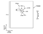
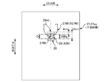
- FIG. 12 is an explanatory diagram of a modification of the present embodiment.
- FIG. 12 is a schematic plan view of the packaging sheet 27 in a developed state on a plane.
- the inspection device 60 uses the distance D between the formation position of the perforation 27M and the bonding position of the label 28 as information on the relative positional relationship between the formation position of the perforation 27M and the bonding position of the label 28. And determining pass / fail based on the distance D.
- the size of the interval D is calculated, the calculation load of the image processing unit 66 of the inspection apparatus 60 increases. Then, the image processing unit 66 easily reaches the limit of the processing capability, which is large when it is desired to increase the number of manufactured packaging bodies 21 per unit time when the production plan of the production line is changed. There is a risk of restrictions.
- the label 28 is also a transparent sheet, and the label 28 is provided with an opaque mark 29 (corresponding to a symbol).
- the heart-shaped mark 29 is provided in a solid color.
- the mark 29 is formed corresponding to the region 28Rg on the label 28 where the top portion 27Mt of the perforation 27M is to be positioned when it is determined that it is acceptable.
- the distance D from the downstream end portion 28ed in the MD direction of the label 28 to the top portion 27Mt of the substantially chevron 27M is 7 mm ⁇ 3 mm, that is, 4 mm to 10 mm.
- the mark 29 is provided over the entire range of 4 mm to 10 mm. More specifically, in this example, the substantially mountain-shaped top portion 27Mt is located at the center position in the CD direction, and at the center position in the CD direction, the heart mark 29 is located downstream of the label 28 in the MD direction. It is formed in the range of 4 mm to 10 mm upstream from the end portion 28ed in the MD direction.
- the top 27Mt is overlapped with the mark 29 as shown in FIG. 12, but in the case of failure, the top 27Mt is not overlapped with the mark 29 and is separated from the mark 29. It will be in the state where it was located. Therefore, it is possible to make a pass / fail judgment by detecting whether or not the top 27Mt is in a state where it overlaps the mark 29. As a result, it is possible to make a pass / fail determination without calculating the size of the interval D.
- the detection of whether or not they are in the above-described overlapping state can be performed by binarizing the planar image data imaged and generated by the camera 62 in FIG. 8 described above.
- the image processing unit 66 selects a pixel having a lightness equal to or higher than a predetermined third threshold among the pixels of the planar image indicated by the planar image data, out of the binary values (for example, 0 and 1)
- the white image specified by one value “1” is allocated to the white image, and the pixel having the lightness less than the third threshold value is allocated to the black image specified by the other value “0”. This is performed for all the pixels of the planar image.
- both the area A27M where the perforation 27M is imaged and the area A29 where the mark 29 is imaged are included in the white image in the binarized image.
- a binary image as shown in FIG. 13A or FIG. 13B is generated.
- the pixel corresponding to the center position Cx in the X direction corresponds to the MD direction.
- a transparent sheet is used not only for the continuous body 27 a of the packaging sheet 27 but also for the label 28. Therefore, the mark 29 of the label 28 can also be imaged by the camera 62 through both the continuous body 27 a of the packaging sheet 27 and the label 28.
- the label 28 is not a transparent sheet, it is difficult to image either the perforation 27M or the mark 29 of the label 28 with the camera 62. Therefore, when applying the method of this modification, it is desirable that the label 28 is a transparent sheet or a translucent sheet such as a translucent sheet. Note that the color of the label 28 may be either colored or colorless.
- the heart-shaped mark 29 is illustrated as an example of the design of the label 28, but the present invention is not limited to this.
- it may be a polygonal mark such as a rectangle, a circular mark, or an illustration.
- the symbol 29 is also a part of the label 28.
- the individual package group G11 is illustrated as an example of the hygiene article, but the present invention is not limited thereto. That is, the sanitary article may be an article that is not individually packaged, or may be an article group in which a predetermined number of articles that are not individually packaged are stacked. Moreover, the absorbent article which concerns on a hygiene article may be other than the panty liner 1, for example, a sanitary napkin, a tampon, a disposable diaper, etc. may be sufficient.
- the surface 27a1 of the continuous body 27a of the packaging sheet 27 to which the label 28 is not bonded is imaged, but the present invention is not limited to this. .
- the surface 27a2 to which the label 28 is bonded may be imaged.
- the camera 62 of the inspection apparatus received the reflected light from the continuum 27a of the packaging sheet 27 and captured one surface 27a1 of the both surfaces 27a1 and 27a2, the present invention is not limited to this.
- the illuminating member 64 illuminates the surface 27a2 opposite to the surface 27a1 captured by the camera 62 of the both surfaces 27a1 and 27a2, thereby transmitting the continuous body 27a of the packaging sheet 27 in the thickness direction.
- the transmitted light may be received, and thereby one of the two surfaces 27a1 and 27a2 may be imaged. That is, the camera 62 and the illumination member 64 may be appropriately arranged so that both the perforation 27M and the label 28 are imaged.
- gray scale data in which the color information of each pixel has only brightness is shown as an example of planar image data, but the present invention is not limited to this.
- the color information of each pixel may be color image data having brightness, hue, and saturation.
- color binarization processing may be performed as the above-described binarization processing.
- the synchronization signal a signal obtained by repeatedly outputting each rotation angle value of 0 ° to 360 ° is illustrated, but the present invention is not limited to this.
- a digital signal in which 8192 digital values from 0 to 8191 are repeatedly output may be used, or the synchronization signal may be a signal in which a pulse signal including a plurality of pulses is repeatedly output.
- the synchronization signal is the rotation angle value signal or the digital signal
- the position control of the servo motor using the synchronization signal is performed with the actual position of the servo motor and the command position indicated by the synchronization signal. This is done by controlling the servo motor so that the deviation is smaller.
- the actual position of the servo motor is measured by an appropriate rotational position detector such as an encoder.
- the controller that controls the servo motor calculates a deviation between the number of pulses of the input synchronization signal and the number of pulses output from the rotational position detector of the servo motor.
- a counter for counting is provided, and the rotation of the servo motor is controlled by the controller so that the deviation becomes small.
- the perforation 27M is illustrated as an example of the weak line, but the present invention is not limited to this.
- a half cut line may be used. In other words, if it is a linear portion having a lower strength than the surrounding portion so that it can serve as a guide line for cutting when it is cut, it can be used as the weak line.
- the position of the top 27Mt of the perforation 27M and the label are represented on behalf of each position.
- the position of the end portion 28ed on the downstream side in the MD direction of 28 is referred to, the position to be referred to is not limited to this.
- the position where the perforation 27M is formed may be referred to, and the position of the end portion 27Med on the downstream side in the MD direction in the perforation 27M may be referred to.
- the position of the end portion 28eu on the upstream side in the MD direction of the label 28 may be referred to.
- the position of the top portion 27Mt of the perforation 27M and the position of the end portion 28ed on the downstream side in the MD direction of the label 28 are respectively set to the minimum value of the Y coordinate of the white image of the perforation 27M and the white of the label 28.
- it was obtained based on the maximum value of the Y coordinate of the image it is not limited to this. For example, you may obtain
- the brightness data of the pixels arranged along the Y direction is differentiated with respect to the Y direction, and the value obtained by the differentiation is compared with an appropriate threshold value. Then, the position of the Y coordinate specified by the comparison is set as the position of the top portion 27Mt of the perforation 27M or the position of the end portion 28ed on the downstream side in the MD direction of the label 28.
Landscapes
- Engineering & Computer Science (AREA)
- Mechanical Engineering (AREA)
- Auxiliary Devices For And Details Of Packaging Control (AREA)
- Containers And Plastic Fillers For Packaging (AREA)
- Packages (AREA)
- Packaging Of Annular Or Rod-Shaped Articles, Wearing Apparel, Cassettes, Or The Like (AREA)
- Labeling Devices (AREA)
- Basic Packing Technique (AREA)
Abstract
Ce procédé de fabrication d'un corps emballé consiste à : transporter une pluralité d'articles pour l'hygiène dans le sens du transport, et à effectuer le transport, de sorte qu'il existe un espace entre des articles pour l'hygiène adjacents dans le sens du transport; à former, au niveau de sections correspondant à des articles pour l'hygiène, des lignes frangibles dans un corps continu d'une feuille d'emballage qui est continue dans le sens du transport; à coller une étiquette par ligne frangible sur le corps continu de la feuille d'emballage; à déterminer si la position de collage de chaque étiquette sur la feuille d'emballage est acceptable à partir des positions relatives de la ligne frangible et de l'étiquette sur le corps continu de la feuille d'emballage; à emballer les articles pour l'hygiène avec le corps continu de la feuille d'emballage par pliage respectif des extrémités du corps continu de la feuille d'emballage dans le sens d'intersection qui croise le sens du transport; à former des parties d'étanchéité dans le corps continu de la feuille d'emballage au niveau des sections entre des articles pour l'hygiène afin de fermer de manière étanche le corps continu de la feuille d'emballage avec les articles pour l'hygiène enroulés à l'intérieur de celui-ci; et à produire des corps emballés formés par l'emballage des articles pour l'hygiène, par découpage du corps continu de la feuille d'emballage au niveau des positions de découpe établies au niveau desdites sections. Pour déterminer ladite acceptabilité, les lignes frangibles dans le corps continu de la feuille d'emballage et les étiquettes sont imagées pour générer des données d'image des lignes frangibles et des étiquettes, et cette acceptabilité est déterminée en fonction des positions relatives des lignes frangibles spécifiées et des étiquettes en fonction des données d'image.
Priority Applications (1)
| Application Number | Priority Date | Filing Date | Title |
|---|---|---|---|
| CN201480037281.6A CN105358437B (zh) | 2013-09-10 | 2014-09-08 | 用于卫生用品的包装的制造方法和制造设备 |
Applications Claiming Priority (2)
| Application Number | Priority Date | Filing Date | Title |
|---|---|---|---|
| JP2013186960A JP5723940B2 (ja) | 2013-09-10 | 2013-09-10 | 衛生物品の包装体の製造方法、及び製造装置 |
| JP2013-186960 | 2013-09-10 |
Publications (2)
| Publication Number | Publication Date |
|---|---|
| WO2014192984A2 true WO2014192984A2 (fr) | 2014-12-04 |
| WO2014192984A3 WO2014192984A3 (fr) | 2015-02-12 |
Family
ID=51989493
Family Applications (1)
| Application Number | Title | Priority Date | Filing Date |
|---|---|---|---|
| PCT/JP2014/073689 Ceased WO2014192984A2 (fr) | 2013-09-10 | 2014-09-08 | Procédé de fabrication d'un corps emballé d'articles pour l'hygiène, et dispositif de fabrication |
Country Status (3)
| Country | Link |
|---|---|
| JP (1) | JP5723940B2 (fr) |
| CN (1) | CN105358437B (fr) |
| WO (1) | WO2014192984A2 (fr) |
Families Citing this family (2)
| Publication number | Priority date | Publication date | Assignee | Title |
|---|---|---|---|---|
| JP6943812B2 (ja) * | 2018-06-12 | 2021-10-06 | Ckd株式会社 | 検査装置、ptp包装機及びptpシートの製造方法 |
| JP7648330B2 (ja) | 2022-01-17 | 2025-03-18 | Ckd株式会社 | ブリスタ包装機及びブリスタシートの製造方法 |
Family Cites Families (12)
| Publication number | Priority date | Publication date | Assignee | Title |
|---|---|---|---|---|
| US4679693A (en) * | 1986-05-14 | 1987-07-14 | Harold Forman | Label resealing container |
| JPH089395B2 (ja) * | 1988-11-09 | 1996-01-31 | 憲司 中村 | 包装体、その製造方法および製造装置 |
| EP0368240B1 (fr) * | 1988-11-09 | 1995-01-18 | Kenji Nakamura | Emballage de distribution ainsi que le procédé pour sa fabrication |
| DK1170217T3 (da) * | 2000-07-07 | 2003-09-15 | Tetra Laval Holdings & Finance | Enhed til bearbejdelse af en bane af emballeringsmateriale til fremstilling af forseglede pakninger af flydende fødevarer |
| JP3602786B2 (ja) * | 2000-11-10 | 2004-12-15 | 東亜機工株式会社 | ラベル貼付方法およびラベル貼付装置 |
| JP3901592B2 (ja) * | 2002-06-24 | 2007-04-04 | 株式会社フジキカイ | 再封性包装袋と製袋充填機 |
| CN1496931A (zh) * | 2002-10-09 | 2004-05-19 | 权纯逸 | 湿巾、纸巾一体型包装袋及利用该包装袋的产品制造方法 |
| US6889483B2 (en) * | 2002-10-31 | 2005-05-10 | Cryovac, Inc. | Easy-opening feature for flexible packages and process and apparatus for forming same |
| GB2424849B (en) * | 2005-02-28 | 2007-01-31 | Paragon Flexible Packaging Ltd | Film for packaging |
| ITBO20050586A1 (it) * | 2005-09-28 | 2005-12-28 | Gd Spa | Metodo e dispositivo per la realizzazione di un pacchetto per sigarette |
| US20080060751A1 (en) * | 2006-09-07 | 2008-03-13 | Evan Arrindell | Island label apparatus and method |
| CN102985334A (zh) * | 2010-05-18 | 2013-03-20 | 卡夫食品环球品牌有限责任公司 | 易开柔性膜包装产品及制造方法 |
-
2013
- 2013-09-10 JP JP2013186960A patent/JP5723940B2/ja active Active
-
2014
- 2014-09-08 CN CN201480037281.6A patent/CN105358437B/zh active Active
- 2014-09-08 WO PCT/JP2014/073689 patent/WO2014192984A2/fr not_active Ceased
Also Published As
| Publication number | Publication date |
|---|---|
| WO2014192984A3 (fr) | 2015-02-12 |
| JP2015054691A (ja) | 2015-03-23 |
| CN105358437A (zh) | 2016-02-24 |
| JP5723940B2 (ja) | 2015-05-27 |
| CN105358437B (zh) | 2017-03-15 |
Similar Documents
| Publication | Publication Date | Title |
|---|---|---|
| US8007623B2 (en) | Apparatus and method for intermittent application of stretchable web to target web | |
| US11051992B2 (en) | Systems and methods for inspecting absorbent articles on a converting line | |
| CA2637549C (fr) | Appareillage et methode permettant de minimiser le rebut et d'ameliorer la qualite et la production des operations de traitement de bandes | |
| CA2748475C (fr) | Appareil et methode pour minimiser les dechets et ameliorer la qualite et la production dans les operations de traitement d'une toile par la correction automatique des defauts de manchette | |
| CA2746383C (fr) | Methode de filetage d'une couche de materiau dans un parcours machine | |
| AU2010219818B2 (en) | Apparatus and method of manufacturing absorbent article | |
| JP5723940B2 (ja) | 衛生物品の包装体の製造方法、及び製造装置 | |
| JP6263550B2 (ja) | 外カバーを製造する方法及び装置 | |
| JP5986842B2 (ja) | 吸収性物品に係る個別包装品の連結品の製造装置、及び製造方法 | |
| EP4079272A1 (fr) | Systèmes et procédés de détection et de traitement des données relatives aux articles absorbants dans une ligne de production | |
| US11034539B2 (en) | Apparatus and method for web twist defect correction | |
| JP5951701B2 (ja) | 吸収性物品の製造方法 | |
| CN112585452B (zh) | 外观检查装置和ptp包装机 | |
| EP3643277B1 (fr) | Procédé de production d'un article absorbant | |
| JP2021045255A (ja) | 吸収性物品の製造方法 | |
| WO2024111225A1 (fr) | Dispositif d'inspection et machine d'emballage coque |
Legal Events
| Date | Code | Title | Description |
|---|---|---|---|
| WWE | Wipo information: entry into national phase |
Ref document number: 201480037281.6 Country of ref document: CN |
|
| 121 | Ep: the epo has been informed by wipo that ep was designated in this application |
Ref document number: 14804810 Country of ref document: EP Kind code of ref document: A2 |
|
| NENP | Non-entry into the national phase |
Ref country code: DE |
|
| 122 | Ep: pct application non-entry in european phase |
Ref document number: 14804810 Country of ref document: EP Kind code of ref document: A2 |