WO2014196016A1 - Dispositif de commande de moteur - Google Patents
Dispositif de commande de moteur Download PDFInfo
- Publication number
- WO2014196016A1 WO2014196016A1 PCT/JP2013/065441 JP2013065441W WO2014196016A1 WO 2014196016 A1 WO2014196016 A1 WO 2014196016A1 JP 2013065441 W JP2013065441 W JP 2013065441W WO 2014196016 A1 WO2014196016 A1 WO 2014196016A1
- Authority
- WO
- WIPO (PCT)
- Prior art keywords
- circuit board
- printed circuit
- protrusion
- housing
- extraction direction
- Prior art date
- Legal status (The legal status is an assumption and is not a legal conclusion. Google has not performed a legal analysis and makes no representation as to the accuracy of the status listed.)
- Ceased
Links
Images




Classifications
-
- H—ELECTRICITY
- H05—ELECTRIC TECHNIQUES NOT OTHERWISE PROVIDED FOR
- H05K—PRINTED CIRCUITS; CASINGS OR CONSTRUCTIONAL DETAILS OF ELECTRIC APPARATUS; MANUFACTURE OF ASSEMBLAGES OF ELECTRICAL COMPONENTS
- H05K7/00—Constructional details common to different types of electric apparatus
- H05K7/14—Mounting supporting structure in casing or on frame or rack
- H05K7/1401—Mounting supporting structure in casing or on frame or rack comprising clamping or extracting means
- H05K7/1402—Mounting supporting structure in casing or on frame or rack comprising clamping or extracting means for securing or extracting printed circuit boards
- H05K7/1405—Mounting supporting structure in casing or on frame or rack comprising clamping or extracting means for securing or extracting printed circuit boards by clips or resilient members, e.g. hooks
-
- H—ELECTRICITY
- H05—ELECTRIC TECHNIQUES NOT OTHERWISE PROVIDED FOR
- H05K—PRINTED CIRCUITS; CASINGS OR CONSTRUCTIONAL DETAILS OF ELECTRIC APPARATUS; MANUFACTURE OF ASSEMBLAGES OF ELECTRICAL COMPONENTS
- H05K7/00—Constructional details common to different types of electric apparatus
- H05K7/14—Mounting supporting structure in casing or on frame or rack
- H05K7/1401—Mounting supporting structure in casing or on frame or rack comprising clamping or extracting means
- H05K7/1411—Mounting supporting structure in casing or on frame or rack comprising clamping or extracting means for securing or extracting box-type drawers
-
- H—ELECTRICITY
- H05—ELECTRIC TECHNIQUES NOT OTHERWISE PROVIDED FOR
- H05K—PRINTED CIRCUITS; CASINGS OR CONSTRUCTIONAL DETAILS OF ELECTRIC APPARATUS; MANUFACTURE OF ASSEMBLAGES OF ELECTRICAL COMPONENTS
- H05K7/00—Constructional details common to different types of electric apparatus
- H05K7/14—Mounting supporting structure in casing or on frame or rack
- H05K7/1417—Mounting supporting structure in casing or on frame or rack having securing means for mounting boards, plates or wiring boards
- H05K7/1418—Card guides, e.g. grooves
-
- H—ELECTRICITY
- H05—ELECTRIC TECHNIQUES NOT OTHERWISE PROVIDED FOR
- H05K—PRINTED CIRCUITS; CASINGS OR CONSTRUCTIONAL DETAILS OF ELECTRIC APPARATUS; MANUFACTURE OF ASSEMBLAGES OF ELECTRICAL COMPONENTS
- H05K7/00—Constructional details common to different types of electric apparatus
- H05K7/14—Mounting supporting structure in casing or on frame or rack
- H05K7/1422—Printed circuit boards receptacles, e.g. stacked structures, electronic circuit modules or box like frames
- H05K7/1427—Housings
- H05K7/1432—Housings specially adapted for power drive units or power converters
- H05K7/14322—Housings specially adapted for power drive units or power converters wherein the control and power circuits of a power converter are arranged within the same casing
-
- H—ELECTRICITY
- H05—ELECTRIC TECHNIQUES NOT OTHERWISE PROVIDED FOR
- H05K—PRINTED CIRCUITS; CASINGS OR CONSTRUCTIONAL DETAILS OF ELECTRIC APPARATUS; MANUFACTURE OF ASSEMBLAGES OF ELECTRICAL COMPONENTS
- H05K7/00—Constructional details common to different types of electric apparatus
- H05K7/14—Mounting supporting structure in casing or on frame or rack
- H05K7/1422—Printed circuit boards receptacles, e.g. stacked structures, electronic circuit modules or box like frames
- H05K7/1427—Housings
- H05K7/1432—Housings specially adapted for power drive units or power converters
- H05K7/14324—Housings specially adapted for power drive units or power converters comprising modular units, e.g. DIN rail mounted units
Definitions
- the disclosed embodiment relates to a motor control device.
- an information processing apparatus in which a printed circuit board on which a plurality of electronic components are mounted is arranged in a casing (see, for example, Patent Document 1).
- a cutout is formed on each of the upper side surface and the lower side surface of the printed circuit board, and this part engages with a locking part formed at the end of the guide groove, and the printed circuit board is a housing. Fixed to.
- the engagement between the notch of the printed circuit board and the locking portion is released by inserting the jig for removing the printed circuit board into the housing.
- the operator needs to evenly insert both end portions of the jig into the casing so that the upper and lower sides are simultaneously disengaged.
- the prior art requires a jig when removing the printed circuit board from the casing, and the work using the jig is troublesome, which is inconvenient for the operator.
- the present invention has been made in view of such problems, and an object of the present invention is to provide a motor control device that can firmly fix a substrate to a housing and can be easily detached from the housing.
- a motor control device for controlling a motor, wherein a box-shaped housing having an opening and an insertion / extraction into the housing from the opening. And a printed circuit board having an engaged portion on one side surface in the insertion / removal direction, and a wall portion on one side of the housing in the insertion / removal direction, and the engagement portion of the inserted printed circuit board.
- a motor control device is applied.
- a motor control device for controlling a motor, wherein a box-shaped housing having an opening and an insertion / extraction into the housing from the opening. And a connector for mounting / removing the connection object in the insertion / removal direction is mounted, and an engagement portion is provided on a side surface on one side of the insertion / removal direction so that a position in a direction perpendicular to the insertion / removal direction corresponds to the connector.
- the printed circuit board is provided on a wall portion on one side of the housing in the insertion / removal direction, and the movement of the printed circuit board in the insertion / removal direction is restricted by engaging with the engaged portion of the inserted printed circuit board.
- an engagement member configured to be released from the outside of the housing by being operated toward one side or the other side in the insertion / removal direction.
- a motor control device for controlling a motor, wherein a box-shaped housing having an opening and an insertion / extraction into the housing from the opening.
- the printed circuit board is provided on the casing, and the movement of the printed circuit board in the insertion / extraction direction is restricted by engaging with the side surface on one side in the insertion / extraction direction of the inserted printed circuit board.
- a motor control device having means for releasing the engagement by being operated from the outside toward one side or the other side of the insertion / extraction direction is applied.
- an electronic device having a box-like housing having an opening, and being inserted into and removed from the opening through the opening, and on one side of the insertion / extraction direction.
- a printed circuit board having an engaged portion on a side surface, and the printed circuit board provided on a wall portion on one side in the insertion / extraction direction of the housing and engaged with the engaged portion of the inserted printed circuit board
- An engagement member configured to release the engagement by being operated toward the one side or the other side of the insertion / extraction direction from the outside of the housing, An electronic device having the above is applied.
- the substrate can be firmly fixed to the casing and can be easily detached from the casing.
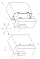
- FIG. 1 It is a figure showing the completed body of the motor control device of an embodiment, and the state in the middle of decomposition by a perspective view. It is a figure showing the state which decomposed
- FIG. 1A is a perspective view of the entire motor control device according to the present embodiment
- FIG. 1B is a perspective view of the motor control device being disassembled.
- the motor control device 100 includes, for example, a controller unit for controlling a motor, a PLC (Programmable Logic Controller) unit, an inverter unit, a servo unit, a power supply unit, an I / O unit, a sensor unit, a switch unit, a safe unit, and a relay unit. And so on.
- a controller unit for controlling a motor for example, a PLC (Programmable Logic Controller) unit, an inverter unit, a servo unit, a power supply unit, an I / O unit, a sensor unit, a switch unit, a safe unit, and a relay unit. And so on.
- a control apparatus What is necessary is just an electronic apparatus by which a printed circuit board is inserted / extracted in a box-shaped housing
- the complete motor control device 100 has a substantially rectangular parallelepiped shape. As shown in FIG. 1B, the entire outline of the motor control device 100 can be disassembled into a front cover portion 2 and a rear housing 1, and a printed circuit board 3 is provided inside the housing 1. Is stored.
- FIG. 2 is a perspective view of the motor control device 100 in a state disassembled in more detail than FIG. 1B in a perspective view from the same direction as FIG.
- the motor control device 100 includes the housing 1, the lid 2, and the printed circuit board 3 as described above.
- the housing 1 is a box having an opening on the front side, and a printed circuit board 3 can be stored therein.
- the lid 2 is a member that can cover the entire front opening 1a of the housing 1, and includes four locking claws 2a on the rear. Note that the number of the locking claws 2a is not limited to four, and may be any other number.
- These locking claws 2a are each provided with a protrusion directed rightward or leftward, and when the lid portion 2 covers the opening 1a of the housing 1, each locking claw 2a is placed inside the housing 1 respectively. Inserted and locked in the corresponding locking holes 1b. Due to the locking of the locking claw 2a and the locking hole 1b, the connection between the lid 2 and the housing 1 is maintained.
- the direction of the protrusion of the locking claw 2a is not limited to the right side or the left side, and may be other directions.
- guide rails 1c are provided on the upper top plate and the lower bottom plate at the same position in the left-right direction.
- Each guide rail 1c is formed with a groove having a width substantially the same as the thickness of the printed circuit board 3, and extends in the front-rear direction.
- the printed circuit board 3 is inserted from the front opening 1a of the housing 1 toward the rear inner side with the upper side and the lower side of the printed board 3 being fitted in the grooves of the guide rail 1c.
- a female connector 4 that is mechanically and electrically attachable / detachable (connectable and separable) to a male connector (object to be connected) of a cable (not shown) for connecting other devices to the front portion of the printed circuit board 3.
- a connection hole 2 b is opened in front of the lid portion 2 in correspondence with the arrangement of the joint portion of the female connector 4.
- the dummy male connector 5 is joined instead of the male connector of the cable. Further, the male and female relationships of the male connector 5 and the female connector 4 may be reversed.
- the female connector 4 of the printed circuit board 3 can be coupled to the external male connector 5 through the connection hole 2b of the lid portion 2.
- the insertion / removal direction of the female connector 4 and the male connector 5 is parallel to the insertion / removal direction of the printed circuit board 3 with respect to the housing 1.
- the insertion / extraction direction here includes both the insertion direction (rear) and the extraction direction (front) of the printed circuit board 3 with respect to the housing 1 and corresponds to the front / rear direction.
- only the housing 1 is set and fixed to a base or the like not particularly shown.
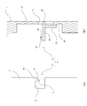
- FIG. 3 shows the configuration of the engagement mechanism.
- FIG. 3A is a side view of the printed circuit board 3 viewed from the right side
- FIG. 3B is a front view of the housing 1 viewed from the front side
- 3 (c) is a side sectional view as seen from the section taken along the line III-c in FIG. 3 (b)
- FIG. 3 (d) is a rear view of the housing 1 as seen from the rear.
- the printed circuit board 3 is provided with an engaged portion 11 at a rear edge portion (side surface on one side in the insertion / extraction direction).
- the rear wall portion 1d of the housing 1 (the wall portion on one side of the housing insertion / removal direction) is substantially at the same left and right position as the guide rail 1c, and the above-mentioned An engaging member 21 is provided at a height position corresponding to the engaged portion 11.
- the engagement mechanism 6 includes the engaged portion 11 of the printed circuit board 3 and the engagement member 21 of the housing 1.
- FIG. 4A shows the engaged portion 11 in an enlarged manner
- FIG. 4B shows the engaging member 21 in an enlarged manner
- the engaged portion 11 of the printed board 3 has a recess 12 and an engaged protrusion 13.
- the recess 12 is formed so as to be cut out in a substantially rectangular shape from the rear edge of the printed circuit board 3 toward the front.
- the engaged protrusion 13 (first protrusion) is a protrusion that protrudes downward from the upper side of the opening position of the recess 12, and an inclined surface 14 (lower left and upper right in the figure) The surface along the surface).
- the engaging member 21 includes a first extending portion 22, a second extending portion 23, a third extending portion 24, a protruding portion 25, and an engaging protruding portion 26.
- the body 1 is integrated with the back wall 1 d of the body 1.
- the first extending portion 22 extends in the front-rear direction and includes an engaging protrusion 26 at an end on the front side.
- the second extending portion 23 extends in the vertical direction, the upper end portion is connected to the first extending portion 22, and the lower end portion is connected via a third extending portion 24 described later.
- the second extending portion 23 itself is connected to the back wall portion 1d of the housing 1 and has flexibility.
- the third extending portion 24 extends in the front-rear direction, the front end portion is connected to the lower end portion of the second extending portion 23, and the rear end portion is the rear surface of the housing 1. It is connected to the wall 1d. Further, the second extending portion 23 is connected to the rear wall portion 1d via the third extending portion 24, so that the second extending portion 23 is located on the inner side (for example, the front side) from the rear wall portion 1d, and the upper end portion. Is connected to an end portion on the rear side of the first extending portion 22 (in other words, an intermediate position between the first extending portion 22 and a protruding portion 25 described later).
- first extending portion 22 protrudes toward the rear side from the connecting position with the second extending portion 23 at the rear end portion, and the tip thereof substantially corresponds to the outer peripheral surface of the back wall portion 1d. It has the protrusion part 25 used as the surface.
- the engaging protrusion 26 is a protrusion protruding upward at the front end of the first extending portion 22, and an inclined surface 27 (in the drawing) A surface along the lower left and upper right).
- an operation hole 1e is provided in the rear wall 1d of the housing 1 so that an operator can easily contact the protruding portion 25 with his / her finger or the like.
- the to-be-engaged portion 11 on the printed circuit board 3 side and the engaging member 21 on the housing 1 side have an arrangement relationship in which the inclined surfaces 14 and 27 are substantially at the same position in the vertical direction (direction perpendicular to the insertion / extraction direction). Each is installed to be.
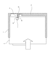
- FIG. 5 is a diagram showing a state of the engagement mechanism 6 during insertion when the printed circuit board 3 is stored, and is a side view of the printed circuit board 3 in FIG. 3A and a side cross section in FIG. 3C. It shows corresponding to the figure.
- the inclined surfaces 14 and 27 slip and the component force that pushes down on the engaging projection 26 acts.
- the second extending portion 23 of the engaging member 21 is bent, and the engaging protrusion 26 swings downward.
- the printed circuit board 3 can be further inserted into the housing 1, and finally the engagement protrusion 26 is returned to the original height position as shown in FIG. The engagement protrusion 26 is engaged.
- the printed circuit board 3 cannot contact the inner surface of the back wall 1d of the housing 1 except for the periphery of the engagement mechanism 6 in the rear edge of the printed circuit board 3, and the printed circuit board 3 cannot be inserted any more. That is, in this state, the movement of the printed circuit board 3 with respect to the housing 1 is restricted in both the forward and backward directions by the engagement by the engagement mechanism 6 and the contact with the rear wall 1d. That is, the printed circuit board 3 and the housing 1 are firmly connected inside the housing 1. Thus, even when the male connector 5 coupled to the female connector 4 of the printed circuit board 3 is pulled away, the cover portion 2 and the printed circuit board 3 are prevented from being pulled out from the housing 1 as shown in FIG.
- connection state of the housing 1, the printed circuit board 3, and the lid 2 can be maintained.
- the engagement mechanism 6 is prevented from being subjected to a vertical or rotational component force by offsetting the installation position of the female connector 4 and the installation position of the engagement mechanism 6 in the vertical direction. 6 may be installed at a close position corresponding to the female connector 4 of the printed circuit board 3 in the vertical direction.
- the engagement member 21 can be removed with an operator's finger (not shown) through the operation hole 1e.
- the protrusion 25 is operated to be pushed into the housing 1 (for example, the front side) slightly upward. Thereby, the 2nd extension part 23 of the engagement member 21 bends, and the engagement protrusion part 26 moves below. In this way, the printed circuit board 3 can be easily detached from the housing 1 by releasing the engagement between the engaging protrusion 26 and the engaged protrusion 13.
- the concave portion 12 of the printed circuit board 3 allows the downward movement of the engaging protrusion 26 so that the engaging protrusion 26 can move downward and be sufficiently separated from the engaged protrusion 13 in this way. 15 (see FIG. 4A).
- the rear side corresponds to one side of the insertion / extraction direction described in each claim
- the front side corresponds to the other side of the insertion / extraction direction described in each claim
- the lower side is a direction inclined with respect to the insertion / extraction direction described in each claim. It corresponds to a direction perpendicular to the insertion / extraction direction
- the upper side corresponds to a direction inclined with respect to the insertion / extraction direction described in each claim.
- the motor control device 100 includes the engaged portion 11 on the rear side surface of the printed circuit board 3, and when the printed circuit board 3 is inserted into the housing 1,
- the engaging member 21 provided on the rear wall portion 1 d on the side engages with the engaged portion 11 of the printed circuit board 3.
- the movement of the printed circuit board 3 in the insertion / extraction direction is restricted.
- the engagement of the engagement member 21 and the engaged portion 11 in the engagement mechanism 6 restricts the movement of the printed circuit board 3 in the direction opposite to the insertion direction (forward), and the back surface of the printed circuit board 3.
- the movement of the printed circuit board 3 in the insertion direction (backward) is restricted by the contact with the wall 1d.
- the printed circuit board 3 can be firmly fixed to the housing 1.
- the engagement member 21 is configured to be disengaged by being pressed from the outside of the housing 1 toward the front side.
- the engaging member 21 is located on the back wall 1d opposite to the opening 1a of the housing 1, the operator presses the engaging member 21 while holding the housing 1 with one hand.
- the printed circuit board 3 can be easily detached from the housing 1.
- the engaged portion 11 of the printed circuit board 3 has an engaged protrusion 13 and a recessed portion 12 protruding downward, and the engaging member 21 of the housing 1 protrudes upward.
- a protrusion 26 is provided.
- the engaged protrusions 13 and the engaging protrusions 26 that protrude so as to face each other in a direction perpendicular to the insertion / extraction direction of the printed circuit board 3 are engaged with each other. Therefore, the printed circuit board 3 can be firmly fixed by the housing 1.
- the engagement protrusion 26 is configured to move in the vertical direction perpendicular to the insertion / extraction direction, so that the engagement between the engagement protrusion 13 and the engagement protrusion 26 and the release thereof can be switched more reliably. It becomes possible.
- the engaged protrusion 13 in the rear side
- the engagement protrusion 26 of the engagement member 21 (The front side) is brought into contact, and by this contact, the engaging protrusion 26 is pressed and moved downward, and the engaged protrusion 13 and the engaging protrusion 26 are engaged.
- the inclined projections 14 and 27 are provided on the rear side of the engaged projection 13 and the front side of the engagement projection 26, respectively, so that when both the projections 13 and 26 come into contact, the engagement projection 26 can be moved smoothly. Therefore, the engaged protrusion 13 and the engagement protrusion 26 can be smoothly engaged.
- the male connector 5 is inserted into and removed from the female connector 4 mounted on the printed circuit board 3 in the insertion / removal direction (front-rear direction) of the printed circuit board 3.
- a pulling force acts on the printed circuit board 3 in a direction (front direction) opposite to the insertion direction (rear direction) of the printed circuit board 3.
- the printed circuit board 3 may come off from the housing 1.
- this embodiment is particularly effective in the case of the printed circuit board 3 on which such a female connector 4 is mounted.
- the recess 12 having the engaged protrusion 13 is formed on the side surface of the printed circuit board 3 so that the vertical position perpendicular to the insertion / extraction direction of the printed circuit board 3 corresponds to the female connector 4.
- the engaged portion 11 and the engaging member 21 can be engaged with each other on the opposite side of the position where the pulling force acts on the printed circuit board 3, so that the printed circuit board 3 can be fixed stably and more firmly. can do.
- the engaging member 21 includes a first extending portion 22 extending in the insertion / extraction direction (front-rear direction) and a second extending portion extending in the vertical direction perpendicular to the insertion / extraction direction. 23. Since the second extending portion 23 is flexible, the first extending portion 22 connected to the second extending portion 23 swings at a right angle, and the engaging protrusion 26 provided at the end of the first extending portion 22 is connected to the printed board 3. It can be configured to move in the vertical direction perpendicular to the insertion / extraction direction. Therefore, it is possible to realize a structure in which the engaged protrusion 13 provided on the printed circuit board 3 and the engaging protrusion 26 of the engaging member 21 are engaged and released.
- the engaging member 21 has the third extending portion 24, whereby the second extending portion 23 is disposed on the inner side of the back wall portion 1 d, and the first extending portion 22 is the first extending portion 22. 2 It has the protrusion part 25 which protrudes toward the insertion / extraction direction one side from a connection position with the extension part 23. As shown in FIG.
- the protrusion 25 makes it easy for the operator to push the engaging member 21 forward from the outside of the housing 1, and operability can be improved.
- the tip of the protruding portion 25 is substantially flush with the outer peripheral surface of the back wall portion 1d, the protruding portion 25 does not protrude from the housing 1. Thereby, the installation space can be reduced, and the protrusion 25 does not get in the way when the housing 1 is attached, placed, or arranged. Moreover, it is also possible to place it flat with the back wall 1d side facing downward.
- tip of the protrusion part 25 does not necessarily need to be flush with the outer peripheral surface of the back wall part 1d, and may protrude from the outer peripheral surface of the back wall part 1d. In this case, it becomes easier for the operator to push the protruding portion 25 toward the front side, and the operability can be further improved.
- the arrangement relationship of the entire engagement mechanism 6 may be completely reversed upside down. In this case, what is necessary is just to operate so that the protrusion part 25 may be pushed down when releasing engagement.
- the engaged portion 11 on the printed circuit board 3 side has a convex portion 16 as shown in FIG. 8 instead of the concave portion 12 and is provided with an engaged projection portion 13 at the rear end portion thereof. Also good.
- the engaging member 21 may have a simple structure as shown in FIG. That is, the rear side surface of the second extending portion 23 may be provided so as to be substantially flush with the outer peripheral surface of the back wall portion 1d without providing the third extending portion 24 and the protruding portion 25.
- FIG. 9C is a rear view corresponding to FIG. Even with such a configuration, the engagement mechanism 6 can be engaged by inserting the printed circuit board 3 and the engagement mechanism 6 can be released by pushing the second extending portion 23.
- the engagement member 21 may be configured to release the engagement of the engagement mechanism 6 by pulling the protruding portion 25.
- the protrusion direction (downward direction) of the engaged protrusion 13 from the first extension portion 22 is set to the second extension portion 22 in the first extension portion 22. What is necessary is just to make it the same direction as the connection direction (downward direction shown in figure) of the part 23.
- FIG. Accordingly, the protruding direction (upward direction in the drawing) of the engaged protrusion 13 in the engaged portion 11 is also made to correspond.
- the movement of the printed circuit board 3 to the rear is restricted by contact with the back wall portion 1d of the printed circuit board 3, and the front of the printed circuit board 3 by the engagement of the engagement mechanism 6 (although movement to the other side in the insertion / removal direction is regulated, the present invention is not limited to this. That is, the movement of the printed circuit board 3 in the front-rear direction (insertion / removal direction) may be regulated by the engagement of the engagement mechanism 6. Although illustration is omitted, in this case, for example, when the engagement mechanism 6 is engaged with the engagement protrusion 13, the front end of the first extension 22 is the front of the recess 12.
Landscapes
- Engineering & Computer Science (AREA)
- Microelectronics & Electronic Packaging (AREA)
- Mounting Of Printed Circuit Boards And The Like (AREA)
- Motor Or Generator Frames (AREA)
- Casings For Electric Apparatus (AREA)
Abstract
Priority Applications (5)
| Application Number | Priority Date | Filing Date | Title |
|---|---|---|---|
| EP13886608.2A EP3007529A1 (fr) | 2013-06-04 | 2013-06-04 | Dispositif de commande de moteur |
| JP2015521197A JP6143026B2 (ja) | 2013-06-04 | 2013-06-04 | モータ制御装置 |
| PCT/JP2013/065441 WO2014196016A1 (fr) | 2013-06-04 | 2013-06-04 | Dispositif de commande de moteur |
| CN201380077178.XA CN105309059B (zh) | 2013-06-04 | 2013-06-04 | 电机控制装置 |
| US14/955,041 US20160095233A1 (en) | 2013-06-04 | 2015-12-01 | Motor control device and electronic equipment |
Applications Claiming Priority (1)
| Application Number | Priority Date | Filing Date | Title |
|---|---|---|---|
| PCT/JP2013/065441 WO2014196016A1 (fr) | 2013-06-04 | 2013-06-04 | Dispositif de commande de moteur |
Related Child Applications (1)
| Application Number | Title | Priority Date | Filing Date |
|---|---|---|---|
| US14/955,041 Continuation US20160095233A1 (en) | 2013-06-04 | 2015-12-01 | Motor control device and electronic equipment |
Publications (1)
| Publication Number | Publication Date |
|---|---|
| WO2014196016A1 true WO2014196016A1 (fr) | 2014-12-11 |
Family
ID=52007692
Family Applications (1)
| Application Number | Title | Priority Date | Filing Date |
|---|---|---|---|
| PCT/JP2013/065441 Ceased WO2014196016A1 (fr) | 2013-06-04 | 2013-06-04 | Dispositif de commande de moteur |
Country Status (5)
| Country | Link |
|---|---|
| US (1) | US20160095233A1 (fr) |
| EP (1) | EP3007529A1 (fr) |
| JP (1) | JP6143026B2 (fr) |
| CN (1) | CN105309059B (fr) |
| WO (1) | WO2014196016A1 (fr) |
Cited By (1)
| Publication number | Priority date | Publication date | Assignee | Title |
|---|---|---|---|---|
| JP2022131173A (ja) * | 2021-02-26 | 2022-09-07 | 株式会社安川電機 | 制御装置 |
Families Citing this family (8)
| Publication number | Priority date | Publication date | Assignee | Title |
|---|---|---|---|---|
| JP6275683B2 (ja) * | 2015-12-02 | 2018-02-07 | 矢崎総業株式会社 | 基板保持構造、電子部品モジュール、および電気接続箱 |
| CN109845420B (zh) * | 2016-10-24 | 2021-06-01 | 三菱电机株式会社 | 车载用电子设备 |
| US9967993B1 (en) | 2016-11-07 | 2018-05-08 | Phoenix Contact Development and Manufacturing, Inc. | Printed circuit board enclosure assembly |
| KR20190048558A (ko) * | 2017-10-31 | 2019-05-09 | 삼성전자주식회사 | 디스플레이 장치 |
| JP6599967B2 (ja) * | 2017-12-25 | 2019-10-30 | ファナック株式会社 | 電子装置 |
| US11419228B2 (en) * | 2018-04-03 | 2022-08-16 | Microsoft Technology Licensing, Llc | Locking mechanisms in separable and repairable devices |
| JP7015259B2 (ja) * | 2019-02-07 | 2022-02-02 | ファナック株式会社 | スナップフィット |
| TWI714429B (zh) * | 2020-01-10 | 2020-12-21 | 群光電能科技股份有限公司 | 電源轉換器 |
Citations (4)
| Publication number | Priority date | Publication date | Assignee | Title |
|---|---|---|---|---|
| JPS6196588U (fr) * | 1984-11-28 | 1986-06-21 | ||
| JPS61186282U (fr) * | 1985-05-11 | 1986-11-20 | ||
| JPH0327084U (fr) * | 1989-07-26 | 1991-03-19 | ||
| JP2001111264A (ja) | 1999-10-13 | 2001-04-20 | Fuji Electric Co Ltd | 情報処理装置 |
Family Cites Families (12)
| Publication number | Priority date | Publication date | Assignee | Title |
|---|---|---|---|---|
| JPH0511489U (ja) * | 1991-07-22 | 1993-02-12 | シヤープ株式会社 | 部品の取付装置 |
| US5973926A (en) * | 1996-02-29 | 1999-10-26 | Palo Alto Design Group, Inc. | Method and apparatus for attaching circuit board to chassis and forming solid ground connection using a single screw |
| US6033234A (en) * | 1998-02-19 | 2000-03-07 | Packard Hughes Interconnect Company | Printed circuit board to flexible printed circuit connection system |
| DE19911990A1 (de) * | 1999-03-17 | 2000-09-28 | Trw Automotive Electron & Comp | Metallgehäuse, insbesondere für ein Airbag-Steuergerät |
| JP2001196770A (ja) * | 2000-01-12 | 2001-07-19 | Omron Corp | コントロールユニット |
| JP2001237557A (ja) * | 2000-02-24 | 2001-08-31 | Keihin Corp | 電子回路基板の収容ケース |
| JP3726628B2 (ja) * | 2000-03-17 | 2005-12-14 | 松下電器産業株式会社 | モータ制御装置 |
| JP3902445B2 (ja) * | 2001-11-06 | 2007-04-04 | 株式会社山武 | 電子機器筐体の取付装置 |
| US7265988B2 (en) * | 2004-03-22 | 2007-09-04 | Hewlett-Packard Development Company, L.P. | Circuit board module including an integral connector panel |
| CN102780132A (zh) * | 2011-05-13 | 2012-11-14 | 鸿富锦精密工业(深圳)有限公司 | 板卡固定装置 |
| TW201304658A (zh) * | 2011-07-08 | 2013-01-16 | Hon Hai Prec Ind Co Ltd | 主機板安裝裝置 |
| CN102761022B (zh) * | 2012-06-27 | 2015-03-18 | 华为技术有限公司 | 一种用于插拔pcb板的连杆装置 |
-
2013
- 2013-06-04 EP EP13886608.2A patent/EP3007529A1/fr not_active Withdrawn
- 2013-06-04 JP JP2015521197A patent/JP6143026B2/ja active Active
- 2013-06-04 CN CN201380077178.XA patent/CN105309059B/zh active Active
- 2013-06-04 WO PCT/JP2013/065441 patent/WO2014196016A1/fr not_active Ceased
-
2015
- 2015-12-01 US US14/955,041 patent/US20160095233A1/en not_active Abandoned
Patent Citations (4)
| Publication number | Priority date | Publication date | Assignee | Title |
|---|---|---|---|---|
| JPS6196588U (fr) * | 1984-11-28 | 1986-06-21 | ||
| JPS61186282U (fr) * | 1985-05-11 | 1986-11-20 | ||
| JPH0327084U (fr) * | 1989-07-26 | 1991-03-19 | ||
| JP2001111264A (ja) | 1999-10-13 | 2001-04-20 | Fuji Electric Co Ltd | 情報処理装置 |
Cited By (2)
| Publication number | Priority date | Publication date | Assignee | Title |
|---|---|---|---|---|
| JP2022131173A (ja) * | 2021-02-26 | 2022-09-07 | 株式会社安川電機 | 制御装置 |
| JP7196942B2 (ja) | 2021-02-26 | 2022-12-27 | 株式会社安川電機 | 制御装置 |
Also Published As
| Publication number | Publication date |
|---|---|
| CN105309059B (zh) | 2018-09-28 |
| EP3007529A1 (fr) | 2016-04-13 |
| JPWO2014196016A1 (ja) | 2017-02-23 |
| JP6143026B2 (ja) | 2017-06-07 |
| US20160095233A1 (en) | 2016-03-31 |
| CN105309059A (zh) | 2016-02-03 |
Similar Documents
| Publication | Publication Date | Title |
|---|---|---|
| JP6143026B2 (ja) | モータ制御装置 | |
| US10492324B2 (en) | Electronic device | |
| JP6458745B2 (ja) | 装置ユニット | |
| JP4832183B2 (ja) | モジュラープラグ | |
| US10455721B2 (en) | Electronic device | |
| JP2005237196A (ja) | ジャンクションボックス及びその組立方法 | |
| JP5782472B2 (ja) | 電子機器 | |
| JP2008090148A (ja) | 光トランシーバモジュール | |
| JP5444401B2 (ja) | 筐体の取付け構造 | |
| JP2014179499A (ja) | 電気機器 | |
| JP2012190706A (ja) | コネクタ装置 | |
| JP5262298B2 (ja) | 電源装置 | |
| JP4785632B2 (ja) | 電子機器における機器ユニットの着脱構造 | |
| JP2007299803A (ja) | 電気機器の外郭構造 | |
| JP6570318B2 (ja) | 基板ユニットのロック構造 | |
| JP6434453B2 (ja) | 本体ケース、端子装置、スイッチ装置および制御装置 | |
| JP5828331B2 (ja) | コネクタ | |
| JP2022160913A (ja) | 通信機器の設置構造 | |
| JP2005102353A (ja) | ハーネスクランプ、および画像形成装置 | |
| JP2006260829A (ja) | 端子台の端子カバー装置 | |
| JP4543255B2 (ja) | 電気機器キャビネット | |
| JP3690302B2 (ja) | 配線器具用プレート | |
| JP4543975B2 (ja) | 電子制御機器の連結構造 | |
| JP2019175683A (ja) | リレーソケットおよびそれを備えたリレーボックス | |
| JP5131019B2 (ja) | 着脱自在な操作部を備えた電気機器 |
Legal Events
| Date | Code | Title | Description |
|---|---|---|---|
| WWE | Wipo information: entry into national phase |
Ref document number: 201380077178.X Country of ref document: CN |
|
| 121 | Ep: the epo has been informed by wipo that ep was designated in this application |
Ref document number: 13886608 Country of ref document: EP Kind code of ref document: A1 |
|
| ENP | Entry into the national phase |
Ref document number: 2015521197 Country of ref document: JP Kind code of ref document: A |
|
| NENP | Non-entry into the national phase |
Ref country code: DE |
|
| WWE | Wipo information: entry into national phase |
Ref document number: 2013886608 Country of ref document: EP |