WO2014196237A1 - Dispositif de contrôle de distribution variable pour moteur à combustion interne, et procédé de contrôle - Google Patents
Dispositif de contrôle de distribution variable pour moteur à combustion interne, et procédé de contrôle Download PDFInfo
- Publication number
- WO2014196237A1 WO2014196237A1 PCT/JP2014/055933 JP2014055933W WO2014196237A1 WO 2014196237 A1 WO2014196237 A1 WO 2014196237A1 JP 2014055933 W JP2014055933 W JP 2014055933W WO 2014196237 A1 WO2014196237 A1 WO 2014196237A1
- Authority
- WO
- WIPO (PCT)
- Prior art keywords
- valve timing
- operation amount
- variable valve
- internal combustion
- combustion engine
- Prior art date
- Legal status (The legal status is an assumption and is not a legal conclusion. Google has not performed a legal analysis and makes no representation as to the accuracy of the status listed.)
- Ceased
Links
Images









Classifications
-
- F—MECHANICAL ENGINEERING; LIGHTING; HEATING; WEAPONS; BLASTING
- F02—COMBUSTION ENGINES; HOT-GAS OR COMBUSTION-PRODUCT ENGINE PLANTS
- F02D—CONTROLLING COMBUSTION ENGINES
- F02D13/00—Controlling the engine output power by varying inlet or exhaust valve operating characteristics, e.g. timing
- F02D13/02—Controlling the engine output power by varying inlet or exhaust valve operating characteristics, e.g. timing during engine operation
-
- F—MECHANICAL ENGINEERING; LIGHTING; HEATING; WEAPONS; BLASTING
- F02—COMBUSTION ENGINES; HOT-GAS OR COMBUSTION-PRODUCT ENGINE PLANTS
- F02D—CONTROLLING COMBUSTION ENGINES
- F02D13/00—Controlling the engine output power by varying inlet or exhaust valve operating characteristics, e.g. timing
- F02D13/02—Controlling the engine output power by varying inlet or exhaust valve operating characteristics, e.g. timing during engine operation
- F02D13/0203—Variable control of intake and exhaust valves
-
- F—MECHANICAL ENGINEERING; LIGHTING; HEATING; WEAPONS; BLASTING
- F02—COMBUSTION ENGINES; HOT-GAS OR COMBUSTION-PRODUCT ENGINE PLANTS
- F02D—CONTROLLING COMBUSTION ENGINES
- F02D13/00—Controlling the engine output power by varying inlet or exhaust valve operating characteristics, e.g. timing
- F02D13/02—Controlling the engine output power by varying inlet or exhaust valve operating characteristics, e.g. timing during engine operation
- F02D13/0203—Variable control of intake and exhaust valves
- F02D13/0215—Variable control of intake and exhaust valves changing the valve timing only
-
- F—MECHANICAL ENGINEERING; LIGHTING; HEATING; WEAPONS; BLASTING
- F02—COMBUSTION ENGINES; HOT-GAS OR COMBUSTION-PRODUCT ENGINE PLANTS
- F02D—CONTROLLING COMBUSTION ENGINES
- F02D13/00—Controlling the engine output power by varying inlet or exhaust valve operating characteristics, e.g. timing
- F02D13/02—Controlling the engine output power by varying inlet or exhaust valve operating characteristics, e.g. timing during engine operation
- F02D13/0223—Variable control of the intake valves only
- F02D13/0234—Variable control of the intake valves only changing the valve timing only
-
- F—MECHANICAL ENGINEERING; LIGHTING; HEATING; WEAPONS; BLASTING
- F02—COMBUSTION ENGINES; HOT-GAS OR COMBUSTION-PRODUCT ENGINE PLANTS
- F02D—CONTROLLING COMBUSTION ENGINES
- F02D13/00—Controlling the engine output power by varying inlet or exhaust valve operating characteristics, e.g. timing
- F02D13/02—Controlling the engine output power by varying inlet or exhaust valve operating characteristics, e.g. timing during engine operation
- F02D13/0242—Variable control of the exhaust valves only
- F02D13/0249—Variable control of the exhaust valves only changing the valve timing only
-
- F—MECHANICAL ENGINEERING; LIGHTING; HEATING; WEAPONS; BLASTING
- F02—COMBUSTION ENGINES; HOT-GAS OR COMBUSTION-PRODUCT ENGINE PLANTS
- F02D—CONTROLLING COMBUSTION ENGINES
- F02D41/00—Electrical control of supply of combustible mixture or its constituents
- F02D41/02—Circuit arrangements for generating control signals
- F02D41/14—Introducing closed-loop corrections
- F02D41/1401—Introducing closed-loop corrections characterised by the control or regulation method
-
- F—MECHANICAL ENGINEERING; LIGHTING; HEATING; WEAPONS; BLASTING
- F01—MACHINES OR ENGINES IN GENERAL; ENGINE PLANTS IN GENERAL; STEAM ENGINES
- F01L—CYCLICALLY OPERATING VALVES FOR MACHINES OR ENGINES
- F01L1/00—Valve-gear or valve arrangements, e.g. lift-valve gear
- F01L1/34—Valve-gear or valve arrangements, e.g. lift-valve gear characterised by the provision of means for changing the timing of the valves without changing the duration of opening and without affecting the magnitude of the valve lift
-
- F—MECHANICAL ENGINEERING; LIGHTING; HEATING; WEAPONS; BLASTING
- F01—MACHINES OR ENGINES IN GENERAL; ENGINE PLANTS IN GENERAL; STEAM ENGINES
- F01L—CYCLICALLY OPERATING VALVES FOR MACHINES OR ENGINES
- F01L2800/00—Methods of operation using a variable valve timing mechanism
-
- F—MECHANICAL ENGINEERING; LIGHTING; HEATING; WEAPONS; BLASTING
- F02—COMBUSTION ENGINES; HOT-GAS OR COMBUSTION-PRODUCT ENGINE PLANTS
- F02D—CONTROLLING COMBUSTION ENGINES
- F02D41/00—Electrical control of supply of combustible mixture or its constituents
- F02D41/0002—Controlling intake air
- F02D2041/001—Controlling intake air for engines with variable valve actuation
-
- F—MECHANICAL ENGINEERING; LIGHTING; HEATING; WEAPONS; BLASTING
- F02—COMBUSTION ENGINES; HOT-GAS OR COMBUSTION-PRODUCT ENGINE PLANTS
- F02D—CONTROLLING COMBUSTION ENGINES
- F02D41/00—Electrical control of supply of combustible mixture or its constituents
- F02D41/02—Circuit arrangements for generating control signals
- F02D41/14—Introducing closed-loop corrections
- F02D41/1401—Introducing closed-loop corrections characterised by the control or regulation method
- F02D2041/1409—Introducing closed-loop corrections characterised by the control or regulation method using at least a proportional, integral or derivative controller
-
- F—MECHANICAL ENGINEERING; LIGHTING; HEATING; WEAPONS; BLASTING
- F02—COMBUSTION ENGINES; HOT-GAS OR COMBUSTION-PRODUCT ENGINE PLANTS
- F02D—CONTROLLING COMBUSTION ENGINES
- F02D2200/00—Input parameters for engine control
- F02D2200/50—Input parameters for engine control said parameters being related to the vehicle or its components
- F02D2200/503—Battery correction, i.e. corrections as a function of the state of the battery, its output or its type
-
- F—MECHANICAL ENGINEERING; LIGHTING; HEATING; WEAPONS; BLASTING
- F02—COMBUSTION ENGINES; HOT-GAS OR COMBUSTION-PRODUCT ENGINE PLANTS
- F02D—CONTROLLING COMBUSTION ENGINES
- F02D2200/00—Input parameters for engine control
- F02D2200/70—Input parameters for engine control said parameters being related to the vehicle exterior
-
- Y—GENERAL TAGGING OF NEW TECHNOLOGICAL DEVELOPMENTS; GENERAL TAGGING OF CROSS-SECTIONAL TECHNOLOGIES SPANNING OVER SEVERAL SECTIONS OF THE IPC; TECHNICAL SUBJECTS COVERED BY FORMER USPC CROSS-REFERENCE ART COLLECTIONS [XRACs] AND DIGESTS
- Y02—TECHNOLOGIES OR APPLICATIONS FOR MITIGATION OR ADAPTATION AGAINST CLIMATE CHANGE
- Y02T—CLIMATE CHANGE MITIGATION TECHNOLOGIES RELATED TO TRANSPORTATION
- Y02T10/00—Road transport of goods or passengers
- Y02T10/10—Internal combustion engine [ICE] based vehicles
- Y02T10/12—Improving ICE efficiencies
Definitions
- the present invention relates to a variable valve timing control device and a control method for changing the valve timing of an internal combustion engine.
- Patent Document 1 a sensor for measuring the position of a variable valve timing mechanism (VTC) is provided as in Patent Document 1, for example.
- VTC variable valve timing mechanism
- a technique for controlling the target position based on the measurement result is known.
- a motor rotation speed sensor is provided in a motor for varying the turning speed of the planetary gear in the phase variable mechanism, and the VTC position is detected by the rotation signal of the motor shaft that is detected more frequently than the rotation signal of the cam shaft. is doing.
- the motor rotation speed sensor it is possible to detect the VTC position even during a period in which the rotation signal of the camshaft cannot be detected, and to realize accurate valve timing control in the low rotation region of the engine. ing. Since the VTC position detection system by adding such a sensor does not depend on the engine speed, controllability can be ensured even when the engine is running at a low speed.
- an additional sensor for detecting the VTC position may be omitted depending on a customer request or an inexpensive system request.
- the valve timing is controlled using a crank angle sensor or the like. Then, the target valve timing is calculated according to the operating state of the engine, the actual valve timing is detected at the position measurement timing by the crank angle sensor, and the differential operation amount according to the deviation between the target valve timing and the actual valve timing is used. Feedback control is performed to converge to the target value (target valve timing).
- crank angle sensor since the crank angle sensor has a low frequency of position measurement, control using a large differential operation amount is necessary to ensure controllability at the time of engine start (during cranking) or at a low engine speed. For this reason, it has been a challenge to deal with the effects of an increase in effective current and current variation.
- the convergence control such as PID control requires a large differential operation amount (brake) in order to converge to the target value without overshoot.
- This large differential operation amount increases the effective current, and there is no design margin for the motor heat resistance, or the power consumption increases and the fuel efficiency effect is lost. Further, if the amount of current change is large, there is a possibility that the demagnetization of the motor magnet may occur.
- the present invention has been made in view of the above circumstances, and its purpose is to increase the effective current and the amount of current change while maintaining the brake function without adding a sensor for detecting the VTC position. It is an object to provide a variable valve timing control device and control method for an internal combustion engine that can suppress the above-described problem.
- variable valve timing control device and control method for an internal combustion engine calculates an operation amount for controlling the valve timing, and calculates the operation amount calculated at the position detection timing of the variable valve timing mechanism until the next position detection timing. Divide between and output.
- the operation amount calculated at the position detection timing of the variable valve timing mechanism is not given all at once, but is divided and output until the next position detection timing.
- the peak value of the operation amount can be lowered, the effective current can be reduced, and the current change amount can be reduced, and the countermeasure to the accompanying phenomenon can be reduced or eliminated. Therefore, according to the present invention, it is possible to suppress an increase in effective current and current change amount while maintaining a brake function without adding a sensor for detecting a VTC position.
- FIG. 1 is a schematic diagram showing a system configuration of a vehicle engine to which a variable valve timing control device for an internal combustion engine according to an embodiment of the present invention is applied. It is a flowchart which shows the procedure which calculates the brake operation amount in the variable valve timing control apparatus of the internal combustion engine which concerns on the 1st Embodiment of this invention.
- 3 is a timing chart of each signal in the flowchart shown in FIG. 2.
- FIG. 4 is a waveform diagram of a cam phase angle, a control voltage, a motor current, and a differential operation amount in the present invention. It is a waveform diagram of the cam phase angle, control voltage, motor current, and differential operation amount of a comparative example.
- FIG. 10 is a timing chart of each signal in the flowcharts shown in FIGS. 8 and 9.
- FIG. 10 is a timing chart of each signal in the flowcharts shown in FIGS. 8 and 9.
- FIG. 10 is a waveform diagram of a cam phase angle, a control voltage, a motor current, and a differential operation amount when the engine is rotating at a low speed in FIGS. 8 and 9. It is a flowchart which shows a part of procedure which calculates the brake operation amount in the variable valve timing control apparatus of the internal combustion engine which concerns on the 4th Embodiment of this invention. It is a flowchart which shows the procedure following FIG. 14 is a timing chart of each signal in the flowcharts shown in FIGS. 12 and 13. It is a flowchart which shows a part of procedure which calculates the brake operation amount in the variable valve timing control apparatus of the internal combustion engine which concerns on the 5th Embodiment of this invention. It is a flowchart which shows the procedure following FIG.
- FIG. 1 is a schematic diagram showing a system configuration of a vehicle engine to which a variable valve timing control device for an internal combustion engine according to an embodiment of the present invention is applied, and relates to control of an electric actuator used in a variable valve timing mechanism. The part is extracted and shown.
- crankshaft 2 of the engine (internal combustion engine) 1 Power from the crankshaft 2 of the engine (internal combustion engine) 1 is transmitted to the intake side camshaft 4 and the exhaust side camshaft 5 via a timing chain (or timing belt) 3.
- the intake valve is driven to open as the intake side camshaft 4 rotates, and the exhaust valve is driven to open as the exhaust side camshaft 5 rotates.
- the intake camshaft 4 is provided with a variable valve timing mechanism (VTC) 6 that changes the central phase of the intake valve operating angle by changing the rotational phase of the intake camshaft 4 with respect to the crankshaft 2. .
- VTC 6 changes the central phase of the valve operating angle of the intake valve forward and backward without changing the valve operating angle and valve lift amount of the intake valve.
- the VTC 6 is provided on the intake camshaft 4 side, but may be provided on the exhaust camshaft 5 side.
- crankshaft 2 is supported by a signal plate 8 provided with a detected portion (for example, a protruding portion) 7 and a crank angle sensor 9 for detecting the detected portion 7.
- the intake side camshaft 4 is pivotally supported by a signal plate 11 on which a detected portion (for example, a protruding portion) 10 is provided, and is provided with a cam angle sensor 12 for detecting the detected portion 10.
- the detection signal Ne of the crank angle sensor 9 and the detection signal Nc of the cam angle sensor 12 are respectively input to an engine control unit (ECU) 13 that controls the engine 1.
- the ECU 13 receives detection signals (intake air) from an air flow meter 14 that detects the amount of intake air of the engine 1, a temperature sensor 15 that measures environmental temperature, a voltmeter 16 that measures a power supply voltage for driving the motor of the electric VTC, and the like. Quantity Qa, environmental temperature T, and drive power supply voltage VMOT) are input.
- the ECU 13 performs various controls on the engine 1 by executing a control program stored in a storage device such as a read only memory (ROM) or a flash memory based on detection signals from the various sensors. Then, the ECU 13 calculates the engine speed RPM based on the detection signal Ne from the crank angle sensor 9, and performs fuel injection based on the calculated engine speed RPM, the intake air amount Qa detected by the air flow meter 14, and the like. In addition to performing control and ignition control, the control signal CS is supplied to the VTC 6 to control the valve timing.
- a control program stored in a storage device such as a read only memory (ROM) or a flash memory based on detection signals from the various sensors. Then, the ECU 13 calculates the engine speed RPM based on the detection signal Ne from the crank angle sensor 9, and performs fuel injection based on the calculated engine speed RPM, the intake air amount Qa detected by the air flow meter 14, and the like.
- the control signal CS is supplied to the VTC 6 to control the valve timing.
- convergence control such as PID control is used.
- the target valve timing (target advance amount) is calculated based on the engine speed RPM, the intake air amount Qa, and the like, and the crank angle sensor 9 and the cam angle are also calculated.
- the actual valve timing (actual advance angle amount) is detected, and according to the deviation between the target valve timing and the actual valve timing, the operation amount of the VTC 6, for example, the brake operation amount ( In the case of PID control, the differential operation amount) is calculated and feedback controlled.
- ECU13 works as a control unit which has a function as a control device of VTC6. Further, in the control of the VTC 6, the crank angle sensor 9 and the cam angle sensor 12 function as a measurement unit that periodically measures the valve timing.
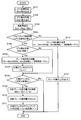
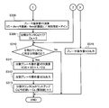
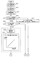
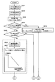
- FIG. 2 is a flowchart showing a procedure for calculating a brake operation amount in the variable valve timing control apparatus for an internal combustion engine according to the first embodiment of the present invention.
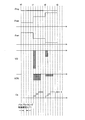
- FIG. 3 is a timing chart of each signal in the flowchart shown in FIG.
- step S101 the target angle ⁇ trg calculated by the ECU 13 based on the engine speed RPM, the intake air amount Qa, and the like is read.
- the target angle ⁇ trg is a predetermined value as shown in FIG.
- step S102 the detection angle ⁇ det based on the detection signal Nc from the cam angle sensor 12 is read.
- the detected angle ⁇ det is a constant value from each VTC position detection timing t0, t1, t2,... To the next timing, and rises stepwise toward the target angle ⁇ trg.
- This deviation amount ⁇ err decreases stepwise as the difference between the detected angle ⁇ det and the target angle ⁇ trg gradually decreases.
- step S104 it is determined whether or not the valve timing control period ⁇ T1 is smaller than the VTC angle detection period. This is because the load on the ECU 13 due to the calculation is reduced by applying the present invention only when the engine 1 is running at a low speed. If the valve timing control period ⁇ T1 is smaller than the VTC angle detection period, the process proceeds to step S105 to determine whether or not the VTC detection angle ⁇ det has been updated.
- a brake operation amount VD for example, a differential operation amount is calculated.
- the brake operation amount VD is expressed by the following equation (1).
- VD ( ⁇ err (current value) ⁇ err (previous value)) / control cycle ⁇ gain (1)
- the brake operation amount VD gradually decreases as the difference between the detected angle ⁇ det and the target angle ⁇ trg gradually decreases.
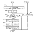
- This division counter Cs is for setting how many times the brake operation amount VD is to be output, and FIG. 3 shows an example of dividing into three.
- step S108 it is determined whether or not the count value of the division counter Cs is smaller than the predetermined division number Ct.
- the count value of the division counter Cs is set to the predetermined division. It is determined whether it is smaller than the number Ct.
- step S110 the divided brake operation amount VDS calculated according to the above equation (2) is output.
- This divided brake operation amount VDS is 1/3 of the brake operation amount VD as shown in FIG.
- step S104 If it is determined in step S104 that the valve timing control period ⁇ T1 is greater than the VTC angle detection period, the process proceeds to step S112, where a brake operation amount VD, for example, a differential operation amount is calculated.
- This brake operation amount VD is expressed by the following equation (3).
- VD ( ⁇ err (current value) ⁇ err (previous value)) / control cycle ⁇ gain (3)
- step S113 the brake operation amount VD is output, and the current valve timing control period ⁇ T1 ends.
- the above-described steps S101 to S111 are repeated every valve timing control period ⁇ T1, thereby dividing the brake operation amount VD into a plurality of divisions (in this example, three divisions) as shown in FIG.
- the brake operation amount VDS is output in a plurality of times according to the VTC position detection intervals t0-t1, t1-t2, t2-t3,... Within each VTC angle detection period.
- FIG. 3 shows an example in which the output is divided into three times between t1-t2 and t2-t3.
- the brake operation amount VD is not divided and is output at the VTC position detection timing.
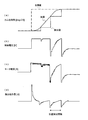
- FIGS. 4A to 4D are waveform diagrams of the cam phase angle, the control voltage, the motor current, and the differential operation amount in the present invention, respectively.
- FIGS. 5A to 5D are comparative examples, and show waveform diagrams of conventional cam phase angles, control voltages, motor currents, and differential manipulated variables (when the manipulated variables are applied collectively).
- the cam phase angle [deg. CA] indicates that the actual value (actual valve timing) rises gradually with respect to the target value (target valve timing) when the engine 1 is running at a low speed.
- a stepped detection value that approaches the target value is obtained for each period.
- the control voltage [V] at this time divides the brake operation amount VD into a plurality of times according to the VTC angle detection cycle as shown in FIG. 4B, and the valve timing control cycle ⁇ T1. Output every time.
- the time during which the brake operation amount VD remains at the peak is shortened.
- the motor current [A] decreases as the effective current decreases, and the current change amount ⁇ I1 becomes smaller than the conventional current change amount ⁇ I2.
- the differential operation amount (brake operation amount) [V] at this time becomes smaller by dividing into a plurality of outputs as shown in FIG. 4 (d) and FIG. 5 (d).
- differential operation amount calculation timing By gradually outputting, it is possible to reduce the effective current and the amount of current change while maintaining the brake function by the differential operation amount. As a result, it is possible to achieve both ensuring of VTC response performance by differential braking and effective current reduction. Further, the calculation load on the ECU 13 can be reduced by dividing the brake operation amount only when the engine is running at a low speed.
- the brake operation amount (differential operation amount) may be divided at a constant rate, the number of divisions may be two or more and less than the number of calculations in the angle detection cycle. At this time, the cycle of the divided output is set to be equal to or longer than the calculation cycle.
- the divided output of the brake operation amount (differential operation amount) can be realized by, for example, a low-pass filter, and the division ratio can be set by a filter coefficient.
- the filter coefficient includes a cut-off frequency and a gain coefficient, and a divided output can be obtained by setting the cut-off frequency and the gain coefficient.
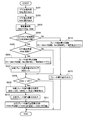
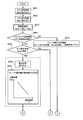
- FIG. 6 is a flowchart showing a procedure for calculating a brake operation amount in the variable valve timing control apparatus for an internal combustion engine according to the second embodiment of the present invention.
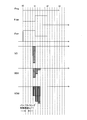
- FIG. 7 is a timing chart of each signal in the flowchart shown in FIG.
- Steps S201 to S206, S212, and S213 are the same as steps S101 to S106, S112, and S113, respectively, and thus description thereof is omitted.
- step S208 it is determined whether or not the integrated value VDSI of the divided brake operation amount VDS is smaller than the brake operation amount VD. If it is smaller, the brake operation amount VD necessary for convergence has not yet been reached, so the process proceeds to step S209.
- step S209 the divided brake operation amount VDS is calculated. This divided brake operation amount VDS is expressed by the following equation (4).
- VDS (VD ⁇ VDSI) ⁇ predetermined division coefficient Ck (4)
- the split brake operation amount VDS is initially large as shown in FIG. 7, and thereafter gradually decreased.
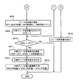
- the integrated value VDSI of the divided brake operation amount VDS is made substantially equal to the brake operation amount VD when the number of divisions is reached, for example.
- step S210 the split brake operation amount VDS is output.
- step S211 the integrated value VDSI of the divided brake operation amount is calculated.
- the integrated value VDSI of the divided brake operation amount is expressed by the following equation (5).
- VDSI (current value) VDSI (previous value) + VDS (current value) (5)
- steps S201 to S213 are repeated every valve timing control period ⁇ T1.
- the brake operation amount VD calculated in step S206 is largely output in the initial stage (first or early timing) within a range in which the operation amount is not saturated, thereby comparing with the first embodiment.
- the brake can be applied quickly and converged to the target value in a short time.
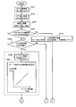
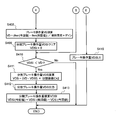
- FIGS. 8 and 9 are flowcharts showing a procedure for calculating the brake operation amount in the variable valve timing control apparatus for an internal combustion engine according to the third embodiment of the present invention.
- FIG. 10 is a timing chart of each signal in the flowcharts shown in FIGS.
- the number of divisions of the brake operation amount VD is switched according to the engine speed RPM.
- Steps S301 to S305 and S308 to S315 in FIG. 8 and FIG. 9 are the same as steps S101 to S113 in the first embodiment, and thus description thereof will be omitted, and only different parts will be described.
- step S306 the engine speed RPM is read.
- step S307 the division number Ct2 of the brake operation amount VD corresponding to the engine speed RPM is calculated. This division number Ct2 is decreased as the engine speed RPM is increased.
- FIG. 10 shows an example in which the division number Ct2 is set to 3 during the VTC position detection timing t1-t2 where the engine speed RPM is low, and the division number Ct2 is set to 2 between t2 and t3.
- the division of the brake operation amount VD can be realized by dividing the brake operation amount VD into a plurality of parts by, for example, a low-pass filter and switching the filter coefficient according to the engine speed RPM.
- the reason why the division number Ct2 is switched according to the VTC angle detection cycle determined from the engine speed RPM is that the optimum division number is different for the following reason.
- the first reason is that, as the engine speed RPM is lower, the VTC angle detection cycle becomes longer, so that the amount of change in the deviation amount is large and the brake operation amount VD calculated at a time is large. Therefore, the division number Ct2 is preferably set to be larger as the engine speed RPM is lower so that the operation amount after the division is not saturated.
- the second reason is that, as the engine speed RPM is lower, the VTC angle detection cycle is longer, so that a period during which the brake operation amount VD can be divided can be made longer and the division number Ct2 can be increased.
- the braking force can be secured, the effective current can be reduced, and the current variation can be reduced.
- FIGS. 4 (a) to 11 (d) show waveform diagrams of the cam phase angle, control voltage, motor current, and differential manipulated variable when the engine speed is lower than those in FIGS. 4 (a) to 4 (d).
- the position detection timing interval differs depending on the engine speed RPM, and is short when the engine speed is high and long when the engine speed is low.
- the position detection timing interval is related to the filter characteristics, and the optimum filter coefficient varies depending on the position detection interval.
- the braking force is secured by the optimal differential operation amount and the effective current is reduced.
- the parameter for switching the number of divisions is not limited to the engine rotation speed RPM, and the rotation speed of the rotating portion in the engine 1, for example, a crank rotation cycle or a VTC angle detection cycle may be used.
- [Fourth Embodiment] 12 and 13 are flowcharts showing the procedure for calculating the brake operation amount in the variable valve timing control apparatus for an internal combustion engine according to the fourth embodiment of the present invention.
- FIG. 14 is a timing chart of each signal in the flowcharts shown in FIGS.
- the fourth embodiment switches the division coefficient of the brake operation amount VD according to the engine speed RPM in the control of the second embodiment described above.
- Steps S401 to S405 and S408 to S415 in FIG. 12 and FIG. 13 are the same as steps S201 to S211 in the second embodiment, and thus description thereof will be omitted, and only different parts will be described.
- step S406 the engine speed RPM is read.
- step S407 a division coefficient Ck2 of the brake operation amount VD corresponding to the engine speed RPM is calculated. This division coefficient Ck2 is increased as the engine speed RPM is increased. Specifically, this can be realized by dividing the brake operation amount VD into a plurality by a low-pass filter and switching the filter coefficient in accordance with the engine speed RPM.
- the reason why the division coefficient Ck2 is switched according to the VTC angle detection cycle determined from the engine speed RPM is that the optimum division coefficient differs for the following reason.
- the first reason is that, as the engine speed RPM is lower, the VTC angle detection cycle is longer, so that the amount of change in the deviation amount is larger and the brake operation amount VD calculated at a time is larger. Therefore, the division coefficient Ck2 is preferably set to be smaller as the engine speed RPM is lower so that the operation amount after the division is not saturated.
- the second reason is that, as the engine speed RPM is lower, the VTC angle detection cycle is longer, so that the period during which the brake operation amount VD can be divided can be made longer and the division coefficient Ck2 can be reduced.
- the division parameter switching parameter is not limited to the engine rotational speed RPM, but the rotational speed of the rotating portion of the engine 1, for example, the crank rotational period or the VTC angle detection period. May be used.
- [Fifth Embodiment] 15 and 16 are flowcharts showing the procedure for calculating the brake operation amount in the variable valve timing control apparatus for an internal combustion engine according to the fifth embodiment of the present invention.
- the division method in addition to the control of the first embodiment described above, the division method is switched according to the environmental temperature T of the electric VTC. The higher the environmental temperature T, the lower the heat resistance limit of the motor. Therefore, the division method is switched to a direction in which the effective current does not increase. For example, the division number is increased as the environmental temperature T is higher. Alternatively, the peak value of the brake operation amount is suppressed.
- Steps S501 to S505 and S508 to S515 are the same as steps S101 to S11 in the first embodiment, and thus description thereof will be omitted and only different parts will be described.
- step S506 the environmental temperature T measured by the temperature sensor 15 is read.
- the environmental temperature T is a temperature that can be correlated with the electric VTC main body, such as the oil temperature, the water temperature, the outside air temperature, the intake air temperature, and the electric VTC main body temperature.
- the division number Ct2 of the brake operation amount VD corresponding to the read environment temperature T is calculated.
- This division number Ct2 is increased as the environmental temperature T increases.
- the division method can be switched in a direction in which the effective current does not increase so as not to exceed the motor heat resistance limit. Specifically, when the environmental temperature T becomes high, by increasing the number of divisions Ct2 of the brake operation amount VD, the effective current to the motor is reduced and the peak value of the brake operation amount is lowered to reduce the motor. Can suppress heat generation.
- FIGS. 17 and 18 are flowcharts showing a procedure for calculating the brake operation amount in the variable valve timing control device for the internal combustion engine according to the sixth embodiment of the present invention.
- the division method in addition to the control of the second embodiment described above, the division method is switched according to the environmental temperature T of the electric VTC. As described above, the higher the environmental temperature T, the lower the motor heat resistance limit. Therefore, the division method is switched to a direction in which the effective current does not increase. For example, the higher the environmental temperature T, the smaller the division factor. Alternatively, the peak value of the brake operation amount is suppressed.
- Steps S601 to S605 and S608 to S615 are the same as steps S201 to S211 in the second embodiment, and thus description thereof will be omitted and only different parts will be described.
- the environmental temperature T measured by the temperature sensor 15 is read.
- the environmental temperature T is a temperature that can be correlated with the electric VTC main body such as the oil temperature, the water temperature, the outside air temperature, the intake air temperature, and the electric VTC main body temperature.
- a division coefficient Ck2 of the brake operation amount VD corresponding to the read environment temperature T is calculated.
- the division coefficient Ck2 is decreased as the environmental temperature T is increased.
- FIG. 19 and 20 are flowcharts showing a procedure for calculating a brake operation amount in the variable valve timing control device for an internal combustion engine according to the seventh embodiment of the present invention.
- the division method is switched according to the power supply voltage VMOT for driving the motor of the electric VTC. If the drive power supply voltage VMOT for driving the motor of the electric VTC is low, the brake operation amount VD is likely to be saturated. Therefore, the division number Ck2 is increased as the drive power supply voltage VMOT is low. Alternatively, the peak value of the brake operation amount VD is suppressed.
- Steps S701 to S705 and S708 to S715 are the same as steps S101 to S111 in the first embodiment, and thus description thereof will be omitted and only different parts will be described.
- step S706 the drive power supply voltage VMOT of the electric VTC measured by the voltmeter 16 is read.
- step S707 the division number Ct2 of the brake operation amount VD corresponding to the read drive power supply voltage VMOT is calculated.
- the division number Ct2 is decreased as the drive power supply voltage VMOT is increased.
- the saturation of the brake operation amount VD can be suppressed by switching the division number Ct2 in accordance with the drive power supply voltage VMOT.
- FIGS. 21 and 22 are flowcharts showing the procedure for calculating the brake operation amount in the variable valve timing control apparatus for an internal combustion engine according to the eighth embodiment of the present invention.
- the division method is switched according to the drive power supply voltage VMOT of the electric VTC. If the drive power supply voltage VMOT of the electric VTC is low, the brake operation amount VD is likely to be saturated. Therefore, the lower the drive power supply voltage VMOT, the smaller the division coefficient Ck2. Alternatively, the peak value of the brake operation amount VD is suppressed.
- Steps S801 to S805 and S808 to S815 are the same as steps S201 to S211 in the second embodiment, and thus description thereof will be omitted and only different parts will be described.
- step S806 the drive power supply voltage VMOT of the electric VTC measured by the voltmeter 16 is read.
- step S807 a division coefficient Ck2 of the brake operation amount VD corresponding to the read drive power supply voltage VMOT is calculated.
- the division coefficient Ck2 is decreased as the drive power supply voltage VMOT is increased.
- the saturation of the brake operation amount VD can be suppressed by switching the division coefficient Ck2 in accordance with the drive power supply voltage VMOT.
- valve timing control by electric VTC depending on the engine temperature such as the starting water temperature or the oil temperature or the environmental condition such as the battery temperature or the battery voltage from the VTC default position at the start (during cranking) or at the time of low engine speed.
- the optimum valve timing can be controlled. Therefore, it is possible to achieve both the fuel efficiency effect due to the slow closing of the intake valve and the starting quality.
- SYMBOLS 1 Engine (internal combustion engine), 6 ... Variable valve timing mechanism (VTC), 9 ... Crank angle sensor, 12 ... Cam angle sensor, 13 ... ECU (calculation means), 14 ... Aero flow meter, 15 ... Temperature sensor, 16 ... Voltmeter, VD ... Brake operation amount, VDS ... Division brake operation amount, Ct, Ct2 ... Number of divisions, Ck, Ck2 ... Division coefficient
Landscapes
- Engineering & Computer Science (AREA)
- Chemical & Material Sciences (AREA)
- Combustion & Propulsion (AREA)
- Mechanical Engineering (AREA)
- General Engineering & Computer Science (AREA)
- Output Control And Ontrol Of Special Type Engine (AREA)
- Valve Device For Special Equipments (AREA)
Abstract
La présente invention concerne : un dispositif de contrôle de distribution variable pour modifier la distribution d'un moteur à combustion interne ; et un procédé de contrôle correspondant. L'ampleur de l'opération pour contrôler la distribution est calculée et l'ampleur de l'opération calculée selon un moment de détection de position pour un mécanisme de distribution variable est divisée et émise pendant un laps de temps jusqu'au prochain moment de détection de position.
Priority Applications (3)
| Application Number | Priority Date | Filing Date | Title |
|---|---|---|---|
| CN201480002291.6A CN104603426B (zh) | 2013-06-06 | 2014-03-07 | 内燃机的可变气门正时控制装置及控制方法 |
| US14/432,284 US9410488B2 (en) | 2013-06-06 | 2014-03-07 | Variable valve timing control device for internal combustion engine, and control method |
| DE112014002734.0T DE112014002734T5 (de) | 2013-06-06 | 2014-03-07 | Variable Ventilsteuerungsvorrichtung für einen Verbrennungsmotor und Steuerungsverfahren |
Applications Claiming Priority (2)
| Application Number | Priority Date | Filing Date | Title |
|---|---|---|---|
| JP2013-120036 | 2013-06-06 | ||
| JP2013120036A JP6018019B2 (ja) | 2013-06-06 | 2013-06-06 | 内燃機関の可変バルブタイミング制御装置 |
Publications (1)
| Publication Number | Publication Date |
|---|---|
| WO2014196237A1 true WO2014196237A1 (fr) | 2014-12-11 |
Family
ID=52007893
Family Applications (1)
| Application Number | Title | Priority Date | Filing Date |
|---|---|---|---|
| PCT/JP2014/055933 Ceased WO2014196237A1 (fr) | 2013-06-06 | 2014-03-07 | Dispositif de contrôle de distribution variable pour moteur à combustion interne, et procédé de contrôle |
Country Status (5)
| Country | Link |
|---|---|
| US (1) | US9410488B2 (fr) |
| JP (1) | JP6018019B2 (fr) |
| CN (1) | CN104603426B (fr) |
| DE (1) | DE112014002734T5 (fr) |
| WO (1) | WO2014196237A1 (fr) |
Families Citing this family (1)
| Publication number | Priority date | Publication date | Assignee | Title |
|---|---|---|---|---|
| KR20240075002A (ko) * | 2022-11-16 | 2024-05-29 | 현대자동차주식회사 | 모터 발열 최소화 장치 및 최소화 방법 |
Citations (6)
| Publication number | Priority date | Publication date | Assignee | Title |
|---|---|---|---|---|
| JPH10318004A (ja) * | 1997-05-15 | 1998-12-02 | Unisia Jecs Corp | 内燃機関のバルブタイミング制御装置 |
| JP2005233153A (ja) * | 2004-02-23 | 2005-09-02 | Hitachi Ltd | 可変バルブタイミング機構の制御装置 |
| JP2007162479A (ja) * | 2005-12-09 | 2007-06-28 | Toyota Motor Corp | 内燃機関のバルブ特性制御装置 |
| JP2008190385A (ja) * | 2007-02-02 | 2008-08-21 | Mitsubishi Electric Corp | 内燃機関制御装置 |
| JP2009197591A (ja) * | 2008-02-19 | 2009-09-03 | Hitachi Ltd | 内燃機関のバルブタイミング制御装置 |
| JP2010180766A (ja) * | 2009-02-05 | 2010-08-19 | Hitachi Automotive Systems Ltd | エンジンの制御装置 |
Family Cites Families (2)
| Publication number | Priority date | Publication date | Assignee | Title |
|---|---|---|---|---|
| JP4123127B2 (ja) | 2002-10-25 | 2008-07-23 | 株式会社デンソー | 内燃機関の可変バルブタイミング制御装置 |
| US20070283925A1 (en) * | 2006-05-19 | 2007-12-13 | Denso Corporation | Controller for vane-type variable valve timing adjusting mechanism |
-
2013
- 2013-06-06 JP JP2013120036A patent/JP6018019B2/ja not_active Expired - Fee Related
-
2014
- 2014-03-07 CN CN201480002291.6A patent/CN104603426B/zh not_active Expired - Fee Related
- 2014-03-07 WO PCT/JP2014/055933 patent/WO2014196237A1/fr not_active Ceased
- 2014-03-07 DE DE112014002734.0T patent/DE112014002734T5/de not_active Withdrawn
- 2014-03-07 US US14/432,284 patent/US9410488B2/en not_active Expired - Fee Related
Patent Citations (6)
| Publication number | Priority date | Publication date | Assignee | Title |
|---|---|---|---|---|
| JPH10318004A (ja) * | 1997-05-15 | 1998-12-02 | Unisia Jecs Corp | 内燃機関のバルブタイミング制御装置 |
| JP2005233153A (ja) * | 2004-02-23 | 2005-09-02 | Hitachi Ltd | 可変バルブタイミング機構の制御装置 |
| JP2007162479A (ja) * | 2005-12-09 | 2007-06-28 | Toyota Motor Corp | 内燃機関のバルブ特性制御装置 |
| JP2008190385A (ja) * | 2007-02-02 | 2008-08-21 | Mitsubishi Electric Corp | 内燃機関制御装置 |
| JP2009197591A (ja) * | 2008-02-19 | 2009-09-03 | Hitachi Ltd | 内燃機関のバルブタイミング制御装置 |
| JP2010180766A (ja) * | 2009-02-05 | 2010-08-19 | Hitachi Automotive Systems Ltd | エンジンの制御装置 |
Also Published As
| Publication number | Publication date |
|---|---|
| US20150233306A1 (en) | 2015-08-20 |
| US9410488B2 (en) | 2016-08-09 |
| JP2014238026A (ja) | 2014-12-18 |
| JP6018019B2 (ja) | 2016-11-02 |
| CN104603426A (zh) | 2015-05-06 |
| DE112014002734T5 (de) | 2016-03-03 |
| CN104603426B (zh) | 2017-03-15 |
Similar Documents
| Publication | Publication Date | Title |
|---|---|---|
| RU2639826C2 (ru) | Способ управления регулятором давления наддува турбонагнетателя двигателя и способ управления турбонагнетателем двигателя | |
| JP4919945B2 (ja) | エンジンのスライディングモード制御による空燃比制御方法、及びその方法を備えた燃料制御装置 | |
| JP4989509B2 (ja) | 内燃機関のバルブタイミング制御装置 | |
| JP6018019B2 (ja) | 内燃機関の可変バルブタイミング制御装置 | |
| KR20130107222A (ko) | 가변 밸브 타이밍 기구의 제어 장치 및 가변 밸브 타이밍 기구의 제어 방법 | |
| RU2695238C2 (ru) | Способ для двигателя (варианты) | |
| JP6446081B2 (ja) | 内燃機関の制御装置 | |
| CN102859157A (zh) | 用于控制可变气门系统的方法和装置 | |
| JP5720855B2 (ja) | 内燃機関の制御装置 | |
| JP4852992B2 (ja) | 内燃機関の制御装置 | |
| JP4901677B2 (ja) | 可変動弁機構の制御装置 | |
| JP5015974B2 (ja) | 可変動弁機構の制御装置 | |
| JP4581984B2 (ja) | 内燃機関のバルブ特性制御装置 | |
| JP5229118B2 (ja) | 内燃機関トルク制御装置 | |
| JP6371040B2 (ja) | 内燃機関の制御装置および制御方法 | |
| JP4542000B2 (ja) | 内燃機関の可変バルブの制御装置および制御方法 | |
| JP2007218132A (ja) | 内燃機関の制御装置 | |
| JP6060812B2 (ja) | エンジン制御装置 | |
| JP4618039B2 (ja) | 内燃機関システム | |
| JP6689778B2 (ja) | 可変バルブタイミング装置の制御装置及び制御方法 | |
| JP5279759B2 (ja) | 内燃機関の制御装置 | |
| JP5983580B2 (ja) | 内燃機関の制御装置 | |
| JP5844170B2 (ja) | 内燃機関の制御装置 | |
| JP2007064022A (ja) | 制御装置 | |
| JP2010025046A (ja) | 内燃機関の制御システムおよび制御方法 |
Legal Events
| Date | Code | Title | Description |
|---|---|---|---|
| 121 | Ep: the epo has been informed by wipo that ep was designated in this application |
Ref document number: 14808238 Country of ref document: EP Kind code of ref document: A1 |
|
| WWE | Wipo information: entry into national phase |
Ref document number: 14432284 Country of ref document: US |
|
| WWE | Wipo information: entry into national phase |
Ref document number: 112014002734 Country of ref document: DE |
|
| 122 | Ep: pct application non-entry in european phase |
Ref document number: 14808238 Country of ref document: EP Kind code of ref document: A1 |