WO2014196403A1 - シールリング - Google Patents
シールリング Download PDFInfo
- Publication number
- WO2014196403A1 WO2014196403A1 PCT/JP2014/063870 JP2014063870W WO2014196403A1 WO 2014196403 A1 WO2014196403 A1 WO 2014196403A1 JP 2014063870 W JP2014063870 W JP 2014063870W WO 2014196403 A1 WO2014196403 A1 WO 2014196403A1
- Authority
- WO
- WIPO (PCT)
- Prior art keywords
- seal ring
- peripheral surface
- inner peripheral
- fluid pressure
- shaft
- Prior art date
- Legal status (The legal status is an assumption and is not a legal conclusion. Google has not performed a legal analysis and makes no representation as to the accuracy of the status listed.)
- Ceased
Links
Images











Classifications
-
- F—MECHANICAL ENGINEERING; LIGHTING; HEATING; WEAPONS; BLASTING
- F16—ENGINEERING ELEMENTS AND UNITS; GENERAL MEASURES FOR PRODUCING AND MAINTAINING EFFECTIVE FUNCTIONING OF MACHINES OR INSTALLATIONS; THERMAL INSULATION IN GENERAL
- F16J—PISTONS; CYLINDERS; SEALINGS
- F16J9/00—Piston-rings, e.g. non-metallic piston-rings, seats therefor; Ring sealings of similar construction
- F16J9/12—Details
- F16J9/14—Joint-closures
-
- F—MECHANICAL ENGINEERING; LIGHTING; HEATING; WEAPONS; BLASTING
- F16—ENGINEERING ELEMENTS AND UNITS; GENERAL MEASURES FOR PRODUCING AND MAINTAINING EFFECTIVE FUNCTIONING OF MACHINES OR INSTALLATIONS; THERMAL INSULATION IN GENERAL
- F16J—PISTONS; CYLINDERS; SEALINGS
- F16J15/00—Sealings
- F16J15/16—Sealings between relatively-moving surfaces
- F16J15/164—Sealings between relatively-moving surfaces the sealing action depending on movements; pressure difference, temperature or presence of leaking fluid
-
- F—MECHANICAL ENGINEERING; LIGHTING; HEATING; WEAPONS; BLASTING
- F16—ENGINEERING ELEMENTS AND UNITS; GENERAL MEASURES FOR PRODUCING AND MAINTAINING EFFECTIVE FUNCTIONING OF MACHINES OR INSTALLATIONS; THERMAL INSULATION IN GENERAL
- F16J—PISTONS; CYLINDERS; SEALINGS
- F16J15/00—Sealings
- F16J15/44—Free-space packings
- F16J15/441—Free-space packings with floating ring
-
- F—MECHANICAL ENGINEERING; LIGHTING; HEATING; WEAPONS; BLASTING
- F16—ENGINEERING ELEMENTS AND UNITS; GENERAL MEASURES FOR PRODUCING AND MAINTAINING EFFECTIVE FUNCTIONING OF MACHINES OR INSTALLATIONS; THERMAL INSULATION IN GENERAL
- F16J—PISTONS; CYLINDERS; SEALINGS
- F16J15/00—Sealings
- F16J15/44—Free-space packings
- F16J15/443—Free-space packings provided with discharge channels
Definitions
- the present invention relates to a seal ring that seals an annular gap between a shaft and a shaft hole of a housing.
- FIG. 19 is a schematic cross-sectional view showing a use state of a seal ring according to a conventional example.
- the seal ring 300 according to the conventional example is mounted in an annular groove 510 provided on the outer periphery of the shaft 500.
- the seal ring 300 is in close contact with the inner peripheral surface of the shaft hole of the housing 600 through which the shaft 500 is inserted, and is slidably in contact with the side wall surface of the annular groove 510.
- the annular gap between the holes is sealed.
- the seal ring 300 is provided with a pair of recesses 320 extending in the circumferential direction on the inner peripheral side of both side surfaces. Accordingly, an effective pressure receiving region when the seal ring 300 is pressed in the axial direction from the high pressure side (H) to the low pressure side (L) by the fluid to be sealed is a region indicated by A in FIG. That is, the effective pressure receiving region A is a region in the radial direction of the portion 310 where the recess 320 is not provided on the side surface of the seal ring 300. This is because, in the region where the recess 320 is provided, fluid pressure acts from both sides in the axial direction, and the force applied to the seal ring 300 in the axial direction is offset. The area over the entire circumference of the pressure receiving region A is an effective pressure receiving area in the axial direction.
- an effective pressure receiving region when the seal ring 300 is pressed radially outward from the inner peripheral surface side to the outer peripheral surface side by the fluid to be sealed is a region indicated by B in FIG. That is, the thickness in the axial direction of the seal ring 300 is an effective pressure receiving region B. The area over the entire circumference of the pressure receiving region B is the pressure receiving area in the radial direction.
- the contact region of the seal ring 300 with respect to the side wall surface of the annular groove 510 is a region indicated by C in FIG. That is, the seal ring 300 is a side surface on the low-pressure side (L), and only the portion excluding the portion exposed to the gap between the shaft 500 and the housing 600 out of the portion 310 where the recess 320 is not provided. It contacts the side wall surface of the annular groove 510. Therefore, the contact area C in the seal ring 300 is affected by the size of the gap between the shaft 500 and the housing 600. Therefore, depending on the use environment, the contact area of the seal ring 300 with respect to the side wall surface of the annular groove 510 may be excessively reduced, and the sealing performance may be deteriorated. Further, there is a problem that the contact area changes depending on the use environment and the sealing performance is not stable.
- An object of the present invention is to provide a seal ring that achieves stabilization of sealing performance while reducing rotational torque.
- the present invention employs the following means in order to solve the above problems.
- the seal ring of the present invention is Fluid pressure in a region to be sealed is mounted in an annular groove provided on the outer periphery of the shaft and configured to seal the annular clearance between the relatively rotating shaft and the housing so that the fluid pressure changes.
- a seal ring for holding In the seal ring that is in close contact with the side wall surface on the low pressure side in the annular groove and slides against the inner peripheral surface of the shaft hole through which the shaft in the housing is inserted,
- On the outer peripheral surface side On the outer peripheral surface side, a pair of recesses extending in the circumferential direction are provided on both sides in the width direction, The distance from the one side surface of the convex portion located between the pair of recesses to the other side surface of the seal ring, and the distance from the other side surface of the convex portion to the one side surface of the seal ring, By being set shorter than the distance from the inner peripheral surface of the seal ring to the outer peripheral surface of the convex portion, The effective pressure receiving area from the inner peripheral surface side that contributes
- the seal ring of another invention is Fluid pressure in a region to be sealed is mounted in an annular groove provided on the outer periphery of the shaft and configured to seal the annular clearance between the relatively rotating shaft and the housing so that the fluid pressure changes.
- a seal ring for holding In the seal ring that is in close contact with the side wall surface on the low pressure side in the annular groove and slides against the inner peripheral surface of the shaft hole through which the shaft in the housing is inserted,
- On the outer surface side On the outer surface side, A recess provided in the center in the width direction and extending in the circumferential direction; A pair of convex portions provided on both sides via the concave portion and sliding with respect to the inner peripheral surface of the shaft hole; And having By having a through hole that is provided so as to reach the bottom surface of the concave portion from the inner peripheral surface side and that allows the fluid to be sealed to be introduced into the concave portion from the inner peripheral surface side, The effective pressure receiving area from the inner peripheral surface side that contributes to the force pressed against the
- the seal ring of another invention is Fluid pressure in a region to be sealed is mounted in an annular groove provided on the outer periphery of the shaft and configured to seal the annular clearance between the relatively rotating shaft and the housing so that the fluid pressure changes.
- a seal ring for holding In the seal ring that is in close contact with the side wall surface on the low pressure side in the annular groove and slides against the inner peripheral surface of the shaft hole through which the shaft in the housing is inserted,
- the portion that slides with respect to the inner peripheral surface of the shaft hole is constituted by a convex portion that is formed to extend in the circumferential direction while changing its position alternately between the high pressure side and the low pressure side,
- the effective pressure receiving area from the inner peripheral surface side that contributes to the force pressed against the inner peripheral surface of the shaft hole by the fluid pressure is pressed against the side wall surface on the low pressure side in the annular groove by the fluid pressure. It is comprised so that it may become narrower than the effective pressure receiving area from the side surface side which contributes to the force to
- the outer peripheral surface of the convex portion in the seal ring can be slid more reliably with respect to the inner peripheral surface of the shaft hole.
- the area of the sliding portion can be stabilized regardless of the size of the annular gap between the shaft and the housing. Accordingly, it is possible to stabilize the sealing performance.
- sliding resistance can be reduced and rotational torque can be reduced by sliding the convex part of the outer peripheral surface of the seal ring more reliably.
- FIG. 1 is a view of a seal ring according to a first embodiment of the present invention as viewed from the outer peripheral surface side.
- FIG. 2 is a side view of the seal ring according to the first embodiment of the present invention.
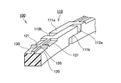
- FIG. 3 is a partially broken perspective view of the seal ring according to the first embodiment of the present invention.
- FIG. 4 is a schematic cross-sectional view showing a usage state of the seal ring according to the first embodiment of the present invention.
- FIG. 5 is a view of the seal ring according to the second embodiment of the present invention as viewed from the outer peripheral surface side.
- FIG. 6 is a partially broken perspective view of a seal ring according to Embodiment 2 of the present invention.
- FIG. 1 is a view of a seal ring according to a first embodiment of the present invention as viewed from the outer peripheral surface side.
- FIG. 2 is a side view of the seal ring according to the first embodiment of the present invention.
- FIG. 3 is a partially broken perspective view
- FIG. 7 is a partially broken sectional view of the seal ring according to the third embodiment of the present invention as viewed from the outer peripheral surface side.
- FIG. 8 is a side view of a seal ring according to Embodiment 3 of the present invention.
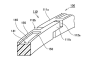
- FIG. 9 is a partially broken perspective view of a seal ring according to Embodiment 3 of the present invention.
- FIG. 10 is a schematic cross-sectional view showing a usage state of the seal ring according to the third embodiment of the present invention.
- FIG. 11 is a schematic cross-sectional view showing a usage state of the seal ring according to the third embodiment of the present invention.
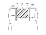
- FIG. 12 is a schematic cross-sectional view showing a usage state of the seal ring according to the third embodiment of the present invention.
- FIG. 13 is a partially broken cross-sectional view of a seal ring according to Embodiment 4 of the present invention as viewed from the outer peripheral surface side.
- FIG. 14 is a partial view of the seal ring according to the fourth embodiment of the present invention as viewed from the outer peripheral surface side.
- FIG. 15 is a side view of a seal ring according to Embodiment 4 of the present invention.
- FIG. 16 is typical sectional drawing which shows the use condition of the seal ring which concerns on Example 4 of this invention.
- FIG. 17 is typical sectional drawing which shows the use condition of the seal ring which concerns on Example 4 of this invention.
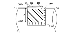
- FIG. 18 is a schematic cross-sectional view showing a usage state of the seal ring according to Embodiment 4 of the present invention.
- FIG. 19 is a schematic cross-sectional view showing a use state of a seal ring according to a conventional example.
- the seal ring according to the present embodiment is used for sealing an annular gap between a relatively rotating shaft and a housing in order to maintain hydraulic pressure in a transmission such as an AT or CVT for automobiles. It is used.
- high pressure side means a side that becomes high when differential pressure occurs on both sides of the seal ring
- low pressure side means that differential pressure occurs on both sides of the seal ring. This means the side that is at low pressure.
- Example 1 A seal ring according to Embodiment 1 of the present invention will be described with reference to FIGS.
- the seal ring 100 is mounted in an annular groove 510 provided on the outer periphery of the shaft 500, and rotates relative to the shaft 500 and the housing 600 (the inner periphery of the shaft hole through which the shaft 500 is inserted.
- the annular gap between the first and second surfaces is sealed.
- the seal ring 100 maintains the fluid pressure in the seal target region configured so that the fluid pressure (hydraulic pressure in the present embodiment) changes.
- the fluid pressure in the region on the right side in FIG. 4 is configured to change, and the seal ring 100 plays a role of maintaining the fluid pressure in the region to be sealed on the right side in the diagram. Yes.
- the fluid pressure in the seal target area is low and no load is applied.
- the fluid pressure in the seal target area increases.
- the seal ring 100 is made of a resin material such as polyetheretherketone (PEEK), polyphenylene sulfide (PPS), polytetrafluoroethylene (PTFE). Further, the peripheral length of the outer peripheral surface of the seal ring 100 is configured to be shorter than the peripheral length of the inner peripheral surface of the shaft hole of the housing 600, and is configured not to have a tightening margin.
- PEEK polyetheretherketone
- PPS polyphenylene sulfide
- PTFE polytetrafluoroethylene
- the seal ring 100 is provided with an abutment portion 110 at one place in the circumferential direction.
- a pair of recesses 130 extending in the circumferential direction are provided on both sides in the width direction on the outer peripheral surface side of the seal ring 100.
- a protrusion 120 that slides on the inner peripheral surface of the shaft hole of the housing 600 is provided.
- the bottom surfaces of the pair of recesses 130 are configured to be concentric with the inner peripheral surface of the seal ring 100.
- the side surface of the convex portion 120 is configured to be perpendicular to the bottom surface of the concave portion 130.
- the seal ring 100 according to the present embodiment is formed with the convex portion 120 obtained by providing the above-described joint portion 110, the pair of concave portions 130, and the pair of concave portions 130 with respect to the annular member having a rectangular cross section. It is the structure which was made. However, this is merely an explanation of the shape, and does not necessarily mean that the annular member having a rectangular cross section is used as a raw material to perform the processing for forming these parts. Of course, after forming an annular member having a rectangular cross section, each part can be obtained by cutting. However, for example, after forming the joint portion 110 in advance, the recess 130 may be obtained by cutting, and the manufacturing method is not particularly limited.
- the joint portion 110 employs a so-called special step cut that is cut in a step shape when viewed from either the outer peripheral surface side or both side wall surfaces.
- the first fitting convex portion 111a and the first fitting concave portion 112a are provided on the outer peripheral side on one side through the cutting portion, and the first outer peripheral side on the other side is provided with the first.
- a second fitting concave portion 112b into which the fitting convex portion 111a is fitted and a second fitting convex portion 111b to be fitted into the first fitting concave portion 112a are provided.
- the special step cut is a known technique, a detailed description thereof is omitted, but it has a characteristic of maintaining a stable sealing performance even if the circumference of the seal ring 100 is changed due to thermal expansion and contraction.
- the case of the special step cut is shown as an example of the abutment portion 110, but the abutment portion 110 is not limited to this, and a straight cut, a bias cut, a step cut, or the like can also be adopted.
- a low-elasticity material such as PTFE
- the end portion may be provided without providing the joint portion 110.
- the pair of recesses 130 is formed over the entire circumference except for the vicinity of the joint portion 110.
- the part where the concave portion 130 in the vicinity of the joint portion 110 is not provided and the outer peripheral surface of the convex portion 120 are the same surface.
- an annular continuous seal surface on the outer peripheral surface side of the seal ring 100 is formed. That is, on the outer peripheral surface of the seal ring 100, only the outer peripheral surface of the convex portion 120 slides with respect to the inner peripheral surface of the shaft hole in a region excluding the vicinity of the joint portion 110.
- the convex part 120 when employ
- the width of the convex portion 120 although the torque can be reduced as the width becomes narrower, if the width is made too narrow, the sealing performance and the durability are deteriorated. Therefore, it is desirable to reduce the width as much as possible to the extent that the sealing performance and durability can be maintained according to the use environment and the like.
- the width of the convex portion 120 may be set to about 0.3 mm or more and 0.7 mm or less.
- the distance (corresponding to the length of the region B) from one side surface of the convex portion 120 to the other side surface of the seal ring 100, and the other side of the convex portion 120 is set shorter than the distance from the inner peripheral surface of the seal ring 100 to the outer peripheral surface of the convex portion 120 (corresponding to the length of the region A) ( (See FIG. 4).
- the distance from one side surface of the convex portion 120 to the other side surface of the seal ring 100 and the distance from the other side surface of the convex portion 120 to the one side surface of the seal ring 100 are equal.
- the region B can also be referred to as a region from the high pressure side (H) side surface of the protrusion 120 to the low pressure side (L) side surface of the seal ring 100 when the seal ring 100 is used (see FIG. 4).
- the effective pressure receiving area from the inner peripheral surface side that contributes to the force with which the seal ring 100 is pressed against the inner peripheral surface of the shaft hole by the fluid pressure This is narrower than the effective pressure receiving area from the side surface that contributes to the force pressed against the side wall surface on the low pressure side in the annular groove 510 by the fluid pressure.
- FIG. 4 shows a state in which the engine is started and a differential pressure is generated via the seal ring 100 (a state in which the pressure on the right side in the drawing is higher than the pressure on the left side).
- the seal ring 100 is formed in the annular groove 510 on the left side wall surface in FIG. It can be in a state away from the peripheral surface.
- the seal ring 100 When the engine is started and the differential pressure is generated, the seal ring 100 is in close contact with the side wall surface on the low pressure side (L) of the annular groove 510 and slides against the inner peripheral surface of the shaft hole. (See FIG. 4).
- the direction in which the fluid pressure acts from the inner peripheral surface side and the direction in which the fluid pressure acts from the outer peripheral surface side are opposite to each other.
- the arrows in FIG. 4 indicate how the fluid pressure acts on the seal ring 100.
- the length of the region B shown in FIG. 4 is set shorter than the length of the region A.
- the region A is an effective pressure receiving region when the seal ring 100 is pressed in the axial direction from the high pressure side (H) to the low pressure side (L) by the fluid to be sealed. Further, the area over the entire circumference of the pressure receiving region A is an effective pressure receiving area in the axial direction.
- the region B is an effective pressure receiving region when the seal ring 100 is pressed radially outward from the inner peripheral surface side toward the outer peripheral surface side by the fluid to be sealed. This is because, as described above, in the region where the recess 130 is provided, fluid pressure acts from both sides in the radial direction, and the force applied to the seal ring 100 in the radial direction is offset.
- the area over the entire circumference of the pressure receiving region B is an effective pressure receiving area in the radial direction.
- the effective pressure receiving area (pressure receiving area) for the seal ring 100 is smaller in the direction toward the radially outer side than in the axial direction. Therefore, the outer peripheral surface of the convex part 120 in the seal ring 100 can be slid more reliably with respect to the inner peripheral surface of the shaft hole. Thereby, irrespective of the size of the annular gap between the shaft 500 and the housing 600, the area of the sliding portion can be stabilized. Accordingly, it is possible to stabilize the sealing performance. Moreover, sliding resistance can be reduced and rotational torque can be reduced by sliding the part of the convex part 120 more reliably among the outer peripheral surfaces of the seal ring 100.
- a lubricating film here, an oil film
- the sliding torque can be further reduced. This is because, when sliding between the outer peripheral surface of the seal ring 100 and the inner peripheral surface of the shaft hole, a wedge effect is exhibited in a minute gap portion between them.
- the pair of recesses 130 is formed over the entire circumference except for the vicinity of the joint portion 110.
- the recess 130 is provided over a wide range of the outer peripheral surface of the seal ring 100, so that the sliding area between the seal ring 100 and the inner peripheral surface of the shaft hole of the housing 600 is made possible. And the sliding torque can be greatly reduced.
- the reduction of the sliding torque can be realized, so that the heat generated by the sliding can be suppressed, and the seal ring 100 according to the present embodiment can be suitably used even under high-speed and high-pressure environmental conditions.
- a soft material such as aluminum can be used as the material of the shaft 500.
- the seal ring 100 according to the present embodiment has a symmetrical shape with respect to the center plane in the width direction, the mounting direction is a concern when the seal ring 100 is mounted in the annular groove 510. There is no need. Moreover, the above excellent effects are exhibited even in an environment where the relationship between the high pressure side (H) and the low pressure side (L) is switched.
- the side surface of the convex portion 120 is configured to be perpendicular to the bottom surface of the concave portion 130.
- the side surface of the convex portion 120 is inclined such as a tapered surface so that the width of the convex portion 120 becomes narrower toward the outer peripheral surface side.
- the fluid to be sealed may blow through the gap between the outer peripheral surface of the convex portion 120 and the inner peripheral surface of the shaft hole when a differential pressure is suddenly generated. Therefore, it is desirable that the side surface of the convex portion 120 be perpendicular to the bottom surface of the concave portion 130.
- Example 2 shows a second embodiment of the present invention.
- a configuration in which a plurality of ribs are provided in a pair of recesses is shown with respect to the configuration shown in the first embodiment. Since other configurations and operations are the same as those in the first embodiment, the same components are denoted by the same reference numerals, and the description thereof is omitted as appropriate.
- the seal ring 100 also includes the joint portion 110, the pair of concave portions 130, and the convex portion 120, as in the first embodiment.
- the joint part 110 the recessed part 130, and the convex part 120, since it is the same structure as the seal ring which concerns on the said Example 1, the description is abbreviate
- the joint part 110 although the case where a special step cut is employ
- a plurality of ribs 121 provided so as to be connected to the convex portion 120 are provided in the pair of concave portions 130.
- the same effects as those of the seal ring 100 according to the first embodiment can be obtained.
- the rigidity of the seal ring 100 is increased, and in particular, the strength in the twisting direction is increased. Therefore, even in an environment where the differential pressure increases, the deformation of the seal ring 100 is suppressed, and the sealing performance is stably exhibited.
- Example 3 7 to 12 show Embodiment 3 of the present invention.
- the same components are denoted by the same reference numerals, and the description thereof is omitted as appropriate.
- the seal ring 100 is mounted in an annular groove 510 provided on the outer periphery of the shaft 500, and rotates relative to the shaft 500 and the housing 600 (the inner periphery of the shaft hole through which the shaft 500 is inserted.
- the annular gap between the first and second surfaces is sealed.
- the seal ring 100 maintains the fluid pressure in the seal target region configured so that the fluid pressure (hydraulic pressure in the present embodiment) changes.
- the fluid pressure in the region on the right side in FIGS. 10 to 12 is configured to change, and the seal ring 100 serves to maintain the fluid pressure in the region to be sealed on the right side in the diagram. Is responsible.
- the fluid pressure in the seal target area is low and no load is applied.
- the fluid pressure in the seal target area increases.
- the seal ring 100 is made of a resin material such as polyetheretherketone (PEEK), polyphenylene sulfide (PPS), polytetrafluoroethylene (PTFE). Further, the peripheral length of the outer peripheral surface of the seal ring 100 is configured to be shorter than the peripheral length of the inner peripheral surface of the shaft hole of the housing 600, and is configured not to have a tightening margin.
- PEEK polyetheretherketone
- PPS polyphenylene sulfide
- PTFE polytetrafluoroethylene
- the seal ring 100 is provided with an abutment portion 110 at one place in the circumferential direction. Further, on the outer peripheral surface side of the seal ring 100, a concave portion 140 provided in the center in the width direction and extending in the circumferential direction is provided on both sides via the concave portion 140, and is provided on the inner peripheral surface of the shaft hole of the housing 600. A pair of convex portions 150 are provided. Further, the seal ring 100 is provided so as to extend from the inner peripheral surface side to the bottom surface of the concave portion 140 and allows a fluid to be sealed (here, oil) to be introduced into the concave portion 140 from the inner peripheral surface side. Are provided. The bottom surface of the recess 140 is configured as a surface concentric with the inner peripheral surface of the seal ring 100.
- the seal ring 100 has a configuration in which the above-described joint portion 110, the concave portion 140, the through hole 141, and the pair of convex portions 150 are formed on an annular member having a rectangular cross section.
- this is merely an explanation of the shape, and does not necessarily mean that the annular member having a rectangular cross section is used as a raw material to perform the processing for forming these parts.
- each part can be obtained by cutting.
- the concave portion 140, the through hole 141, and the pair of convex portions 150 may be obtained by cutting, and the manufacturing method is not particularly limited.
- the joint portion 110 employs a so-called special step cut that is cut in a step shape when viewed from either the outer peripheral surface side or both side wall surfaces. Since the abutment portion 110 is as described in the first embodiment, the description thereof is omitted.
- the recess 140 is formed over the entire circumference except for the vicinity of the joint portion 110.
- an annular continuous seal surface on the outer peripheral surface side of the seal ring 100 is formed. That is, on the outer peripheral surface of the seal ring 100, only the outer peripheral surfaces of the pair of convex portions 150 slide with respect to the inner peripheral surface of the shaft hole in the region excluding the vicinity of the joint portion 110.
- adopting the structure which does not provide the opening part 110 a pair of convex part 150 also becomes cyclic
- the depth of the recess 140 As for the depth of the recess 140, the shallower the rigidity of the pair of protrusions 150 becomes higher. On the other hand, since the pair of convex portions 150 are worn by sliding, the depth of the concave portion 140 becomes shallower with time. Therefore, if the depth of the recess 140 becomes too shallow, it becomes impossible to introduce the fluid. Therefore, it is desirable to set the initial depth of the concave portion 140 in consideration of both the rigidity and maintaining the introduction of the fluid even if wear with time progresses. For example, when the thickness of the seal ring 100 is 1.7 mm, the depth of the recess 140 may be set to about 0.1 mm or more and 0.3 mm or less.
- the width of the pair of convex portions 150 although the torque can be reduced as the width becomes narrower, if the width is made too narrow, the sealing performance and the durability are deteriorated. Therefore, it is desirable to reduce the width as much as possible to the extent that the sealing performance and durability can be maintained according to the use environment and the like.
- the width of the pair of convex portions 150 may be set to about 0.3 mm or more and 0.7 mm or less.
- the length obtained by adding the widths of the pair of convex portions 150 (corresponding to the lengths of the region B1 and the region B2 in FIG. 11) It is set to be shorter than the distance from the peripheral surface to the outer peripheral surface of the convex portion 150 (corresponding to the length of the region A in FIG. 11). Note that the length of the region B1 and the length of the region B2 are set equal.
- the effective pressure received from the inner peripheral surface side that contributes to the force with which the seal ring 100 is pressed against the inner peripheral surface of the shaft hole by the fluid pressure is narrower than the effective pressure receiving area from the side surface that contributes to the force pressed against the side wall surface on the low pressure side in the annular groove 510 by the fluid pressure.
- FIG. 10 shows a state in which the engine is stopped and there is no differential pressure in the left and right regions (or almost no differential pressure) via the seal ring 100 and no load is applied.
- the seal ring 100 in FIG. 10 corresponds to the DD cross section in FIG. 11 and 12 show a state in which the engine is started and the fluid pressure in the right region is higher than the left region through the seal ring 100.
- 11 corresponds to the EE cross section in FIG. 8
- the seal ring 100 in FIG. 12 corresponds to the DD cross section in FIG.
- the seal ring 100 is formed in the annular groove 510 on the left side wall surface in FIG. It can be in a state away from the peripheral surface.
- the seal ring 100 When the engine is started and the differential pressure is generated, the seal ring 100 is in close contact with the side wall surface on the low pressure side (L) of the annular groove 510 and slides against the inner peripheral surface of the shaft hole. (See FIGS. 11 and 12).
- FIG.11 and FIG.12 has shown a mode that fluid pressure acts with respect to the seal ring 100.
- FIG. Thereby, in the seal ring 100 according to the present embodiment, an increase in pressure toward the outer peripheral surface by the seal ring 100 accompanying an increase in fluid pressure can be suppressed, and a sliding torque can be suppressed low.
- the sum of the lengths of the region B1 and the region B2 illustrated in FIG. 11 is set to be shorter than the length of the region A.
- the region A is an effective pressure receiving region when the seal ring 100 is pressed in the axial direction from the high pressure side (H) to the low pressure side (L) by the fluid to be sealed. Further, the area over the entire circumference of the pressure receiving region A is an effective pressure receiving area in the axial direction.
- the region B1 and the region B2 are effective pressure receiving regions when the seal ring 100 is pressed radially outward from the inner peripheral surface side toward the outer peripheral surface side by the fluid to be sealed. This is because, as described above, in the region where the recess 140 is provided, fluid pressure acts from both sides in the radial direction, and the force applied to the seal ring 100 in the radial direction is offset.
- the area over the entire circumference of the pressure receiving region B1 and the region B2 is an effective pressure receiving area in the radial direction.
- the effective pressure receiving area (pressure receiving area) for the seal ring 100 is smaller in the direction toward the radially outer side than in the axial direction. Therefore, the outer peripheral surface of a pair of convex part 150 in the seal ring 100 can be slid more reliably with respect to the inner peripheral surface of the shaft hole. Thereby, irrespective of the size of the annular gap between the shaft 500 and the housing 600, the area of the sliding portion can be stabilized. Accordingly, it is possible to stabilize the sealing performance. Moreover, sliding resistance can be reduced and rotational torque can be reduced by sliding the part of a pair of convex part 150 more reliably among the outer peripheral surfaces of the seal ring 100.
- a lubricating film here, an oil film
- the sliding torque can be further reduced. This is because, when sliding between the outer peripheral surface of the seal ring 100 and the inner peripheral surface of the shaft hole, a wedge effect is exhibited in a minute gap portion between them.
- the recess 140 is formed over the entire circumference except for the vicinity of the joint portion 110. As described above, in this embodiment, the recess 140 is provided over a wide range of the outer peripheral surface of the seal ring 100, so that the sliding area between the seal ring 100 and the inner peripheral surface of the shaft hole of the housing 600 is made possible. And the sliding torque can be greatly reduced.
- the reduction of the sliding torque can be realized, so that the heat generated by the sliding can be suppressed, and the seal ring 100 according to the present embodiment can be suitably used even under high-speed and high-pressure environmental conditions.
- a soft material such as aluminum can be used as the material of the shaft 500.
- the seal ring 100 according to the present embodiment has a symmetrical shape with respect to the center plane in the width direction, the mounting direction is a concern when the seal ring 100 is mounted in the annular groove 510. There is no need. Moreover, the above excellent effects are exhibited even in an environment where the relationship between the high pressure side (H) and the low pressure side (L) is switched.
- the pair of convex portions 150 provided on both sides of the concave portion 140 slide with respect to the inner peripheral surface of the shaft hole, so that the posture of the seal ring 100 is stabilized. be able to. That is, it can suppress that the seal ring 100 inclines in the annular groove 510 by fluid pressure.
- Example 4 A fourth embodiment of the present invention is shown in FIGS.
- the same components are denoted by the same reference numerals, and the description thereof is omitted as appropriate.
- the seal ring 100 is mounted in an annular groove 510 provided on the outer periphery of the shaft 500, and rotates relative to the shaft 500 and the housing 600 (the inner periphery of the shaft hole through which the shaft 500 is inserted.
- the annular gap between the first and second surfaces is sealed.
- the seal ring 100 maintains the fluid pressure in the seal target region configured so that the fluid pressure (hydraulic pressure in the present embodiment) changes.
- the fluid pressure in the region on the right side in FIGS. 16 to 18 is configured to change, and the seal ring 100 serves to maintain the fluid pressure in the region to be sealed on the right side in the diagram. Is responsible.
- the fluid pressure in the seal target area is low and no load is applied.
- the fluid pressure in the seal target area increases.
- the seal ring 100 is made of a resin material such as polyetheretherketone (PEEK), polyphenylene sulfide (PPS), polytetrafluoroethylene (PTFE). Further, the peripheral length of the outer peripheral surface of the seal ring 100 is configured to be shorter than the peripheral length of the inner peripheral surface of the shaft hole of the housing 600, and is configured not to have a tightening margin.
- PEEK polyetheretherketone
- PPS polyphenylene sulfide
- PTFE polytetrafluoroethylene
- the seal ring 100 is provided with an abutment portion 110 at one place in the circumferential direction. Further, the outer peripheral surface of the seal ring 100 is formed with a convex portion 160 that protrudes toward the outer peripheral surface and whose surface slides with respect to the inner peripheral surface of the shaft hole of the housing 600.
- the convex portions 160 are formed so as to extend in the circumferential direction while changing their positions alternately between the high-pressure side (H) and the low-pressure side (L) so as to reach the positions of both end faces in the width direction. More specifically, the convex portion 160 is configured to have a wave shape meandering in the circumferential direction.
- the convex portion 160 is provided over the entire circumference except for the vicinity of the joint portion 110. As will be described later, when a configuration in which the joint portion 110 is not provided is employed, the convex portion 160 is provided over the entire circumference.
- a plurality of first concave portions 171 are formed on the high-pressure side (H) of the outer peripheral surface of the seal ring 100 at intervals in the circumferential direction.
- a plurality of second recesses 172 are formed at intervals in the circumferential direction on the low pressure side (L) on the outer peripheral surface of the seal ring 100.
- the 1st recessed part 171 is comprised so that it may extend to the position which does not reach the edge part of a low voltage
- the 2nd recessed part 172 is comprised so that it may extend to the position which does not reach the edge part of a high voltage
- the bottom surface of the first recess 171 and the bottom surface of the second recess 172 are configured by a surface concentric with the inner peripheral surface of the seal ring 100.
- the seal ring 100 has a configuration in which the above-described joint portion 110, convex portion 160, a plurality of first concave portions 171 and second concave portions 172 are formed on an annular member having a rectangular cross section. .
- this is merely an explanation of the shape, and processing that forms an abutment portion 110, a convex portion 160, a plurality of first concave portions 171 and a second concave portion 172 on an annular member having a rectangular cross section as a raw material is not necessarily required. It does not mean that it is applied.
- the joint portion 110, the convex portion 160, the plurality of first concave portions 171 and the second concave portions 172 can be obtained by cutting.
- the convex portion 160, the plurality of first concave portions 171 and the second concave portion 172 may be obtained by cutting, and the manufacturing method is not particularly limited. Absent.
- the joint portion 110 employs a so-called special step cut that is cut in a step shape when viewed from either the outer peripheral surface side or both side wall surfaces. Since the abutment portion 110 is as described in the first embodiment, the description thereof is omitted.
- the outer peripheral surface in the vicinity of the joint portion 110 is flush with the outer peripheral surface of the convex portion 160.
- an annular continuous seal surface on the outer peripheral surface side of the seal ring 100 is formed. That is, on the outer peripheral surface of the seal ring 100, only the outer peripheral surface of the convex portion 160 slides with respect to the inner peripheral surface of the shaft hole in a region excluding the vicinity of the joint portion 110.
- the convex part 160 is provided in cyclic
- the convex portion 160 has a configuration that is elongated and has a sufficient area occupied by the convex portion 160 on the outer peripheral surface of the seal ring 100 as compared with the area occupied by the plurality of first concave portions 171 and the second concave portions 172. It is comprised so that it may become narrow. And the some 1st recessed part 171 and the 2nd recessed part 172 are formed over the substantially whole region of the circumferential direction. That is, the 1st recessed part 171 and the 2nd recessed part 172 are formed over the whole region of the circumferential direction except the vicinity in which the abutment part 110 is formed, and the site
- both side surfaces of the convex portion 160 in the present embodiment are configured to be perpendicular to the bottom surface of the first concave portion 171 and the bottom surface of the second concave portion 172, respectively.
- the lower the height of the convex portion 160 (which is equal to the depth of the first concave portion 171 and the second concave portion 172), the higher the rigidity of the portion where the convex portion 160 is provided.
- the depth of the first concave portion 171 and the second concave portion 172 becomes shallow with time. For this reason, if the depth of the first recess 171 becomes too shallow, the fluid cannot be introduced. Therefore, it is desirable to set the initial height of the convex portion 160 in consideration of both the rigidity and maintaining the introduction of fluid even if wear with time progresses.
- the height of the convex portion 160 may be set to about 0.1 mm to 0.3 mm.
- the torque can be reduced as the width of the convex portion 160 is narrower, the sealing performance and the durability are deteriorated when the width is excessively narrowed. Therefore, it is desirable to reduce the width of the convex portion 160 as much as possible to the extent that the sealing performance and durability can be maintained according to the use environment and the like.
- the width of the protrusion 160 may be set to about 0.3 mm to 0.7 mm.
- the area over the entire circumference of the region BX (see FIGS. 16 to 18) from the one side surface of the convex portion 160 to the other side surface of the seal ring 100, and The entire area of the region from the other side surface of the convex portion 160 to the one side surface of the seal ring 100 is the entire circumference of the region A from the inner peripheral surface of the seal ring 100 to the outer peripheral surface of the convex portion 160. It is set so as to be narrower than the entire area.
- the region BX can also be referred to as a region from the side surface on the high pressure side (H) of the convex portion 160 to the side surface on the low pressure side (L) of the seal ring 100 when the seal ring 100 is used.
- the effective pressure receiving area from the inner peripheral surface side that contributes to the force that the seal ring 100 is pressed against the inner peripheral surface of the shaft hole by the fluid pressure is reduced. This is narrower than the effective pressure receiving area from the side surface that contributes to the force pressed against the side wall surface on the low pressure side in the annular groove 510 by the fluid pressure.
- FIGS. 16 to 18 show a state in which the engine is started and the fluid pressure in the right region is higher than the left region through the seal ring 100.
- the seal ring 100 in FIG. 16 corresponds to the FF cross section in FIG. 14
- the seal ring 100 in FIG. 17 corresponds to the GG cross section in FIG. 14,
- the seal ring 100 in FIG. It corresponds to the HH cross section.
- the seal ring 100 When the engine is started and the differential pressure is generated, the seal ring 100 is in close contact with the side wall surface on the low pressure side (L) of the annular groove 510 and slides against the inner peripheral surface of the shaft hole. It will be in the state.
- FIGS. 16 to 18 show how the fluid pressure acts on the seal ring 100.
- the effective pressure receiving area from the inner peripheral surface side that contributes to the force with which the seal ring 100 is pressed against the inner peripheral surface of the shaft hole by the fluid pressure is configured to be smaller than the effective pressure receiving area from the side surface that contributes to the force pressed against the side wall surface on the low pressure side in the annular groove 510 by the fluid pressure.
- the region A shown in FIGS. 16 to 18 is an effective pressure receiving region when the seal ring 100 is pressed in the axial direction from the high pressure side (H) to the low pressure side (L) by the fluid to be sealed. Further, the area over the entire circumference of the pressure receiving region A is an effective pressure receiving area in the axial direction.
- the region BX shown in FIGS. 16 to 18 is an effective pressure receiving region when the seal ring 100 is pressed radially outward from the inner peripheral surface side toward the outer peripheral surface side by the fluid to be sealed. This is because, as described above, in the region where the first recess 171 is provided, fluid pressure acts from both sides in the radial direction, and the force applied to the seal ring 100 in the radial direction is offset. .
- the area over the entire circumference of the pressure receiving region BX is an effective pressure receiving area in the radial direction.
- the effective pressure receiving area (pressure receiving area) for the seal ring 100 is smaller in the direction toward the radially outer side than in the axial direction. Therefore, the outer peripheral surface of the convex part 160 in the seal ring 100 can be slid more reliably with respect to the inner peripheral surface of the shaft hole. Thereby, irrespective of the size of the annular gap between the shaft 500 and the housing 600, the area of the sliding portion can be stabilized. Accordingly, it is possible to stabilize the sealing performance. Moreover, sliding resistance can be reduced and rotational torque can be reduced by sliding the part of the convex part 160 among the outer peripheral surfaces of the seal ring 100 more reliably.
- a lubricating film here, an oil film
- the sliding torque can be further reduced. This is because, when sliding between the outer peripheral surface of the seal ring 100 and the inner peripheral surface of the shaft hole, a wedge effect is exhibited in a minute gap portion between them.
- the first recess 171 and the second recess 172 are formed over the entire circumference except for the vicinity of the joint portion 110. As described above, in this embodiment, the first recess 171 and the second recess 172 are provided over a wide range of the outer peripheral surface of the seal ring 100, so that the seal ring 100 and the inner peripheral surface of the shaft hole of the housing 600 The sliding area can be made as small as possible, and the sliding torque can be greatly reduced.
- the reduction of the sliding torque can be realized, so that the heat generated by the sliding can be suppressed, and the seal ring 100 according to the present embodiment can be suitably used even under high-speed and high-pressure environmental conditions.
- a soft material such as aluminum can be used as the material of the shaft 500.
- the seal ring 100 according to the present embodiment has a symmetrical shape with respect to the center plane in the width direction, the mounting direction is a concern when the seal ring 100 is mounted in the annular groove 510. There is no need. Moreover, the above excellent effects are exhibited even in an environment where the relationship between the high pressure side (H) and the low pressure side (L) is switched.
- the convex portion 160 formed on the outer peripheral surface of the seal ring 100 extends in the circumferential direction while changing its position alternately between the high pressure side (H) and the low pressure side (L). Is formed. Therefore, the position where the outer peripheral surface of the seal ring 100 slides with respect to the shaft hole of the housing 600 is not biased toward the high pressure side (H) or the low pressure side (L). Therefore, the seal ring 100 can be prevented from being tilted in the annular groove 510, and the mounting state of the seal ring 100 can be stabilized.
- the convex portion 160 extends in the circumferential direction while changing its position alternately between the high-pressure side (H) and the low-pressure side (L) so as to reach the positions of both end faces in the width direction. Is formed. Therefore, the position where the outer peripheral surface of the seal ring 100 slides with respect to the shaft hole of the housing 600 can be effectively suppressed from being biased toward the high pressure side (H) or the low pressure side (L).
- the convex portion 160 may be configured to have a rectangular wave shape in the circumferential direction, or may be configured to have a triangular wave shape in the circumferential direction.
Landscapes
- Engineering & Computer Science (AREA)
- General Engineering & Computer Science (AREA)
- Mechanical Engineering (AREA)
- Sealing Devices (AREA)
Abstract
Description
軸の外周に設けられた環状溝に装着され、相対的に回転する前記軸とハウジングとの間の環状隙間を封止して、流体圧力が変化するように構成されたシール対象領域の流体圧力を保持するシールリングであって、
前記環状溝における低圧側の側壁面に密着し、かつ前記ハウジングにおける前記軸が挿通される軸孔の内周面に対して摺動するシールリングにおいて、
外周面側には、周方向に伸びる一対の凹部が幅方向の両側に設けられており、
これら一対の凹部の間に位置する凸部における一方側の側面からシールリングにおける他方側の側面までの距離、及び前記凸部における他方側の側面からシールリングにおける一方側の側面までの距離は、シールリングにおける内周面から前記凸部の外周面までの距離よりも短く設定されていることによって、
前記流体圧力により前記軸孔の内周面に対して押し付けられる力に寄与する内周面側からの有効受圧面積の方が、前記流体圧力により前記環状溝における低圧側の側壁面に対して押し付けられる力に寄与する側面側からの有効受圧面積よりも狭くなるように構成されていることを特徴とする。
軸の外周に設けられた環状溝に装着され、相対的に回転する前記軸とハウジングとの間の環状隙間を封止して、流体圧力が変化するように構成されたシール対象領域の流体圧力を保持するシールリングであって、
前記環状溝における低圧側の側壁面に密着し、かつ前記ハウジングにおける前記軸が挿通される軸孔の内周面に対して摺動するシールリングにおいて、
外周面側には、
幅方向の中央に設けられ、周方向に伸びる凹部と、
該凹部を介して両側に設けられ、前記軸孔の内周面に対して摺動する一対の凸部と、
を有すると共に、
内周面側から前記凹部の底面に至るように設けられ、かつ内周面側からシール対象流体を前記凹部内に導入可能とする貫通孔を有することによって、
前記流体圧力により前記軸孔の内周面に対して押し付けられる力に寄与する内周面側からの有効受圧面積の方が、前記流体圧力により前記環状溝における低圧側の側壁面に対して押し付けられる力に寄与する側面側からの有効受圧面積よりも狭くなるように構成されていることを特徴とする。
軸の外周に設けられた環状溝に装着され、相対的に回転する前記軸とハウジングとの間の環状隙間を封止して、流体圧力が変化するように構成されたシール対象領域の流体圧力を保持するシールリングであって、
前記環状溝における低圧側の側壁面に密着し、かつ前記ハウジングにおける前記軸が挿通される軸孔の内周面に対して摺動するシールリングにおいて、
前記軸孔の内周面に対して摺動する部分は、高圧側と低圧側に交互に位置が変化しながら周方向に向かって伸びるように形成された凸部により構成されていることによって、
前記流体圧力により前記軸孔の内周面に対して押し付けられる力に寄与する内周面側からの有効受圧面積の方が、前記流体圧力により前記環状溝における低圧側の側壁面に対して押し付けられる力に寄与する側面側からの有効受圧面積よりも狭くなるように構成されていることを特徴とする。
図1~図4を参照して、本発明の実施例1に係るシールリングについて説明する。
本実施例に係るシールリング100は、軸500の外周に設けられた環状溝510に装着され、相対的に回転する軸500とハウジング600(ハウジング600における軸500が挿通される軸孔の内周面)との間の環状隙間を封止する。これにより、シールリング100は、流体圧力(本実施例では油圧)が変化するように構成されたシール対象領域の流体圧力を保持する。ここで、本実施例においては、図4中の右側の領域の流体圧力が変化するように構成されており、シールリング100は図中右側のシール対象領域の流体圧力を保持する役割を担っている。なお、自動車のエンジンが停止した状態においては、シール対象領域の流体圧力は低く、無負荷の状態となっており、エンジンをかけるとシール対象領域の流体圧力は高くなる。
特に、図4を参照して、本実施例に係るシールリング100の使用時のメカニズムについて説明する。図4は、エンジンがかかり、シールリング100を介して、差圧が生じている状態(図中右側の圧力が左側の圧力に比べて高くなった状態)を示している。
本実施例に係るシールリング100によれば、シールリング100を介して両側に差圧が生じた際には、一対の凹部130のうち高圧側(H)の凹部130内にシール対象流体が導かれる。そのため、流体圧力が高まっても、この凹部130が設けられた領域においては流体圧力が内周面側に向かって作用する。ここで、本実施例においては、凹部130の底面は、シールリング100の内周面と同心的な面で構成されているので、高圧側(H)の凹部130が設けられている領域においては、内周面側から流体圧力が作用する向きと、外周面側から流体圧力が作用する向きは真逆となる。なお、図4中の矢印は、流体圧力がシールリング100に対して作用する様子を示している。これにより、本実施例に係るシールリング100においては、流体圧力の増加に伴う、シールリング100による外周面側への圧力の増加を抑制でき、摺動トルクを低く抑えることができる。
図5及び図6には、本発明の実施例2が示されている。本実施例においては、上記実施例1に示す構成に対して、一対の凹部内に複数のリブを設ける場合の構成を示す。その他の構成および作用については実施例1と同一なので、同一の構成部分については同一の符号を付して、その説明は適宜省略する。
図7~図12には、本発明の実施例3が示されている。本実施例においては、基本的な構成および作用については実施例1と同一なので、同一の構成部分については同一の符号を付して、その説明は適宜省略する。
特に、図10~図12を参照して、本実施例に係るシールリング100の使用時のメカニズムについて説明する。図10は、エンジンが停止して、シールリング100を介して左右の領域の差圧がなく(または、差圧が殆どなく)、無負荷の状態を示している。なお、図10中のシールリング100は図8中のDD断面に相当する。図11及び図12は、エンジンがかかり、シールリング100を介して、左側の領域に比べて右側の領域の流体圧力の方が高くなった状態を示している。なお、図11中のシールリング100は図8中のEE断面に相当し、図12中のシールリング100は図8中のDD断面に相当する。
本実施例に係るシールリング100によれば、シールリング100を介して両側に差圧が生じた際には、貫通孔141を介して、シールリング100の内周面側からシール対象流体が凹部140内に導かれる。そのため、流体圧力が高まっても、この凹部140が設けられた領域においては流体圧力が内周面側に向かって作用する。ここで、本実施例においては、凹部140の底面は、シールリング100の内周面と同心的な面で構成されている。従って、凹部140が設けられている領域においては、内周面側から流体圧力が作用する向きと、外周面側から流体圧力が作用する向きは真逆となる。なお、図11及び図12中の矢印は、流体圧力がシールリング100に対して作用する様子を示している。これにより、本実施例に係るシールリング100においては、流体圧力の増加に伴う、シールリング100による外周面側への圧力の増加を抑制でき、摺動トルクを低く抑えることができる。
図13~図18には、本発明の実施例4が示されている。本実施例においては、基本的な構成および作用については実施例1と同一なので、同一の構成部分については同一の符号を付して、その説明は適宜省略する。
特に、図16~図18を参照して、本実施例に係るシールリング100の使用時のメカニズムについて説明する。図16~図18は、エンジンがかかり、シールリング100を介して、左側の領域に比べて右側の領域の流体圧力の方が高くなった状態を示している。なお、図16中のシールリング100は図14中のFF断面に相当し、図17中のシールリング100は図14中のGG断面に相当し、図18中のシールリング100は図14中のHH断面に相当する。
本実施例に係るシールリング100によれば、シールリング100を介して両側に差圧が生じた際には、高圧側(H)の第1凹部171内にシール対象流体が導かれる。そのため、流体圧力が高まっても、この第1凹部171が設けられた領域においては流体圧力が内周面側に向かって作用する。ここで、本実施例においては、第1凹部171の底面は、シールリング100の内周面と同心的な面で構成されている。そのため、第1凹部171が設けられている領域においては、内周面側から流体圧力が作用する向きと、外周面側から流体圧力が作用する向きは真逆となる。なお、図16~図18中の矢印は、流体圧力がシールリング100に対して作用する様子を示している。これにより、本実施例に係るシールリング100においては、流体圧力の増加に伴う、シールリング100による外周面側への圧力の増加を抑制でき、摺動トルクを低く抑えることができる。
110 合口部
111a 第1嵌合凸部
111b 第2嵌合凸部
112a 第1嵌合凹部
112b 第2嵌合凹部
120,150,160 凸部
121 リブ
130,140 凹部
171 第1凹部
172 第2凹部
500 軸
510 環状溝
600 ハウジング
Claims (3)
- 軸の外周に設けられた環状溝に装着され、相対的に回転する前記軸とハウジングとの間の環状隙間を封止して、流体圧力が変化するように構成されたシール対象領域の流体圧力を保持するシールリングであって、
前記環状溝における低圧側の側壁面に密着し、かつ前記ハウジングにおける前記軸が挿通される軸孔の内周面に対して摺動するシールリングにおいて、
外周面側には、周方向に伸びる一対の凹部が幅方向の両側に設けられており、
これら一対の凹部の間に位置する凸部における一方側の側面からシールリングにおける他方側の側面までの距離、及び前記凸部における他方側の側面からシールリングにおける一方側の側面までの距離は、シールリングにおける内周面から前記凸部の外周面までの距離よりも短く設定されていることによって、
前記流体圧力により前記軸孔の内周面に対して押し付けられる力に寄与する内周面側からの有効受圧面積の方が、前記流体圧力により前記環状溝における低圧側の側壁面に対して押し付けられる力に寄与する側面側からの有効受圧面積よりも狭くなるように構成されていることを特徴とするシールリング。 - 軸の外周に設けられた環状溝に装着され、相対的に回転する前記軸とハウジングとの間の環状隙間を封止して、流体圧力が変化するように構成されたシール対象領域の流体圧力を保持するシールリングであって、
前記環状溝における低圧側の側壁面に密着し、かつ前記ハウジングにおける前記軸が挿通される軸孔の内周面に対して摺動するシールリングにおいて、
外周面側には、
幅方向の中央に設けられ、周方向に伸びる凹部と、
該凹部を介して両側に設けられ、前記軸孔の内周面に対して摺動する一対の凸部と、
を有すると共に、
内周面側から前記凹部の底面に至るように設けられ、かつ内周面側からシール対象流体を前記凹部内に導入可能とする貫通孔を有することによって、
前記流体圧力により前記軸孔の内周面に対して押し付けられる力に寄与する内周面側からの有効受圧面積の方が、前記流体圧力により前記環状溝における低圧側の側壁面に対して押し付けられる力に寄与する側面側からの有効受圧面積よりも狭くなるように構成されていることを特徴とするシールリング。 - 軸の外周に設けられた環状溝に装着され、相対的に回転する前記軸とハウジングとの間の環状隙間を封止して、流体圧力が変化するように構成されたシール対象領域の流体圧力を保持するシールリングであって、
前記環状溝における低圧側の側壁面に密着し、かつ前記ハウジングにおける前記軸が挿通される軸孔の内周面に対して摺動するシールリングにおいて、
前記軸孔の内周面に対して摺動する部分は、高圧側と低圧側に交互に位置が変化しながら周方向に向かって伸びるように形成された凸部により構成されていることによって、
前記流体圧力により前記軸孔の内周面に対して押し付けられる力に寄与する内周面側からの有効受圧面積の方が、前記流体圧力により前記環状溝における低圧側の側壁面に対して押し付けられる力に寄与する側面側からの有効受圧面積よりも狭くなるように構成されていることを特徴とするシールリング。
Priority Applications (5)
| Application Number | Priority Date | Filing Date | Title |
|---|---|---|---|
| US14/895,100 US10634254B2 (en) | 2013-06-03 | 2014-05-26 | Seal ring |
| EP14808141.7A EP3006788B1 (en) | 2013-06-03 | 2014-05-26 | Seal ring |
| CN201480031905.3A CN105308370B (zh) | 2013-06-03 | 2014-05-26 | 密封环 |
| KR1020157034218A KR101889143B1 (ko) | 2013-06-03 | 2014-05-26 | 실 링 |
| JP2015521398A JP6191689B2 (ja) | 2013-06-03 | 2014-05-26 | シールリング |
Applications Claiming Priority (4)
| Application Number | Priority Date | Filing Date | Title |
|---|---|---|---|
| JP2013-117268 | 2013-06-03 | ||
| JP2013117268 | 2013-06-03 | ||
| JP2013173511 | 2013-08-23 | ||
| JP2013-173511 | 2013-08-23 |
Publications (1)
| Publication Number | Publication Date |
|---|---|
| WO2014196403A1 true WO2014196403A1 (ja) | 2014-12-11 |
Family
ID=52008053
Family Applications (1)
| Application Number | Title | Priority Date | Filing Date |
|---|---|---|---|
| PCT/JP2014/063870 Ceased WO2014196403A1 (ja) | 2013-06-03 | 2014-05-26 | シールリング |
Country Status (6)
| Country | Link |
|---|---|
| US (1) | US10634254B2 (ja) |
| EP (1) | EP3006788B1 (ja) |
| JP (2) | JP6191689B2 (ja) |
| KR (1) | KR101889143B1 (ja) |
| CN (1) | CN105308370B (ja) |
| WO (1) | WO2014196403A1 (ja) |
Cited By (3)
| Publication number | Priority date | Publication date | Assignee | Title |
|---|---|---|---|---|
| WO2019004268A1 (ja) * | 2017-06-27 | 2019-01-03 | Nok株式会社 | シールリング |
| WO2020032236A1 (ja) * | 2018-08-09 | 2020-02-13 | Nok株式会社 | シールリング |
| JP2020045955A (ja) * | 2018-09-18 | 2020-03-26 | 株式会社リケン | シールリング |
Families Citing this family (14)
| Publication number | Priority date | Publication date | Assignee | Title |
|---|---|---|---|---|
| JP1581114S (ja) * | 2016-10-21 | 2017-07-10 | ||
| USD875899S1 (en) * | 2016-10-21 | 2020-02-18 | Nok Corporation | Seal |
| KR102294233B1 (ko) * | 2017-01-10 | 2021-08-30 | 생-고뱅 퍼포먼스 플라스틱스 엘+에스 게엠베하 | 밀봉 링 및 그의 제조 방법 |
| US10690248B2 (en) | 2017-01-10 | 2020-06-23 | Saint-Gobain Performance Plastics L+S GMBH | Injection molded seal rings and methods for making them |
| JP1604073S (ja) * | 2017-06-27 | 2018-05-21 | ||
| US10619742B2 (en) * | 2017-07-14 | 2020-04-14 | United Technologies Corporation | Ring seal arrangement with installation foolproofing |
| JP6913186B2 (ja) * | 2018-02-08 | 2021-08-04 | Nok株式会社 | シールリング |
| USD890310S1 (en) * | 2018-02-08 | 2020-07-14 | Nok Corporation | Seal |
| JP7281253B2 (ja) * | 2018-05-31 | 2023-05-25 | 株式会社小松製作所 | スイベルジョイント |
| US11293551B2 (en) | 2018-09-30 | 2022-04-05 | ColdQuanta, Inc. | Break-seal system with breakable-membrane bridging rings |
| CN109973728A (zh) * | 2019-03-04 | 2019-07-05 | 宝鸡石油机械有限责任公司 | 一种压力助封由壬 |
| US11892056B2 (en) * | 2021-10-08 | 2024-02-06 | DRiV Automotive Inc. | Hydraulic damper having a pressure tube and a ring |
| US11892083B2 (en) * | 2022-04-06 | 2024-02-06 | Rtx Corporation | Piston seal ring |
| DE102022112905B3 (de) * | 2022-05-23 | 2023-03-09 | Voith Patent Gmbh | Dichtungssystem |
Citations (9)
| Publication number | Priority date | Publication date | Assignee | Title |
|---|---|---|---|---|
| JPS5590852U (ja) * | 1978-12-18 | 1980-06-23 | ||
| JPH01203766A (ja) * | 1987-12-23 | 1989-08-16 | Busak & Luyken Gmbh & Co | シールリング構造物 |
| JPH0293169A (ja) * | 1988-09-29 | 1990-04-03 | Nippon Valqua Ind Ltd | 回転体シール用パッキン |
| JPH08219292A (ja) | 1995-02-16 | 1996-08-27 | Riken Corp | シールリングおよびシール装置 |
| JPH10169782A (ja) * | 1996-12-12 | 1998-06-26 | Ntn Corp | 回転シールリング及び流体シール装置 |
| JPH10318375A (ja) * | 1997-05-15 | 1998-12-04 | Ntn Corp | 回転体用シールリング |
| JP2006308066A (ja) * | 2005-04-28 | 2006-11-09 | Ihara Science Corp | ジョイントのシール構造及びそのシール |
| JP4872152B2 (ja) | 2000-12-27 | 2012-02-08 | Nok株式会社 | シールリング |
| WO2014030506A1 (ja) * | 2012-08-21 | 2014-02-27 | Nok株式会社 | シールリング |
Family Cites Families (17)
| Publication number | Priority date | Publication date | Assignee | Title |
|---|---|---|---|---|
| US1413031A (en) * | 1920-07-22 | 1922-04-18 | Kapuczin Dave | Piston ring |
| FR769038A (fr) * | 1933-05-10 | 1934-08-17 | Segments Amedee Bollee | Segment racleur à lumières, pour pistons de moteurs à explosion et autres applications |
| US2423017A (en) * | 1945-07-16 | 1947-06-24 | Gerald M M Grant | Piston ring |
| JPS5115027B2 (ja) | 1971-12-28 | 1976-05-13 | ||
| GB2124329B (en) * | 1982-07-20 | 1986-02-26 | Hillman Newby Ltd | Hydraulic seal for pit prop |
| JPH051071U (ja) | 1991-06-25 | 1993-01-08 | エヌオーケー株式会社 | パツキン |
| MY119352A (en) | 1997-01-17 | 2005-05-31 | Inventio Ag | Moving walkway for passengers |
| JP2002228005A (ja) * | 2000-11-29 | 2002-08-14 | Toyota Industries Corp | 軸封装置及び圧縮機 |
| US6685193B2 (en) * | 2001-08-30 | 2004-02-03 | Illinois Tool Works Inc. | Self lubricating, non-sealing piston ring for an internal combustion fastener driving tool |
| JP4062151B2 (ja) | 2003-03-31 | 2008-03-19 | Nok株式会社 | 密封装置 |
| DE112008000945B4 (de) * | 2007-04-09 | 2015-05-21 | Nok Corporation | Abdichtvorrichtung |
| WO2011105513A1 (ja) * | 2010-02-26 | 2011-09-01 | Nok株式会社 | シールリング |
| EP2587101A4 (en) * | 2010-06-23 | 2015-08-26 | Riken Kk | SEAL RING |
| EP2423542A1 (de) * | 2010-08-26 | 2012-02-29 | Siemens Aktiengesellschaft | Dichtungselement für eine Strömungsmaschine |
| WO2014103446A1 (ja) * | 2012-12-25 | 2014-07-03 | イーグル工業株式会社 | セグメントシール |
| CN105074298B (zh) * | 2013-02-20 | 2019-11-22 | Nok株式会社 | 密封装置 |
| JP2015158215A (ja) * | 2014-02-21 | 2015-09-03 | Nok株式会社 | シールリング |
-
2014
- 2014-05-26 KR KR1020157034218A patent/KR101889143B1/ko active Active
- 2014-05-26 CN CN201480031905.3A patent/CN105308370B/zh active Active
- 2014-05-26 EP EP14808141.7A patent/EP3006788B1/en active Active
- 2014-05-26 WO PCT/JP2014/063870 patent/WO2014196403A1/ja not_active Ceased
- 2014-05-26 US US14/895,100 patent/US10634254B2/en active Active
- 2014-05-26 JP JP2015521398A patent/JP6191689B2/ja active Active
-
2017
- 2017-06-12 JP JP2017115097A patent/JP6615833B2/ja active Active
Patent Citations (9)
| Publication number | Priority date | Publication date | Assignee | Title |
|---|---|---|---|---|
| JPS5590852U (ja) * | 1978-12-18 | 1980-06-23 | ||
| JPH01203766A (ja) * | 1987-12-23 | 1989-08-16 | Busak & Luyken Gmbh & Co | シールリング構造物 |
| JPH0293169A (ja) * | 1988-09-29 | 1990-04-03 | Nippon Valqua Ind Ltd | 回転体シール用パッキン |
| JPH08219292A (ja) | 1995-02-16 | 1996-08-27 | Riken Corp | シールリングおよびシール装置 |
| JPH10169782A (ja) * | 1996-12-12 | 1998-06-26 | Ntn Corp | 回転シールリング及び流体シール装置 |
| JPH10318375A (ja) * | 1997-05-15 | 1998-12-04 | Ntn Corp | 回転体用シールリング |
| JP4872152B2 (ja) | 2000-12-27 | 2012-02-08 | Nok株式会社 | シールリング |
| JP2006308066A (ja) * | 2005-04-28 | 2006-11-09 | Ihara Science Corp | ジョイントのシール構造及びそのシール |
| WO2014030506A1 (ja) * | 2012-08-21 | 2014-02-27 | Nok株式会社 | シールリング |
Cited By (11)
| Publication number | Priority date | Publication date | Assignee | Title |
|---|---|---|---|---|
| WO2019004268A1 (ja) * | 2017-06-27 | 2019-01-03 | Nok株式会社 | シールリング |
| KR20200008159A (ko) | 2017-06-27 | 2020-01-23 | 엔오케이 가부시키가이샤 | 실 링 |
| KR102362482B1 (ko) * | 2017-06-27 | 2022-02-11 | 엔오케이 가부시키가이샤 | 실 링 |
| US11333250B2 (en) | 2017-06-27 | 2022-05-17 | Nok Corporation | Seal ring |
| WO2020032236A1 (ja) * | 2018-08-09 | 2020-02-13 | Nok株式会社 | シールリング |
| KR20200088478A (ko) * | 2018-08-09 | 2020-07-22 | 엔오케이 가부시키가이샤 | 실 링 |
| JPWO2020032236A1 (ja) * | 2018-08-09 | 2020-12-17 | Nok株式会社 | シールリング |
| KR102410100B1 (ko) * | 2018-08-09 | 2022-06-22 | 엔오케이 가부시키가이샤 | 실 링 |
| US11614169B2 (en) | 2018-08-09 | 2023-03-28 | Nok Corporation | Seal ring |
| JP2020045955A (ja) * | 2018-09-18 | 2020-03-26 | 株式会社リケン | シールリング |
| WO2020058771A1 (ja) * | 2018-09-18 | 2020-03-26 | 株式会社リケン | シールリング |
Also Published As
| Publication number | Publication date |
|---|---|
| US20160116066A1 (en) | 2016-04-28 |
| JP2017150674A (ja) | 2017-08-31 |
| US10634254B2 (en) | 2020-04-28 |
| CN105308370B (zh) | 2017-11-03 |
| EP3006788B1 (en) | 2019-01-16 |
| JPWO2014196403A1 (ja) | 2017-02-23 |
| EP3006788A4 (en) | 2017-02-15 |
| KR20160003235A (ko) | 2016-01-08 |
| CN105308370A (zh) | 2016-02-03 |
| EP3006788A1 (en) | 2016-04-13 |
| JP6191689B2 (ja) | 2017-09-06 |
| JP6615833B2 (ja) | 2019-12-04 |
| KR101889143B1 (ko) | 2018-08-16 |
Similar Documents
| Publication | Publication Date | Title |
|---|---|---|
| JP6615833B2 (ja) | シールリング | |
| JP6298834B2 (ja) | シールリング | |
| JP6032347B2 (ja) | 密封装置 | |
| JP6314689B2 (ja) | 密封装置 | |
| KR102362482B1 (ko) | 실 링 | |
| JP6913186B2 (ja) | シールリング | |
| JP2015158215A (ja) | シールリング | |
| JP6428916B2 (ja) | シールリング | |
| JP7377891B2 (ja) | 密封装置 | |
| JP6170271B2 (ja) | シールリング | |
| KR102410100B1 (ko) | 실 링 | |
| JP6458905B2 (ja) | シールリング | |
| JP5598000B2 (ja) | シールリング | |
| JP2017101736A (ja) | シールリング |
Legal Events
| Date | Code | Title | Description |
|---|---|---|---|
| WWE | Wipo information: entry into national phase |
Ref document number: 201480031905.3 Country of ref document: CN |
|
| 121 | Ep: the epo has been informed by wipo that ep was designated in this application |
Ref document number: 14808141 Country of ref document: EP Kind code of ref document: A1 |
|
| ENP | Entry into the national phase |
Ref document number: 2015521398 Country of ref document: JP Kind code of ref document: A |
|
| ENP | Entry into the national phase |
Ref document number: 20157034218 Country of ref document: KR Kind code of ref document: A |
|
| WWE | Wipo information: entry into national phase |
Ref document number: 14895100 Country of ref document: US |
|
| NENP | Non-entry into the national phase |
Ref country code: DE |
|
| WWE | Wipo information: entry into national phase |
Ref document number: 2014808141 Country of ref document: EP |