WO2014196614A1 - ピストンリング及びその素材並びにそれらの製造方法 - Google Patents
ピストンリング及びその素材並びにそれらの製造方法 Download PDFInfo
- Publication number
- WO2014196614A1 WO2014196614A1 PCT/JP2014/065010 JP2014065010W WO2014196614A1 WO 2014196614 A1 WO2014196614 A1 WO 2014196614A1 JP 2014065010 W JP2014065010 W JP 2014065010W WO 2014196614 A1 WO2014196614 A1 WO 2014196614A1
- Authority
- WO
- WIPO (PCT)
- Prior art keywords
- piston ring
- ring
- steel
- cylindrical
- piston
- Prior art date
- Legal status (The legal status is an assumption and is not a legal conclusion. Google has not performed a legal analysis and makes no representation as to the accuracy of the status listed.)
- Ceased
Links
Images


Classifications
-
- B—PERFORMING OPERATIONS; TRANSPORTING
- B21—MECHANICAL METAL-WORKING WITHOUT ESSENTIALLY REMOVING MATERIAL; PUNCHING METAL
- B21H—MAKING PARTICULAR METAL OBJECTS BY ROLLING, e.g. SCREWS, WHEELS, RINGS, BARRELS, BALLS
- B21H1/00—Making articles shaped as bodies of revolution
- B21H1/06—Making articles shaped as bodies of revolution rings of restricted axial length
-
- B—PERFORMING OPERATIONS; TRANSPORTING
- B21—MECHANICAL METAL-WORKING WITHOUT ESSENTIALLY REMOVING MATERIAL; PUNCHING METAL
- B21J—FORGING; HAMMERING; PRESSING METAL; RIVETING; FORGE FURNACES
- B21J1/00—Preparing metal stock or similar ancillary operations prior, during or post forging, e.g. heating or cooling
- B21J1/04—Shaping in the rough solely by forging or pressing
-
- B—PERFORMING OPERATIONS; TRANSPORTING
- B21—MECHANICAL METAL-WORKING WITHOUT ESSENTIALLY REMOVING MATERIAL; PUNCHING METAL
- B21J—FORGING; HAMMERING; PRESSING METAL; RIVETING; FORGE FURNACES
- B21J1/00—Preparing metal stock or similar ancillary operations prior, during or post forging, e.g. heating or cooling
- B21J1/06—Heating or cooling methods or arrangements specially adapted for performing forging or pressing operations
-
- B—PERFORMING OPERATIONS; TRANSPORTING
- B21—MECHANICAL METAL-WORKING WITHOUT ESSENTIALLY REMOVING MATERIAL; PUNCHING METAL
- B21J—FORGING; HAMMERING; PRESSING METAL; RIVETING; FORGE FURNACES
- B21J5/00—Methods for forging, hammering, or pressing; Special equipment or accessories therefor
-
- B—PERFORMING OPERATIONS; TRANSPORTING
- B21—MECHANICAL METAL-WORKING WITHOUT ESSENTIALLY REMOVING MATERIAL; PUNCHING METAL
- B21J—FORGING; HAMMERING; PRESSING METAL; RIVETING; FORGE FURNACES
- B21J5/00—Methods for forging, hammering, or pressing; Special equipment or accessories therefor
- B21J5/06—Methods for forging, hammering, or pressing; Special equipment or accessories therefor for performing particular operations
- B21J5/10—Piercing billets
-
- B—PERFORMING OPERATIONS; TRANSPORTING
- B21—MECHANICAL METAL-WORKING WITHOUT ESSENTIALLY REMOVING MATERIAL; PUNCHING METAL
- B21K—MAKING FORGED OR PRESSED METAL PRODUCTS, e.g. HORSE-SHOES, RIVETS, BOLTS OR WHEELS
- B21K1/00—Making machine elements
- B21K1/18—Making machine elements pistons or plungers
-
- B—PERFORMING OPERATIONS; TRANSPORTING
- B23—MACHINE TOOLS; METAL-WORKING NOT OTHERWISE PROVIDED FOR
- B23P—METAL-WORKING NOT OTHERWISE PROVIDED FOR; COMBINED OPERATIONS; UNIVERSAL MACHINE TOOLS
- B23P15/00—Making specific metal objects by operations not covered by a single other subclass or a group in this subclass
- B23P15/06—Making specific metal objects by operations not covered by a single other subclass or a group in this subclass piston rings from one piece
-
- C—CHEMISTRY; METALLURGY
- C21—METALLURGY OF IRON
- C21D—MODIFYING THE PHYSICAL STRUCTURE OF FERROUS METALS; GENERAL DEVICES FOR HEAT TREATMENT OF FERROUS OR NON-FERROUS METALS OR ALLOYS; MAKING METAL MALLEABLE, e.g. BY DECARBURISATION OR TEMPERING
- C21D7/00—Modifying the physical properties of iron or steel by deformation
- C21D7/13—Modifying the physical properties of iron or steel by deformation by hot working
-
- C—CHEMISTRY; METALLURGY
- C21—METALLURGY OF IRON
- C21D—MODIFYING THE PHYSICAL STRUCTURE OF FERROUS METALS; GENERAL DEVICES FOR HEAT TREATMENT OF FERROUS OR NON-FERROUS METALS OR ALLOYS; MAKING METAL MALLEABLE, e.g. BY DECARBURISATION OR TEMPERING
- C21D9/00—Heat treatment, e.g. annealing, hardening, quenching or tempering, adapted for particular articles; Furnaces therefor
- C21D9/40—Heat treatment, e.g. annealing, hardening, quenching or tempering, adapted for particular articles; Furnaces therefor for rings; for bearing races
-
- C—CHEMISTRY; METALLURGY
- C22—METALLURGY; FERROUS OR NON-FERROUS ALLOYS; TREATMENT OF ALLOYS OR NON-FERROUS METALS
- C22C—ALLOYS
- C22C37/00—Cast-iron alloys
- C22C37/06—Cast-iron alloys containing chromium
- C22C37/08—Cast-iron alloys containing chromium with nickel
-
- C—CHEMISTRY; METALLURGY
- C22—METALLURGY; FERROUS OR NON-FERROUS ALLOYS; TREATMENT OF ALLOYS OR NON-FERROUS METALS
- C22C—ALLOYS
- C22C37/00—Cast-iron alloys
- C22C37/10—Cast-iron alloys containing aluminium or silicon
-
- C—CHEMISTRY; METALLURGY
- C22—METALLURGY; FERROUS OR NON-FERROUS ALLOYS; TREATMENT OF ALLOYS OR NON-FERROUS METALS
- C22C—ALLOYS
- C22C38/00—Ferrous alloys, e.g. steel alloys
- C22C38/02—Ferrous alloys, e.g. steel alloys containing silicon
-
- C—CHEMISTRY; METALLURGY
- C22—METALLURGY; FERROUS OR NON-FERROUS ALLOYS; TREATMENT OF ALLOYS OR NON-FERROUS METALS
- C22C—ALLOYS
- C22C38/00—Ferrous alloys, e.g. steel alloys
- C22C38/04—Ferrous alloys, e.g. steel alloys containing manganese
-
- C—CHEMISTRY; METALLURGY
- C22—METALLURGY; FERROUS OR NON-FERROUS ALLOYS; TREATMENT OF ALLOYS OR NON-FERROUS METALS
- C22C—ALLOYS
- C22C38/00—Ferrous alloys, e.g. steel alloys
- C22C38/18—Ferrous alloys, e.g. steel alloys containing chromium
- C22C38/22—Ferrous alloys, e.g. steel alloys containing chromium with molybdenum or tungsten
-
- C—CHEMISTRY; METALLURGY
- C22—METALLURGY; FERROUS OR NON-FERROUS ALLOYS; TREATMENT OF ALLOYS OR NON-FERROUS METALS
- C22C—ALLOYS
- C22C38/00—Ferrous alloys, e.g. steel alloys
- C22C38/18—Ferrous alloys, e.g. steel alloys containing chromium
- C22C38/24—Ferrous alloys, e.g. steel alloys containing chromium with vanadium
-
- C—CHEMISTRY; METALLURGY
- C22—METALLURGY; FERROUS OR NON-FERROUS ALLOYS; TREATMENT OF ALLOYS OR NON-FERROUS METALS
- C22C—ALLOYS
- C22C38/00—Ferrous alloys, e.g. steel alloys
- C22C38/18—Ferrous alloys, e.g. steel alloys containing chromium
- C22C38/32—Ferrous alloys, e.g. steel alloys containing chromium with boron
-
- C—CHEMISTRY; METALLURGY
- C22—METALLURGY; FERROUS OR NON-FERROUS ALLOYS; TREATMENT OF ALLOYS OR NON-FERROUS METALS
- C22C—ALLOYS
- C22C38/00—Ferrous alloys, e.g. steel alloys
- C22C38/18—Ferrous alloys, e.g. steel alloys containing chromium
- C22C38/40—Ferrous alloys, e.g. steel alloys containing chromium with nickel
- C22C38/44—Ferrous alloys, e.g. steel alloys containing chromium with nickel with molybdenum or tungsten
-
- C—CHEMISTRY; METALLURGY
- C22—METALLURGY; FERROUS OR NON-FERROUS ALLOYS; TREATMENT OF ALLOYS OR NON-FERROUS METALS
- C22C—ALLOYS
- C22C38/00—Ferrous alloys, e.g. steel alloys
- C22C38/18—Ferrous alloys, e.g. steel alloys containing chromium
- C22C38/40—Ferrous alloys, e.g. steel alloys containing chromium with nickel
- C22C38/46—Ferrous alloys, e.g. steel alloys containing chromium with nickel with vanadium
-
- F—MECHANICAL ENGINEERING; LIGHTING; HEATING; WEAPONS; BLASTING
- F16—ENGINEERING ELEMENTS AND UNITS; GENERAL MEASURES FOR PRODUCING AND MAINTAINING EFFECTIVE FUNCTIONING OF MACHINES OR INSTALLATIONS; THERMAL INSULATION IN GENERAL
- F16J—PISTONS; CYLINDERS; SEALINGS
- F16J9/00—Piston-rings, e.g. non-metallic piston-rings, seats therefor; Ring sealings of similar construction
- F16J9/06—Piston-rings, e.g. non-metallic piston-rings, seats therefor; Ring sealings of similar construction using separate springs or elastic elements expanding the rings; Springs therefor ; Expansion by wedging
- F16J9/061—Piston-rings, e.g. non-metallic piston-rings, seats therefor; Ring sealings of similar construction using separate springs or elastic elements expanding the rings; Springs therefor ; Expansion by wedging using metallic coiled or blade springs
- F16J9/062—Coiled spring along the entire circumference
-
- F—MECHANICAL ENGINEERING; LIGHTING; HEATING; WEAPONS; BLASTING
- F16—ENGINEERING ELEMENTS AND UNITS; GENERAL MEASURES FOR PRODUCING AND MAINTAINING EFFECTIVE FUNCTIONING OF MACHINES OR INSTALLATIONS; THERMAL INSULATION IN GENERAL
- F16J—PISTONS; CYLINDERS; SEALINGS
- F16J9/00—Piston-rings, e.g. non-metallic piston-rings, seats therefor; Ring sealings of similar construction
- F16J9/12—Details
- F16J9/20—Rings with special cross-section; Oil-scraping rings
-
- F—MECHANICAL ENGINEERING; LIGHTING; HEATING; WEAPONS; BLASTING
- F16—ENGINEERING ELEMENTS AND UNITS; GENERAL MEASURES FOR PRODUCING AND MAINTAINING EFFECTIVE FUNCTIONING OF MACHINES OR INSTALLATIONS; THERMAL INSULATION IN GENERAL
- F16J—PISTONS; CYLINDERS; SEALINGS
- F16J9/00—Piston-rings, e.g. non-metallic piston-rings, seats therefor; Ring sealings of similar construction
- F16J9/26—Piston-rings, e.g. non-metallic piston-rings, seats therefor; Ring sealings of similar construction characterised by the use of particular materials
-
- B—PERFORMING OPERATIONS; TRANSPORTING
- B21—MECHANICAL METAL-WORKING WITHOUT ESSENTIALLY REMOVING MATERIAL; PUNCHING METAL
- B21J—FORGING; HAMMERING; PRESSING METAL; RIVETING; FORGE FURNACES
- B21J5/00—Methods for forging, hammering, or pressing; Special equipment or accessories therefor
- B21J5/06—Methods for forging, hammering, or pressing; Special equipment or accessories therefor for performing particular operations
- B21J5/08—Upsetting
-
- C—CHEMISTRY; METALLURGY
- C21—METALLURGY OF IRON
- C21D—MODIFYING THE PHYSICAL STRUCTURE OF FERROUS METALS; GENERAL DEVICES FOR HEAT TREATMENT OF FERROUS OR NON-FERROUS METALS OR ALLOYS; MAKING METAL MALLEABLE, e.g. BY DECARBURISATION OR TEMPERING
- C21D1/00—General methods or devices for heat treatment, e.g. annealing, hardening, quenching or tempering
- C21D1/06—Surface hardening
-
- C—CHEMISTRY; METALLURGY
- C21—METALLURGY OF IRON
- C21D—MODIFYING THE PHYSICAL STRUCTURE OF FERROUS METALS; GENERAL DEVICES FOR HEAT TREATMENT OF FERROUS OR NON-FERROUS METALS OR ALLOYS; MAKING METAL MALLEABLE, e.g. BY DECARBURISATION OR TEMPERING
- C21D2211/00—Microstructure comprising significant phases
- C21D2211/004—Dispersions; Precipitations
-
- C—CHEMISTRY; METALLURGY
- C21—METALLURGY OF IRON
- C21D—MODIFYING THE PHYSICAL STRUCTURE OF FERROUS METALS; GENERAL DEVICES FOR HEAT TREATMENT OF FERROUS OR NON-FERROUS METALS OR ALLOYS; MAKING METAL MALLEABLE, e.g. BY DECARBURISATION OR TEMPERING
- C21D2211/00—Microstructure comprising significant phases
- C21D2211/008—Martensite
Definitions
- the present invention relates to a piston ring (hereinafter also referred to as “ring”), and more particularly to a steel large piston ring (hereinafter also referred to as “large ring”), a material thereof, and a manufacturing method thereof.
- ring piston ring
- large ring steel large piston ring
- cast iron has excellent sliding characteristics such as scuff resistance and heat conduction characteristics because graphite is dispersed in the structure.
- scuff resistance and heat conduction characteristics because graphite is dispersed in the structure.
- the strength is not sufficient, the fatal defect of broken piston ring is highlighted.
- top rings martensitic stainless steel is now subjected to nitriding and ion plating (for example, Those with CrN or TiN) are the mainstream.
- the top ring is generally manufactured by a coiling process in which a martensitic stainless wire drawn in a predetermined cross-sectional shape is formed into a free shape of the ring.
- Japanese Patent Laid-Open No. 6-221436 discloses a cast steel piston ring material in which a special steel is formed into a ring shape by a casting method. However, there is no casting defect such as a shrinkage nest and a pinhole resulting from casting. The reality is that it is difficult to achieve a balance between the manufacturing method and material properties, and it has not been put into practical use in terms of reliability.
- an object of the present invention is to provide a light weight, low tension, large steel ring excellent in wear resistance and scuff resistance that contributes to improvement in fuel consumption, a material thereof, and a manufacturing method thereof.
- the inventors of the present invention have studied a manufacturing method that can be made into steel even for large rings, a study on steel materials that have focused on heat resistance and heat conductivity, and reduction of the ring width (h1) and radial thickness (a1). As a result of intensive studies, the present invention has been conceived.
- the piston ring of the present invention is a large piston ring having a nominal diameter (d1) of 200 mm or more and less than 1100 mm, wherein the large piston ring is manufactured from a hot-forged cylindrical steel material. To do.
- the piston ring has a ring width (h1) and nominal diameter (d1) of 1 ⁇ 10 ⁇ 2 ⁇ h1 / d1 ⁇ 1.8 ⁇ 10 ⁇ 2
- the radial thickness (a1) and the nominal diameter (d1) are preferably 2 ⁇ 10 ⁇ 2 ⁇ a1 / d1 ⁇ 2.8 ⁇ 10 ⁇ 2
- the ring width (h1), the radial thickness (a1), and the nominal diameter (d1) are preferably 2 ⁇ 10 ⁇ 4 ⁇ (h1 ⁇ a1) / (d1) 2 ⁇ 5 ⁇ 10 -4 It is preferable to satisfy the relationship.
- the piston ring preferably has a ratio (Ft / d1) of tension (Ft) to the nominal diameter (d1) of 0.1 to 0.25 mmN / mm.
- the base material is preferably steel selected from carbon steel, low alloy steel, spring steel, bearing steel, and martensitic stainless steel.
- the base material is mass%, C: 0.2 to 1.0%, Si: 0.1 to 1.0%, Mn: 0.1 to 1.0%, Cr: 10 to 20%, Ni: 0 to 0.6%, Mo: 0 to 1.5% V: 0 to 0.15%, preferably composed of the balance Fe and unavoidable impurities, preferably has a structure in which chromium carbide is dispersed in tempered martensite, and the thermal sag ratio is preferably 4% or less. .
- the base material is mass%, C: 0.45 to 1.10%, Si: 0.15 to 1.60%, Mn: 0.30 to 1.15%, Cr: 0.50 to 1.60%, V: 0 to 0.25%, Mo: 0 to It preferably has a composition consisting of 0.35%, B: 0 to 0.005%, the balance Fe and inevitable impurities, and the base material preferably has a thermal conductivity of 30 W / (m ⁇ K) or more, It is preferable that the site has a structure in which carbides are dispersed, and that the heat loss rate of the piston ring is 8% or less.
- the piston ring has one or more coatings selected from the group consisting of a nitride coating, a plating coating, a spray coating, a chemical conversion coating, and an ion plating coating on the outer peripheral sliding surface.
- the side surface has one or more films selected from the group consisting of a nitride film, a plating film, and a chemical conversion film.
- the piston ring material of the present invention is a cylindrical steel material for large piston rings having a nominal diameter (d1) of 200 mm or more and less than 1100 mm, and the cylindrical steel material has a fiber flow structure in the circumferential direction. It is characterized by.
- the material preferably has a non-circular cross section perpendicular to the axis of the cylindrical steel material for the pressure ring, and at least the outer peripheral surface of the cylindrical steel material for the oil ring. It is preferable to have a plurality of recesses formed at regular intervals in the axial direction.
- the method for manufacturing a piston ring according to the present invention is a method for manufacturing a large-sized piston ring having a nominal diameter (d1) of 200 mm or more and less than 1100 mm, and heating a cylindrical steel material cut to a predetermined length,
- a first hot forging process in which a disk-shaped molded body is upset by molding, and a concave portion is formed in the central portion by a core punch from the disk-shaped molded body, and a hole is drilled into a first cylindrical material.
- the second cylindrical material is press-formed in a direction perpendicular to the axis so that the second cylindrical material has a non-circular shape with a cross section perpendicular to the axis.
- a deformed main roll is used in the third hot forging step so that the second cylindrical material has a plurality of concave portions formed at regular intervals in the axial direction on at least the outer peripheral surface. It is preferable to do.
- the piston ring of the present invention has a reduced ring width (h1) compared to a conventional large cast iron piston ring, which contributes to weight reduction of power components and is low in tension even if it is adjusted to a conventional surface pressure. To reduce frictional force and contribute to improved fuel efficiency. If the radial thickness (a1) is also reduced, in addition to lightening and lowering the tension, the followability of the ring to the cylinder wall will be significantly improved to achieve excellent sealing performance. Piston ring cross-section reduction, which was not possible with conventional cast iron or cast steel rings, is basically excellent in ductility, and even if the heat load increases, breakage can be prevented by using steel materials with high strength and high toughness.
- a piston ring with a nominal diameter of 200 mm or more can be manufactured with high accuracy by combining hot forging including ring rolling and machining.
- the hot forging method including ring rolling a large ring material with a large diameter can be produced relatively easily from a cylindrical steel material, and the circumferential fiber flow (forging line) structure makes it fine.
- the ring can be formed into a pressure ring shape with a non-circular shape (cam shape), and heat generated by a ring rolling mill.
- the intermediate forging process by setting the shape of the main roll and mandrel to a predetermined shape, it can be made a material shape close to the shape of the oil ring body, and the machining allowance in the subsequent machining process can be reduced. It becomes possible. Furthermore, since steel containing an alloy element that easily forms nitrides can be used, nitriding can be performed instead of the hard chromium plating applied to the conventional side surface, contributing to cost reduction. Since steel materials with excellent heat resistance and high heat resistance can be used, not only nitriding treatment but also ion plating treatment is possible, and it is also possible to provide an unprecedented large-sized piston ring with excellent scuff resistance Become.
- FIG. 1 shows an axial plan view and a radial sectional view of a typical piston ring having a nominal diameter d1, a ring width h1 (axial direction), and a radial thickness a1.
- a free-form piston ring 1 is drawn with a broken line
- a piston ring 2 is drawn with a solid line when the piston ring 1 is mounted on a piston and inserted into a cylinder having a nominal diameter d1.
- the joint gap in the free state is m
- the joint gap when the cylinder is inserted is s1.
- the abutment gap is closed from m to s1, so that a tension of Ft in the tangential direction is generated. This tension Ft maintains the seal between the cylinder and the piston.
- the piston ring of the present invention is a large piston ring having a nominal diameter d1 of 200 mm or more and less than 1100 mm, wherein the large piston ring is manufactured from a hot-forged cylindrical steel material. That is, it is superior in strength to conventional cast iron or cast steel piston rings, and even if the nominal diameter d1 is set large and the ring width h1 is set thin, there is no risk of breakage. However, if the ring width h1 is too thin, twisting occurs and the parallelism and flatness deteriorate, so (h1 / d1) preferably exceeds 1 ⁇ 10 ⁇ 2 .
- the radial thickness a1 does not contribute to the surface pressure or frictional force, but is closely related to the generated tension Ft and the ring followability K. Therefore, in order to obtain a predetermined tension Ft as a piston ring, it is preferable that the ratio (a1 / d1) of the radial thickness a1 to the nominal diameter d1 exceeds 2 ⁇ 10 ⁇ 2 , which improves the followability and is excellent. In order to achieve a high sealing performance, it is preferably less than 2.8 ⁇ 10 ⁇ 2 .
- the ratio of the product of the ring width h1 and the radial thickness a1 (h1 x a1) to the square of the nominal diameter d1 (d1 2 ) is greater than 2 x 10⁻⁴ and less than 5 x 10⁻⁴ Is preferred.
- the piston ring of the present invention generates a surface pressure based on the self-tension Ft when mounted on the cylinder. This surface pressure closely affects the sealing performance between the piston and the cylinder, oil consumption, wear and friction loss. From the viewpoint of low fuel consumption and low friction, a low surface pressure is selected. On the other hand, since sealability and oil consumption cannot be ignored, a predetermined surface pressure must be maintained.
- the ratio of the tension Ft to the nominal diameter d1 (Ft / d1) is preferably 0.1 to 0.25 N / mm, more preferably 0.1 to 0.2 N / mm.
- the steel used for the piston ring of the present invention is not particularly limited, but is preferably a steel selected from carbon steel, low alloy steel, spring steel, bearing steel, and martensitic stainless steel.
- High carbon steel with C of about 0.6 to 0.8 mass% for carbon steel, SUP9, SUP10, SUP12, etc. for spring steel, SUJ2 for bearing steel, SUS420J2 or SUS440B for martensitic stainless steel are preferably used Is done.
- a steel material suitable for required characteristics such as high-temperature strength, thermal conductivity, and heat resistance is selected.
- the heat sag ratio (a phenomenon in which the sealing characteristics deteriorate due to a drop in tension due to creep during use of the piston ring at a high temperature.
- the material is gray cast iron (flaky graphite cast iron) and spheroidal graphite cast iron. It is specified as 15% or less and 10% or less, respectively.
- the material is steel, nothing is specified because a piston ring with a nominal diameter of 200 mm or more has not been realized (manufactured).
- the piston ring of the present invention also preferably satisfies the same level of thermal sag rate of 10% or less as that of the spheroidal graphite cast iron, but even if the ring width h1 and the radial thickness a1 are reduced, the heat resistance can be improved by adjusting the composition.
- the stickiness can be improved. It is possible to adjust the thermal settling rate to be less than 8%, less than 6%, or less than 5%.
- the conventional large ring is basically made of cast iron, and the thermal conductivity is said to be relatively good.
- the thermal conductivity is 48 W / (m ⁇ K) for flake graphite cast iron, CV graphite cast iron 38 W / (m ⁇ K) for spheroidal graphite cast iron and 30 W / (m ⁇ K). These values are 50 to 140% higher than the thermal conductivity of 20 W / (m ⁇ K) for 17Cr martensitic stainless steel used in automotive top rings.
- the thermal conductivity is mainly governed by the movement of free electrons in the crystal grains, so that the smaller the solid solution element, the higher the thermal conductivity. Therefore, even in steel, if the amount of solid solution element is adjusted, it is possible to achieve a thermal conductivity equivalent to that of cast iron, but it is also necessary to ensure necessary mechanical properties.
- the thermal conductivity is regarded as important, the thermal conductivity of the cast iron piston ring is targeted.
- the thermal conductivity is preferably 30 W / (m ⁇ K) or more, more preferably 38 W / (m ⁇ K) or more, and further preferably 48 W / (m ⁇ K) or more.
- the base material is, in mass%, C: 0.2 to 1.0%, Si: 0.1 to 1.0%, Mn: 0.1 to 1.0%, Cr: 10 ⁇ 20%, Ni: 0-0.6%, Mo: 0-1.5%, V: 0-0.15%, remaining Fe and inevitable impurities (hereinafter also referred to as "first composition"). preferable.
- the Cr content is greatly reduced, and the base material is mass%, C: 0.45 to 1.10%, Si: 0.15 to 1.60%, Mn: 0.30 to 1.15%, Cr: 0.50 to 1.60%, V: 0 to 0.25%, Mo: 0 to 0.35%, B: 0 to 0.005%, remaining Fe and unavoidable impurities (hereinafter also referred to as “second composition”) .).
- These base materials contain Cr as an essential alloy element in addition to C, Si and Mn, which are basic alloy elements of steel materials.
- Cr dissolves in substitutional form in Fe. Therefore, it improves corrosion resistance and improves heat resistance by solid solution strengthening.
- C dissolves in an interstitial form in Fe to increase the hardness of the matrix, and at the same time, it easily combines with Cr, Mo and V to form carbides, improving wear resistance and scuff resistance.
- Si and Mn are added as deoxidizers.
- Ni, Mo, V, and B are selectively added, Ni is the purpose of improving the corrosion resistance, V is the purpose of refining and strengthening the steel structure and forming a high hardness carbide, Mo and B may be added for the purpose of increasing the hardenability of the steel, in particular, Mo for the purpose of improving the high temperature strength.
- steel contains less than 0.03% by mass of P and S, but it is treated as an inevitable impurity and is not specified.
- Si is preferably 0.15 to 0.35% and C is preferably 0.45 to 0.65% from the viewpoint of improving the thermal conductivity.
- C is preferably 0.95 to 1.10%
- Cr is preferably 0.80 to 1.60%
- V is preferably 0.15 to 0.25%
- Cr is more preferably 1.30 to 1.60%.
- the base material of the piston ring with excellent thermal conductivity is mass%, C: 0.45-0.55%, Si: 0.15-0.35%, Mn: 0.65-0.95%, Cr: 0.80-1.10%, V : 0.15 to 0.25%, the balance is preferably composed of Fe and inevitable impurities (hereinafter also referred to as “third composition”), and in mass%, C: 0.95 to 1.10%, Si: 0.15 It is preferable that it has a composition (hereinafter also referred to as “fourth composition”) composed of ⁇ 0.35%, Mn: 0.30 to 0.50%, Cr: 1.30 to 1.60%, and the balance of Fe and inevitable impurities.
- the thermal settling rate is preferably 4% or less, and in the material of the second composition of the present invention, the heat settling rate is preferably 8% or less.
- the thermal conductivity of the material of the second composition of the present invention is preferably 30 W / (m ⁇ K) or more.
- the piston ring of the present invention has one or more selected from the group consisting of a nitride film (nitride layer), a plating film, a thermal spray film, a chemical conversion film, and an ion plating film on its outer sliding surface. It is preferable to have a film.
- the side surface preferably has one or more films selected from the group consisting of a nitride film (nitride layer), a plating film, and a chemical conversion film.
- the material of the first composition of the present invention contains 10 to 20% by mass of Cr and therefore functions as an excellent nitrided steel.
- hard chrome plating has been applied to the side surface of the large ring, but if nitriding is possible, it can be replaced with hard chrome plating, which can contribute to cost reduction.
- the present invention does not exclude hard chrome plating.
- salt bath soft nitriding, gas nitriding, soft nitriding, or plasma nitriding can be used, and it is preferable to perform the treatment at 450 to 600 ° C. for 1 to 12 hours.
- the plating film includes hard chrome plating film, multilayer chrome plating film, and nickel composite dispersion plating film
- the thermal spray coating includes molybdenum spray coating and cermet thermal spray coating
- the chemical conversion coating is oxidized.
- Iron film and phosphate film are included, and ion plating film includes CrN and TiN films.
- Arc ion plating introduces nitrogen (N 2 ) gas into a vacuum vessel, generates an arc on the surface of the metal Cr cathode (target) of the evaporation source, and instantaneously dissolves the metal Cr, in nitrogen plasma (N * )
- the film is formed by ionizing with Cr 3+ ions or CrN reacting with N * by the negative bias voltage applied to the piston ring.
- Arc ion plating can achieve high ionization rate of metallic Cr due to high energy density. Therefore, a high film formation rate can be obtained, and the film formation of 10 to 80 ⁇ m required for the piston ring is industrially possible.
- Hard chromium nitride which can be formed by arc ion plating, can control CrN phase, Cr 2 N phase, Cr phase single phase or (CrN + Cr 2 N) by controlling processing conditions such as arc current, atmospheric pressure, bias voltage, etc. ), (Cr 2 N + Cr), (CrN + Cr 2 N + Cr), and (CrN + Cr) composite phases can be formed.
- the hard chromium nitride film formed in the present invention is preferably mainly composed of CrN phase and / or Cr 2 N phase chromium nitride, that is, 50% by volume or more.
- the method for manufacturing a piston ring according to the present invention includes a first hot forging step in which a cylindrical steel material cut to a predetermined length is heated, and upset into a disk-shaped formed body by press molding; A second hot forging step in which a concave portion is formed in the central portion by a core punch from the plate-shaped molded body and drilled to form a first cylindrical material, and the first cylindrical material is expanded by a ring rolling mill. It includes a third hot forging step for processing the second cylindrical material having a diameter and a machining step for processing the second cylindrical material into a piston ring.
- FIG. 2 is a diagram schematically showing changes in the shape of the piston ring material in a cross section passing through the central axis of the material in the manufacturing method of the present invention. That is, in the manufacturing method of the present invention, the first hot forging step for forming the columnar material 4 from the columnar material 3 and the second hot forging for forming the first cylindrical material 5 from the columnar material 4 are performed. A process and a third hot forging step of forming the second cylindrical material 6 from the first cylindrical material 5.
- the third hot forging step uses a ring rolling mill schematically showing the processing method in FIG.
- the ring rolling mill includes a main roll 8, a mandrel 9, an axial roll 10, a backup roll 11, and the like.
- the main roll 8 is driven at a constant rotational speed, while the mandrel 9, the axial roll 10 and the backup roll 11 are driven so as to rotate by friction with the workpiece 7.
- the ring rolling process basically, the radial reduction of the ring is performed between the main roll 8 and the mandrel 9, and the desired shape and dimensions are increased by increasing the diameter while reducing the thickness of the workpiece 7.
- the axial dimension is adjusted between the pair of axial rolls 10, and the roundness and surface properties of the workpiece 7 are adjusted by the plurality of backup rolls 11.
- the second cylindrical material (6, 12) manufactured by the above ring rolling process is processed into a piston ring by a machining process.
- This machining process includes, for example, outer peripheral turning, inner peripheral turning, end face turning, parting or cutting, side grinding, joint cutting, joint milling, peripheral cam profile turning, peripheral polishing, Peripheral buffing processing, and further, oil ring oil hole processing and the like are included.
- the pressure ring is a non-ring that generates surface pressure based on self-tension when mounted on a cylinder.
- the oil ring has a circular free shape (cam shape).
- the oil ring is mainly an oil ring with a coil expander that uses the tension of the coil expander, and its main body has a substantially circular free shape. .
- the pressure ring is a so-called single piece type, and needs to have a self-tension that protrudes radially outward to seal the gas when the joint is closed and attached to the cylinder.
- the ring rolling process of the third hot forging step described above is basically a processing method for forming a circular ring.
- the third hot forging step is performed as shown in FIG. It is preferable to modify the second cylindrical material 6 formed in step 1 into a non-circular free-form material 12.
- FIG. 4 so-called free forging is shown in which the directions other than the pressing direction are not constrained, but die forging using a lower die and / or an upper die having a predetermined elliptic shape may be used.
- the temperature, pressure P, and reduction amount ⁇ d are adjusted so that the cross section of the cylindrical material 12 has an elliptical shape with a short axis d2 and a long axis d3.
- d3 / d2 is preferably 1.005 to 1.05, and more preferably 1.01 to 1.03.
- the surface pressure distribution of the ring when the pressure ring is attached to the cylinder is determined according to the engine performance.
- the surface pressure distribution is basically the same pressure distribution as shown in Fig. 6 (a), but for large rings where scuffing is likely to occur at the joint, the surface pressure in the joint direction as shown in Fig. 6 (b) is used. Is preferably a surface pressure distribution lower than the surface pressure in the direction perpendicular to the joint. Even in a two-stroke engine in which the ring slides on the port, this surface pressure distribution is preferably used in consideration of wear prevention of the port frame portion and prevention of the ring from protruding from the port.
- the oil ring is classified into a single piece oil ring having self-tension as shown in FIG. 7 (a) and a two piece oil ring with a coil expander as shown in FIG. 7 (b). Is done.
- An oil ring with a coil expander is mounted on an oil ring main body 14 having a pair of rail portions 16 and 16 that are formed vertically in the axial direction and slides on the inner peripheral surface of the cylinder, and an inner peripheral groove portion of the oil ring main body 14.
- the coil expander 15 is configured to press the ring body radially outward. Since the oil ring body 14 relies on the coil expander 15 for its tension, it does not need to have self-tension, and therefore does not need to have a non-circular free shape. Rather, in order to achieve excellent oil scraping performance, it is required to follow the deformation of the cylinder during engine operation, that is, to have excellent followability in which the ring moves sufficiently along the cylinder wall.
- the followability of this ring is represented by the following followability coefficient K.
- K 3 ⁇ Ft ⁇ d1 2 / (E ⁇ h1 ⁇ a1 3 )
- Ft is the ring tension
- d1 is the nominal diameter
- E is the Young's modulus
- h1 is the ring width dimension
- a1 is the radial thickness dimension.
- the followability of the ring is inversely proportional to the ring body dimension, particularly the cube of the radial thickness dimension a1, and therefore it is preferable to make the radial thickness dimension a1 as small as possible. It is preferable to take the shape as shown (also referred to as “I shape”).
- the second cylindrical material is at least the outer peripheral surface in order to make the material shape as close as possible to the oil ring shown in FIGS. 7 (a), 7 (b), and 8. It is preferable to use a deformed main roll so as to have a plurality of concave portions formed at regular intervals in the axial direction.
- the second cylindrical material shown in FIG. 9 has a plurality of concave portions formed at regular intervals in the axial direction on both the outer peripheral surface and the inner peripheral surface. In that case, the deformed main roll and mandrel are provided. It is preferable to use it.
- the temperature of the workpiece in the hot forging step is appropriately selected depending on the material used. For example, when using steel having the first composition or steel having the second composition, the material temperature is used. Is preferably in the range of 850 to 1250 ° C, more preferably 900 to 1100 ° C.
- the second cylindrical materials 6, ⁇ 12, and 17 manufactured by the ring rolling process it is preferable to improve the machinability of the second cylindrical materials 6, ⁇ 12, and 17 manufactured by the ring rolling process by removing internal stress after forging by annealing and spheroidizing the cementite. Further, after the annealing treatment, it is preferable to remove the oxide scale by shot blasting and then to remove the decarburized layer on the surface. Furthermore, since a plurality of rings can be taken from the second cylindrical material, it is preferable to cut off or cut into a ring having a predetermined width after the removal process of the decarburized layer.
- the obtained ring material becomes a high-strength material with no defects due to the circumferential fiber flow (forged line) structure obtained by ring rolling, but the piston ring material has a predetermined heat resistance and a predetermined property such as
- the quenching temperature is 900 to 1150 ° C. and the tempering temperature is 580 to 600 ° C.
- quenching is performed. It is preferable that the temperature is 800 to 1100 ° C. and the tempering temperature is 470 to 550 ° C.
- the steel having the first composition has a microstructure in which fine chromium carbides are dispersed in tempered martensite, exhibits a Vickers hardness of Hv 250 to 420, an elastic modulus of 190 GPa or more, and the second In the steel having the following composition, a microstructure in which fine carbides are dispersed in tempered martensite is obtained, and a Vickers hardness of HvH430 to 500 and an elastic modulus of 190 GPa or more are exhibited.
- Example 1 A SUS420J2 steel bar with an outer diameter of 110 mm and a length of 200 mm is heated to 1000 ° C and pressed into a disk-shaped product with an outer diameter of 165 mm and a height of approximately 90 mm. A concave portion was formed and penetrated and drilled to produce a first cylindrical material having an outer diameter of about 180 mm and an inner diameter of about 50 mm. Next, the first cylindrical material is heated again by a high-frequency induction heating device, set in a ring rolling mill, and a second cylinder having an outer diameter of about 364 mm, an inner diameter of about 332 mm, and a width of about 110 mm by ring rolling. A shaped material was prepared.
- This second cylindrical material is annealed for 10 hours at 790 ° C, and after removing the oxide scale by shot blasting, the inner and outer circumferences are roughly machined simultaneously into a non-circular shape (elliptical shape, etc.) with a major axis of 362 mm and a minor axis of 356 mm. After that, parting was performed to obtain eight non-circular rings. Quenching from 900 °C, tempering at 490 °C for 3 hours, and then finishing, rectangular with nominal diameter (d1) 350 mm, ring width (h1) 5 mm, radial thickness (a1) 9.5 mm A cross-sectional pressure ring with a barrel shape and a double-step abutment shape was used as the outer peripheral surface.
- a non-circular shape elliptical shape, etc.
- a nitride layer of about 70 ⁇ m is formed on the entire ring surface by gas nitriding at 460 ° C. for 5 hours, and the outer periphery mainly comprises composite particles in which fine Cr carbide particles are dispersed in a Ni alloy matrix by high-speed flame spraying.
- a cermet sprayed coating having a constituent particle (SM5241 powder from Sulzer Metco Co., Ltd.) was formed to a thickness of about 500 ⁇ m, and final polishing was performed to a final coating thickness of about 350 ⁇ m.
- the compound layer (white layer) formed on the surface by gas nitriding was removed by grinding.
- the tension Ft was adjusted to 70 N so that the surface pressure was 0.08 MPa.
- the flatness in the circumferential direction is measured at the center of the ring thickness and at the center of the load point, and is defined as the difference between the maximum value and the minimum value of runout.
- the flatness in the radial direction was 0.011 mm
- the flatness in the circumferential direction was 0.044 mm.
- Comparative Example 1 Material composition is mass%, C: 3.8%, Si: 2.6%, Mn: 0.5%, P: 0.04%, S: 0.01%, Cr: 0.09%, Ni: 0.88%, V: 0.06%, Cu:
- the nominal diameter is the same as in Example 1 except that a CV graphite cast iron material corresponding to the second cylindrical material is prepared by melting and casting from 2.42% cast iron and omitting the nitriding treatment and thermal spraying treatment.
- a pressure ring having a rectangular cross-section of (d1) 350 mm, ring width (h1) 7 mm, radial thickness (a1) 10.5 mm and having a barrel-shaped outer peripheral surface and a double step joint shape was produced.
- the weight of the ring of Comparative Example 1 was 611 g. Also in Comparative Example 1, the tension Ft was adjusted to 98 N so that the surface pressure was 0.08 MPa. As a result of measuring the flatness in the same manner as in Example 1, the flatness in the radial direction was 0.005 mm, and the flatness in the circumferential direction was 0.026 mm. Compared to Example 1, since the material was cast iron, the flatness was about 40 to 55% smaller. However, in Example 1, it was found that the weight was reduced by about 35% compared to Comparative Example 1.
- Example 2 A second cylindrical material having an outer diameter of about 368 mm, an inner diameter of about 339 mm, and a width of about 120 mm is fabricated by ring rolling using the steel material having the same composition as in Example 1, and the cylindrical material is heated again. Then, it was press-molded in a direction perpendicular to the axis to form a non-circular cylindrical material having a major axis of 370 mm and a minor axis of 364 mm. In this press molding, a lower mold and an upper mold having a predetermined elliptical shape were used. The obtained non-circular cylindrical material was annealed in the same manner as in Example 1.
- Example 2 After removing the oxidized scale by shot blasting, the inner and outer circumferences were simultaneously processed and parted off to obtain eight non-circular rings. It was. As in Example 1, after quenching and tempering, finishing was performed, and nitriding treatment and thermal spraying treatment were further performed to obtain a pressure ring. In Example 2, compared to Example 1, the processing time for simultaneous inner and outer peripheral processing was reduced to about 1/5.
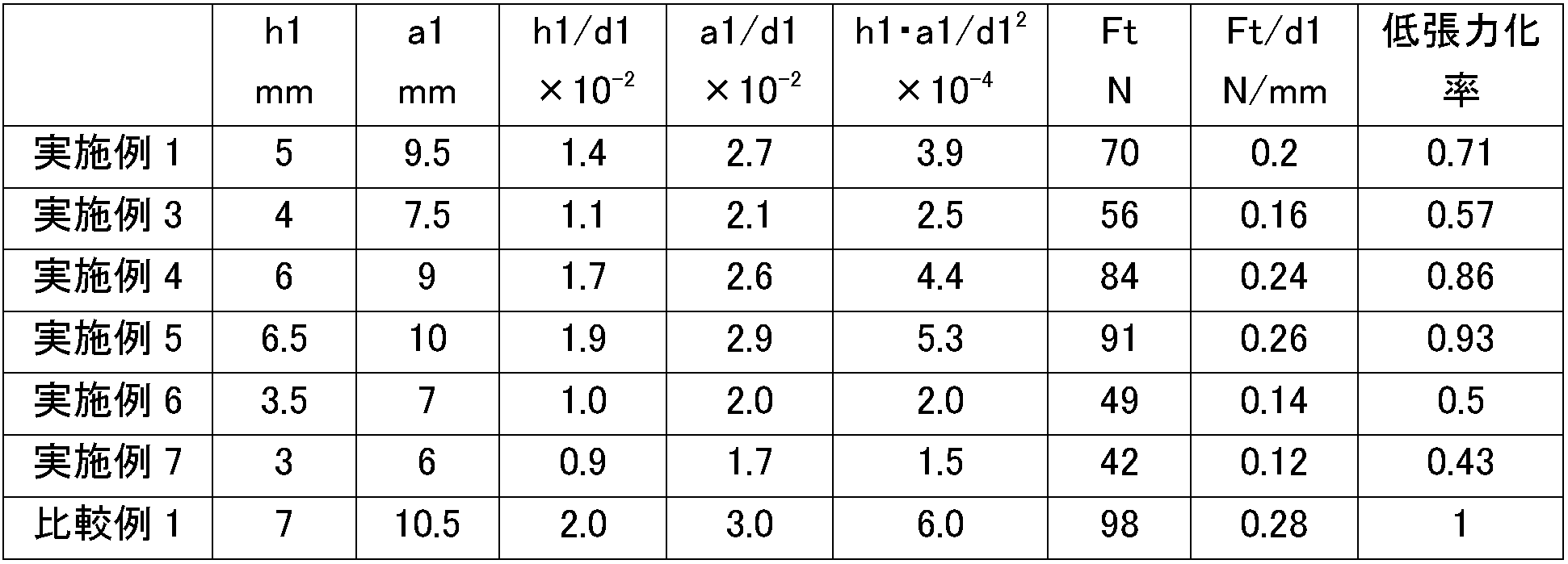
- Examples 3-7 From the second cylindrical material produced in Example 2 having an outer diameter of about 368 mm, an inner diameter of about 339 mm, and a width of about 120 mm, the nominal diameter (d1) is 350 mm, the ring width (h1) and the radial thickness.
- Eight pressure rings were produced for each example in the same manner as in Example 2 except that (a1) was set to the values shown in Table 1 and the tension Ft was adjusted so that the surface pressure was 0.08 MPa.
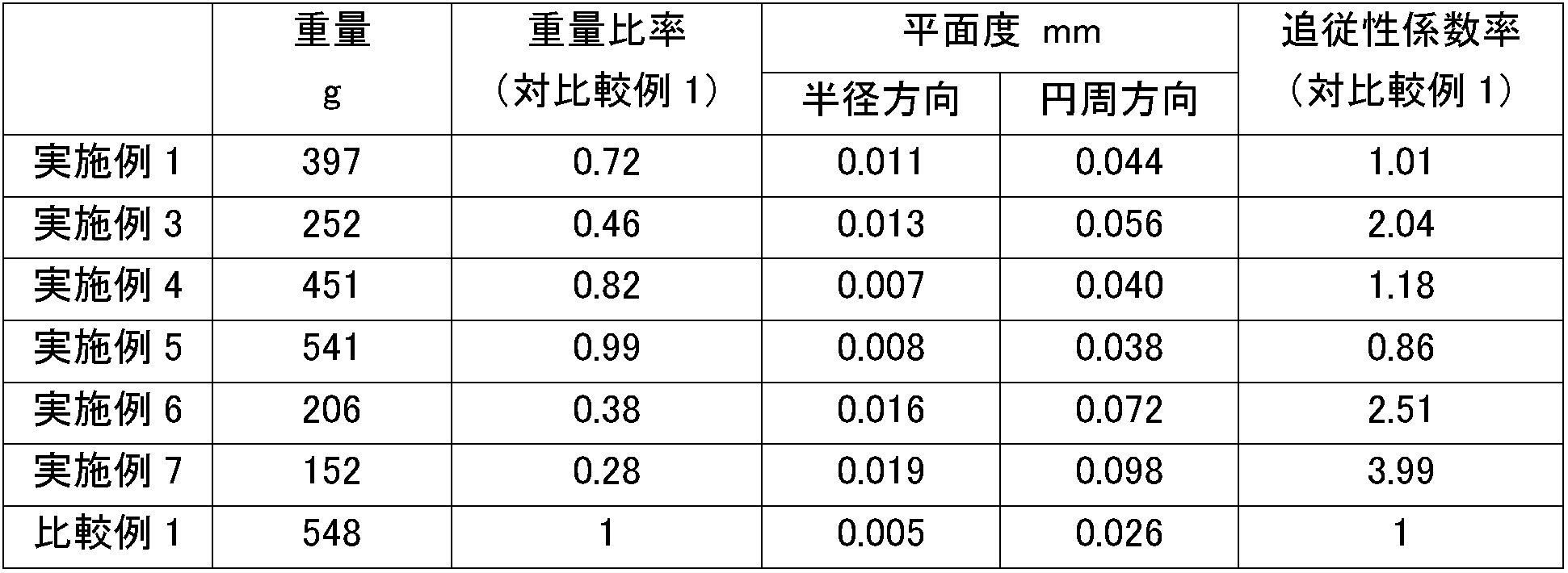
- Table 1 shows the dimensional relationship and tension Ft relationship, the measurement results of the weight and flatness measured in the same manner as in Example 1, the weight ratio and the followability coefficient ratio with respect to Comparative Example 1, and the results of Example 1 and Comparative Example 1. Are shown in Table 2.
- Example 5 the weight ratio is 0.46 to 0.82 and the tension reduction ratio is 0.57 to 0.86 compared to a conventional cast iron ring. It was confirmed that it can be processed to a ring accuracy of a level that does not cause any problems in use in a radial direction of 0.007 to 0.013 mm and a circumferential direction of 0.040 to 0.056 mm.
- Example 5 the steel material was used to reduce the cross-section from the cast iron ring of Comparative Example 1, but the weight ratio was due to the specific gravity difference (steel material specific gravity of 7.8 g / cm 3 and cast iron specific gravity of 7.0 g / cm 3 ).
- Example 8 Material composition is mass%, C: 0.36%, Si: 0.27%, Mn: 0.51%, P: 0.029%, S: 0.024%, Ni: 0.25%, Cr: 12.08%, outer diameter 110 mm, long A second cylindrical material having an outer diameter of about 353 mm, an inner diameter of about 311 mm, and a width of about 90 mm was produced from a steel bar having a thickness of 200 mm in the same manner as in Example 1.
- This second cylindrical material is annealed at 750 ° C for 21 hours after spheroidizing, and after removing the oxidized scale by shot blasting, the inner and outer circumferences are simultaneously roughened into a non-circular shape (cam shape) with a major axis of 352 mm and minor axis of 346 mm. After processing, parting was performed to obtain five non-circular rings.
- Thermal settling test The thermal settling test is based on JIS B 8037-5. This is done by first measuring the tension, closing the ring to the nominal diameter and heating at 300 ° C for 3 hours, then measuring the tension again and evaluating the rate of decline (in JIS, the degree of tangential tension decline). As a result of evaluating the five rings of Example 8, the average value of the thermal sag ratio was 3.6%, all were within 4%, and the variation was small.
- Example 9 Using a steel material having the same composition as in Example 8, a second cylindrical material having an outer diameter of about 348 mm, an inner diameter of about 319 mm, and a width of about 125 mm is produced by ring rolling, and the cylindrical material is heated again. Then, it was press-formed in a direction perpendicular to the axis to form a non-circular cylindrical material having a major axis of 351 mm and a minor axis of 345 mm. In this press molding, a lower mold and an upper mold having a predetermined elliptical shape were used. The obtained non-circular cylindrical material was spheroidized and annealed in the same manner as in Example 8.
- Example 8 After removing the oxidized scale by shot blasting, the inner and outer circumferences were simultaneously processed and parted off to form a non-circular ring. I got this book. As in Example 8, after quenching and tempering, finishing was performed, and nitriding and ion plating were further performed to obtain a pressure ring. Compared to Example 8, in Example 9, the machining time for the inner and outer peripheral simultaneous machining was shortened to about 1/5.
- Example 10 From the second cylindrical material produced in Example 8 with an outer diameter of about 353 mm, an inner diameter of about 311 mm, and a width of about 90 mm, the nominal diameter (d1) 330 mm, the ring width (h1) 6.0 mm, and the radial thickness (A1) An I-shaped oil ring body of 4.5 mm as shown in FIG. 8 was produced by turning. In the surface treatment, the entire oil ring main body was subjected to nitriding treatment.
- Example 11 The first cylindrical material having an outer diameter of about 180 mm and an inner diameter of about 50 mm, produced in the same manner as in Example 1, from the same steel bar having an outer diameter of 110 mm and a length of 200 mm used in Example 8 was used.
- the material for the ring body was prepared. A parting process, a heat treatment, a finishing process, a nitriding process, and the like were performed to produce an oil ring main body similar to that in Example 10. Compared to Example 10, in Example 11, the processing time could be significantly reduced.
- Example 12 Steel material with material composition of mass%, C: 0.86%, Si: 0.27%, Mn: 0.29%, P: 0.024%, S: 0.018%, Cr: 17.3%, Mo: 0.89%, V: 0.11%
- Five non-circular pressure rings were produced in the same manner as in Example 9 except that they were used.
- Example 13 Example 1 from a steel bar having a material composition of mass%, C: 0.48%, Si: 0.21%, Mn: 0.79%, Cr: 1.02%, V: 0.22%, an outer diameter of 110 mm and a length of 200 mm
- a second cylindrical material having an outer diameter of about 353 mm, an inner diameter of about 311 mm, and a width of about 90 mm was produced in the same manner as in Example 1, and after removing the oxidized scale by annealing and shot blasting, the long diameter was obtained.
- Example 2 Furthermore, in the same manner as in Example 1, after quenching and tempering, finishing was performed, and a rectangular shape having a nominal diameter (d1) of 330 mm, a ring width (h1) of 7 mm, and a radial thickness (a1) of 10 mm A pressure ring having a barrel-shaped, double-step abutment-shaped outer peripheral surface in cross section was formed, and a nitride layer by gas nitriding and a cermet sprayed coating by high-speed flame spraying were formed.
- d1 nominal diameter
- h1 ring width
- a1 radial thickness
- Example 8 Thermal sag rate Further, the thermal sag test performed in Example 8 was performed on the five rings of Example 13, and as a result, the average value of the thermal sag rate was 4.8%, all within 5%, and there was no variation. It was small.
- Example 14 A steel material having the same composition as in Example 13 was used and formed into a non-circular cylindrical material having a major axis of 351 mm and a minor axis of 345 mm in the same manner as in Example 9.
- the obtained non-circular cylindrical material was annealed in the same manner as in Example 13, and after removing the oxide scale by shot blasting, the inner and outer circumferences were simultaneously processed and parted off to obtain five non-circular rings. It was.
- After quenching and tempering, finishing was performed, and nitriding treatment and thermal spraying treatment were further performed to obtain a pressure ring.
- Example 14 compared to Example 13, the processing time for simultaneous inner and outer peripheral processing was shortened to about 1/5.
- Example 15 From the second cylindrical material having an outer diameter of about 353 mm, an inner diameter of about 311 mm, and a width of about 90 mm produced in Example 13, the nominal diameter (d1) 330 mm, the ring width (h1) 6.0 mm, and the radial thickness (A1) A 4.5 mm I-shaped oil ring body as shown in FIG. 8 was produced by turning. In the surface treatment, the entire oil ring main body was subjected to nitriding treatment.
- Example 16 A second cylindrical material having an outer diameter of about 300 mm and an inner diameter of about 280 mm is produced from a steel material having the same composition as that of Example 13 by ring rolling, and further, as in Example 11, an outer diameter of about 333 mm. An oil ring body material having an inner diameter of about 317 mm was produced, and an oil ring body similar to that of Example 15 was produced. Compared to Example 15, in Example 16, the machining time could be significantly reduced.
- Examples 17-20 Five non-circular pressure rings were produced for each steel material in the same manner as in Example 14 except that the steel materials shown in Table 3 were used. The results of the measurement of thermal conductivity and the thermal sag test in the same manner as in Example 13 are shown in Table 3 including the results of Example 13 and Comparative Example 1.
- Examples 13, 17 to 20 and Comparative Example 1 all contain P and S as inevitable impurities. * Cu of Example 20 is contained as an impurity. ** The unit of thermal conductivity is W / (m ⁇ K). *** The unit of heat sag rate is%.
- the thermal conductivity was 31 to 49 W / (m ⁇ K), and the thermal settling rate was 4.6 to 6.3%.
- the thermal conductivity is at least 30 / W / (m ⁇ K) of spheroidal graphite cast iron, 38 W / (m ⁇ K), and further 49 / W / (m ⁇ K), CV graphite cast iron and flake graphite cast iron A value corresponding to is also obtained.
- the heat set rate is at least less than 7%, and values of less than 6% and even less than 5% are also obtained.
Landscapes
- Chemical & Material Sciences (AREA)
- Engineering & Computer Science (AREA)
- Mechanical Engineering (AREA)
- Materials Engineering (AREA)
- Metallurgy (AREA)
- Organic Chemistry (AREA)
- General Engineering & Computer Science (AREA)
- Crystallography & Structural Chemistry (AREA)
- Physics & Mathematics (AREA)
- Thermal Sciences (AREA)
- Pistons, Piston Rings, And Cylinders (AREA)
Abstract
Description
1×10⁻² < h1/d1 < 1.8×10⁻²
の関係を満たすことが好ましく、径方向厚さ(a1)と前記呼び径(d1)が
2×10⁻²< a1/d1 < 2.8×10⁻²
の関係を満たすことが好ましく、さらに、前記リング幅(h1)と前記径方向厚さ(a1)と前記呼び径(d1)が
2×10⁻⁴< (h1×a1)/(d1)2 < 5×10⁻⁴
の関係を満たすことが好ましい。
K = 3・Ft・d12/(E・h1・a13)
ここで、Ftはリング張力、d1は呼び径、Eはヤング率、h1はリング幅寸法、a1は径方向厚さ寸法である。この式から、リングの追従性は、リング本体の寸法、特に径方向厚さ寸法a1の3乗に反比例するため、径方向厚さ寸法a1をできるだけ小さくすることが好ましく、結果的に図8に示すような形状(「I型形状」ともいう。)を取ることが好ましい。よって、本発明のピストンリングの製造方法では、図7(a)、図7(b)、及び図8に示すオイルリングにできるだけ近い素材形状とするため、第2の円筒状素材が少なくとも外周面に軸方向に一定間隔で形成された複数の凹部を有するように、異形形状の主ロールを使用することが好ましい。図9に示す第2の円筒状素材は、外周面及び内周面の両方に軸方向に一定間隔で形成された複数の凹部を有しており、その場合は異形形状の主ロールとマンドレルを使用することが好ましい。
SUS420J2材の外径110 mm、長さ200 mmの棒鋼を、1000℃に加熱し、外径165 mm、高さ約90 mmの円板状成形体にプレス成形し、さらに、コアポンチにより中央部に凹部を形成し、それを貫通、穴開けして、外径約180 mm、内径約50 mmの第1の円筒状素材を作製した。次に、第1の円筒状素材を高周波誘導加熱装置により再度加熱し、リングローリングミルにセットし、リングローリング加工により外径約364 mm、内径約332 mm、幅約110 mmの第2の円筒状素材を作製した。この第2の円筒状素材を790℃、10時間の焼鈍後、ショットブラストによる酸化スケールの除去後、長径362 mm、短径356 mmの非円形形状(楕円形状等)に内外周を同時に粗加工した後、突切加工して非円形形状のリングを8本得た。900℃からの焼入、490℃、3時間の焼戻しの後、仕上加工を施して、呼び径(d1)350 mm、リング幅(h1)5 mm、径方向厚さ(a1)9.5 mmの矩形断面で外周面がバレル形状、ダブルステップ合口形状の圧力リングとした。次に、460℃、5時間のガス窒化によりリング全面に窒化層を約70μm形成し、さらに外周には、高速フレーム溶射によりNi合金基地中に微細なCr炭化物粒子が分散した複合材粒子を主たる構成粒子(スルザーメテコ社のSM5241粉末)とするサーメット溶射被膜を約500μm形成し、最終的には溶射被膜の膜厚約350μmまで仕上研磨を施した。ここで、ガス窒化により表面に生成した化合物層(白層)は研削除去した。なお、面圧が0.08 MPaとなるように張力Ftは70 Nに調整した。
実施例1の圧力リングの重量は、電子天秤にて測定した8本の重量の平均値とした。平均値は397 gであった。
実施例1のリングを定盤上に置き、合口部2点、合口から90°、180°及び270°の各点の5点に5Nの荷重を加え、半径方向と円周方向の平面度を測定した。平面度は基準面に平行な面からのリング側面の自然に発生する偏差と定義され(JIS B 8037-2)、リングのねじれや皿状態を評価するのに用いられる。半径方向の平面度は、半径が1.5±0.05 mmの球面形測定子を用いて約1 Nの測定荷重で、リングの上側面において、荷重点の中央で測定する4点の測定値の最大値とし、円周方向の平面度は、リングの厚さの中心で、かつ荷重点の中央で測定し、振れの最大値と最小値の差とする。実施例1の半径方向の平面度は0.011 mm、円周方向の平面度は0.044 mmであった。
材料組成が、質量%で、C:3.8%、Si:2.6%、Mn:0.5%、P:0.04%、S:0.01%、Cr:0.09%、Ni:0.88%、V:0.06%、Cu:2.42%の鋳鉄から、溶解、鋳造して第2の円筒状素材に該当するCV黒鉛鋳鉄製素材を作製し、窒化処理及び溶射処理を省略した以外は、実施例1と同様にして、呼び径(d1)350 mm、リング幅(h1)7 mm、径方向厚さ(a1)10.5 mmの矩形断面で外周面がバレル形状、ダブルステップ合口形状の圧力リングを作製した。比較例1のリングの重量は611 gであった。比較例1においても、面圧が0.08 MPaとなるように張力Ftは98Nに調整した。実施例1と同様にして平面度の測定を行った結果、半径方向の平面度は0.005 mm、円周方向の平面度は0.026 mmであった。実施例1と比較すると、素材が鋳鉄であるため、平面度は約40~55%小さかったが、実施例1では、比較例1に対し、約35%軽量化されていることが分かる。
実施例1と同じ組成の鋼材を用い、リングローリング加工により外径約368 mm、内径約339 mm、幅約120 mmの第2の円筒状素材を作製し、さらに、その円筒状素材を再度加熱し、軸に直角な方向にプレス成形して、長軸370 mm、短軸364 mmの非円形形状の円筒状素材に成形した。なお、このプレス成形では、所定の楕円形状をした下型及び上型を使用した。得られた非円形形状の円筒状素材は、実施例1と同様にして、焼鈍し、ショットブラストによる酸化スケールの除去後、内外周同時加工、突切加工して非円形形状のリングを8本得た。実施例1と同様に、焼入、焼戻しの後、仕上加工を行い、さらに窒化処理と溶射処理を施して、圧力リングとした。実施例2では、実施例1に比べ内外周同時加工の加工時間が約1/5に短縮された。
実施例2で作製した、外径約368 mm、内径約339 mm、幅約120 mmの第2の円筒状素材から、呼び径(d1)を350 mm、リング幅(h1)と径方向厚さ(a1)を表1に示す数値とし、面圧が0.08 MPaとなるように張力Ftを調整した以外は、実施例2と同様にして、各実施例につき8本の圧力リングを作製した。寸法関係及び張力Ft関係を表1に、実施例1と同様に測定した重量及び平面度の測定結果、並びに比較例1に対する重量比率及び追従性係数率を、実施例1及び比較例1の結果も含め表2に示す。ここで、追従性係数率(対比較例1)は、実施例1の鋼材のヤング率(E)を215 GPa、比較例1の鋳鉄のヤング率(E)を160 GPaとし、K = 3Ftd12/Eh1a13により計算した。
材料組成が、質量%で、C:0.36%、Si:0.27%、Mn:0.51%、P:0.029%、S:0.024%、Ni:0.25%、Cr:12.08%で、外径110 mm、長さ200 mmの棒鋼から、実施例1と同様にして、外径約353 mm、内径約311 mm、幅約90 mmの第2の円筒状素材を作製した。この第2の円筒状素材を750℃、21時間の球状化焼鈍後、ショットブラストによる酸化スケールの除去後、長径352 mm、短径346 mmの非円形形状(カム形状)に内外周を同時に粗加工した後、突切加工して非円形形状のリングを5本得た。1000℃からの焼入、600℃、3時間の焼戻しの後、仕上加工を施して、呼び径(d1)330 mm、リング幅(h1)7 mm、径方向厚さ(a1)10 mmの矩形断面で外周面がバレル形状、ダブルステップ合口形状の圧力リングとした。次に、570℃、4時間のガス窒化によりリング全面に窒化層を約100μm形成し、さらに外周には、アークイオンプレーティングによりCrN層を約50μm形成した。ここで、ガス窒化により表面に生成した化合物層(白層)は研削除去した。
熱ヘタリ試験は、JIS B 8037-5に基づく。最初に張力を測定し、呼び径にリングを閉じて300℃で3時間加熱した後、再度張力を測定して、その減退率(JISでは接線方向張力減退度)を評価することによって行われる。実施例8の5本のリングについて評価した結果、熱ヘタリ率の平均値は3.6%であり、いずれも4%以内で、バラツキも小さかった。
材料組成が、質量%で、C:3.8%、Si:2.6%、Mn:0.5%、P:0.16%、S:0.01%、Mo:0.72%、Cu:0.68%の鋳鉄から、溶解、鋳造して第2の円筒状素材に該当する鋳鉄製素材を作製し、窒化処理及びイオンプレーティング処理を省略した以外は、実施例8と同様にして、圧力リングを作製した。実施例8と同様にして熱ヘタリ試験を行った結果、熱ヘタリ率の平均値は7.2%であり、実施例8と比較すると、実施例8の耐熱ヘタリ性が著しく向上したことがわかる。
実施例8と同じ組成の鋼材を用い、リングローリング加工により外径約348 mm、内径約319 mm、幅約125 mmの第2の円筒状素材を作製し、さらに、その円筒状素材を再度加熱し、軸に直角な方向にプレス成形して、長軸351 mm、短軸345 mmの非円形形状の円筒状素材に成形した。なお、このプレス成形では、所定の楕円形状をした下型及び上型を使用した。得られた非円形形状の円筒状素材は、実施例8と同様にして、球状化焼鈍し、ショットブラストによる酸化スケールの除去後、内外周同時加工、突切加工して非円形形状のリングを5本得た。実施例8と同様に、焼入、焼戻しの後、仕上加工を行い、さらに窒化処理とイオンプレーティング処理を施して、圧力リングとした。実施例8に比べ、実施例9では内外周同時加工の加工時間が約1/5に短縮された。
実施例8で作製した、外径約353 mm、内径約311 mm、幅約90 mmの第2の円筒状素材から、呼び径(d1)330 mm、リング幅(h1)6.0 mm、径方向厚さ(a1)4.5 mmの図8に示すようなI型形状のオイルリング本体を旋削加工により作製した。表面処理は、オイルリング本体全体に窒化処理を施した。
実施例8で使用したのと同じ外径110 mm、長さ200 mmの棒鋼から、実施例1と同様にして作製した外径約180 mm、内径約50 mmの第1の円筒状素材を経て、リングローリング加工により外径約300 mm、内径約280 mmの第2の円筒状素材を作製した。さらに、図9に示すような断面の第2の円筒状素材が成形できるような形状をもつ主ロール及びマンドレルを使用してリングローリング加工を行い、外径約333 mm、内径約317 mmのオイルリング本体の素材を作製した。突切加工、熱処理、仕上加工、窒化処理等を行い、実施例10と同様なオイルリング本体を作製した。実施例10に比べ、実施例11では加工時間を大幅に低減することができた。
材料組成が、質量%で、C:0.86%、Si:0.27%、Mn:0.29%、P:0.024%、S:0.018%、Cr:17.3%、Mo:0.89%、V:0.11%の鋼材を使用した以外は、実施例9と同様にして、非円形形状の圧力リングを5本作製した。実施例8と同様にして熱ヘタリ試験を行った結果、熱ヘタリ率の平均値は2.9%であり、実施例8以上の耐熱ヘタリ性を有していたことがわかる。
材料組成が、質量%で、C:0.48%、Si:0.21%、Mn:0.79%、Cr:1.02%、V:0.22%で、外径110 mm、長さ200 mmの棒鋼から、実施例1と同様にして、外径約353 mm、内径約311 mm、幅約90 mmの第2の円筒状素材を作製し、実施例1と同様にして焼鈍、ショットブラストによる酸化スケールの除去後、長径352 mm、短径346 mmの非円形形状(カム形状)に内外周を同時に粗加工した後、突切加工して非円形形状のリングを5本得た。さらに、実施例1と同様にして、焼入、焼戻しの後、仕上加工を施して、呼び径(d1)330 mm、リング幅(h1)7 mm、径方向厚さ(a1)10 mmの矩形断面で外周面がバレル形状、ダブルステップ合口形状の圧力リングとし、ガス窒化による窒化層と、高速フレーム溶射によるサーメット溶射被膜を形成した。
熱伝導率は、実施例13のリングから測定用サンプルを切り出し、研磨して、レーザーフラッシュ法により3回測定した。3回の測定値の平均値は38 W/(m・K)であり、CV黒鉛鋳鉄の熱伝導率に匹敵する値であった。
また、実施例8で行った熱ヘタリ試験を、実施例13の5本のリングについて行った結果、熱ヘタリ率の平均値は4.8%であり、いずれも5%以内で、バラツキも小さかった。
比較例1の材料組成の鋳鉄から、実施例13と同じ第2の円筒状素材に該当するCV黒鉛鋳鉄製素材を作製し、窒化処理及び溶射処理を省略した以外は、実施例13と同様にして、圧力リングを作製した。実施例13と同様にして熱伝導率の測定と熱ヘタリ試験を行った結果、熱伝導率の平均値は36 W/(m・K)、熱ヘタリ率の平均値は7.0%であり、実施例13と比較すると、実施例13の耐熱ヘタリ性が著しく向上したことがわかる。
実施例13と同じ組成の鋼材を用い、実施例9と同様にして、長軸351 mm、短軸345 mmの非円形形状の円筒状素材に成形した。得られた非円形形状の円筒状素材は、実施例13と同様にして、焼鈍し、ショットブラストによる酸化スケールの除去後、内外周同時加工、突切加工して非円形形状のリングを5本得た。実施例13と同様に、焼入、焼戻しの後、仕上加工を行い、さらに窒化処理と溶射処理を施して、圧力リングとした。実施例14では、実施例13に比べ内外周同時加工の加工時間が約1/5に短縮された。
実施例13で作製した外径約353 mm、内径約311 mm、幅約90 mmの第2の円筒状素材から、呼び径(d1)330 mm、リング幅(h1)6.0 mm、径方向厚さ(a1)4.5 mmの図8に示すようなI型形状のオイルリング本体を旋削加工により作製した。表面処理は、オイルリング本体全体に窒化処理を施した。
実施例13と同じ組成の鋼材から、リングローリング加工により外径約300 mm、内径約280 mmの第2の円筒状素材を作製し、さらに、実施例11と同様にして、外径約333 mm、内径約317 mmのオイルリング本体の素材を作製し、実施例15と同様なオイルリング本体を作製した。実施例15に比べ、実施例16では加工時間を大幅に低減することができた。
材料組成が、表3に示す鋼材を使用した以外は、実施例14と同様にして非円形形状の圧力リングを各鋼材につき5本ずつ作製した。実施例13と同様にして、熱伝導率の測定と熱ヘタリ試験を行った結果について、実施例13及び比較例1の結果も含め表3に示す。

* 実施例20のCuは不純物として含まれたものである。
** 熱伝導率の単位はW/(m・K)である。
*** 熱ヘタリ率の単位は%である。
Claims (19)
- 呼び径(d1)が200 mm以上1100 mm未満のピストンリングであって、前記ピストンリングが熱間鍛造した円筒状鋼素材から製造されることを特徴とするピストンリング。
- 請求項1に記載のピストンリングにおいて、リング幅(h1)と前記呼び径(d1)が
1×10⁻² < h1/d1 < 1.8×10⁻²
の関係を満たすことを特徴とするピストンリング。 - 請求項1又は2に記載のピストンリングにおいて、径方向厚さ(a1)と前記呼び径(d1)が
2×10⁻² < a1/d1 < 2.8×10⁻²
の関係を満たすことを特徴とするピストンリング。 - 請求項1~3のいずれかに記載のピストンリングにおいて、前記リング幅(h1)と前記径方向厚さ(a1)と前記呼び径(d1)が
2×10⁻⁴ < (h1×a1)/(d1)2 < 5×10⁻⁴
の関係を満たすことを特徴とするピストンリング。 - 請求項1~4のいずれかに記載のピストンリングにおいて、前記ピストンリングの張力(Ft)の前記呼び径(d1)に対する比(Ft/d1)が0.1~0.25 N/mmであることを特徴とするピストンリング。
- 請求項1~5のいずれかに記載のピストンリングにおいて、前記母材が、炭素鋼、低合金鋼、バネ鋼、軸受鋼、マルテンサイト系ステンレス鋼から選択された鋼であることを特徴とするピストンリング。
- 請求項6に記載のピストンリングにおいて、前記母材が、質量%で、C:0.2~1.0%、Si:0.1~1.0%、Mn:0.1~1.0%、Cr:10~20%、Ni:0~0.6%、Mo:0~1.5%、V:0~0.15%、残部Fe及び不可避的不純物からなる組成を有することを特徴とするピストンリング。
- 請求項7に記載のピストンリングにおいて、前記母材が焼戻しマルテンサイト中にクロム炭化物を分散した組織を有し、熱ヘタリ率が4%以下であることを特徴とするピストンリング。
- 請求項6に記載のピストンリングにおいて、前記母材が、質量%で、C:0.45~1.10%、Si:0.15~1.60%、Mn:0.30~1.15%、Cr:0.50~1.60%、V:0~0.25%、Mo:0~0.35%、B:0~0.005%、残部Fe及び不可避的不純物からなる組成を有することを特徴とするピストンリング。
- 請求項9に記載のピストンリングにおいて、前記母材の熱伝導率が30 W/(m・K)以上であることを特徴とするピストンリング。
- 請求項9又は10に記載のピストンリングにおいて、前記母材が焼戻しマルテンサイト中に炭化物を分散した組織を有し、熱ヘタリ率が8%以下であることを特徴とするピストンリング。
- 請求項1~11のいずれかに記載のピストンリングにおいて、前記ピストンリングの外周摺動面に、窒化皮膜、めっき皮膜、溶射皮膜、化成処理皮膜、及びイオンプレーティング皮膜からなるグループから選択された1又は2以上の皮膜を有していることを特徴とするピストンリング。
- 請求項1~12のいずれかに記載のピストンリングにおいて、前記ピストンリングの側面に窒化皮膜、めっき皮膜、及び化成処理皮膜からなるグループから選択された1又は2以上の皮膜を有していることを特徴とするピストンリング。
- 呼び径(d1)が200 mm以上1100 mm未満のピストンリング用の円筒状鋼素材であって、前記円筒状鋼素材が周方向にファイバーフロー組織を有することを特徴とするピストンリング用素材。
- 請求項14に記載のピストンリング用素材において、圧力リング用に、前記円筒状鋼素材の軸に垂直な断面が非円形形状であることを特徴とするピストンリング用素材。
- 請求項14に記載のピストンリング用素材において、オイルリング用に、前記円筒状鋼素材の少なくとも外周面が軸方向に一定間隔で形成された複数の凹部を有していることを特徴とするピストンリング用素材。
- 呼び径(d1)が200 mm以上1100 mm未満のピストンリングの製造方法であって、所定の長さに切断された円柱状鋼素材を加熱し、プレス成形によって円板状成形体に据込み加工する第1の熱間鍛造工程と、前記円板状成形体からコアポンチにより中央部に凹部を形成し穴開け加工して第1の円筒状素材に加工する第2の熱間鍛造工程と、前記第1の円筒状素材からリングローリングミルにより拡径した第2の円筒状素材に加工する第3の熱間鍛造工程と、前記第2の円筒状素材からピストンリングに加工する機械加工工程を含むことを特徴とするピストンリングの製造方法。
- 請求項17に記載のピストンリングの製造方法において、前記第2の円筒状素材が軸に直角な断面で非円形形状を有するように、前記第3の熱間鍛造工程の後に、前記第2の円筒状素材を軸に直角な方向にプレス成形することを特徴とするピストンリングの製造方法。
- 請求項17に記載のピストンリングの製造方法において、前記第2の円筒状素材が少なくとも外周面に軸方向に一定間隔で形成された複数の凹部を有するように、前記第3の熱間鍛造工程において、異形形状の主ロールを使用することを特徴とするピストンリングの製造方法。
Priority Applications (3)
| Application Number | Priority Date | Filing Date | Title |
|---|---|---|---|
| CN201480030692.2A CN105283697B (zh) | 2013-06-07 | 2014-06-05 | 活塞环及其原料以及它们的制造方法 |
| EP14807123.6A EP3006787A4 (en) | 2013-06-07 | 2014-06-05 | Piston ring, raw material therefor, and production method for both |
| KR1020167000225A KR20160029793A (ko) | 2013-06-07 | 2014-06-05 | 피스톤 링 및 그 소재 및 그 제조 방법 |
Applications Claiming Priority (6)
| Application Number | Priority Date | Filing Date | Title |
|---|---|---|---|
| JP2013120497A JP6312988B2 (ja) | 2013-06-07 | 2013-06-07 | 大型ピストンリングの製造方法、大型ピストンリング素材、及び大型ピストンリング。 |
| JP2013-120497 | 2013-06-07 | ||
| JP2013252020A JP2015108417A (ja) | 2013-12-05 | 2013-12-05 | 大型ピストンリング及びその素材並びにそれらの製造方法。 |
| JP2013-252020 | 2013-12-05 | ||
| JP2014-043753 | 2014-03-06 | ||
| JP2014043753A JP6475416B2 (ja) | 2014-03-06 | 2014-03-06 | ピストンリング及びその製造方法 |
Publications (1)
| Publication Number | Publication Date |
|---|---|
| WO2014196614A1 true WO2014196614A1 (ja) | 2014-12-11 |
Family
ID=52008245
Family Applications (1)
| Application Number | Title | Priority Date | Filing Date |
|---|---|---|---|
| PCT/JP2014/065010 Ceased WO2014196614A1 (ja) | 2013-06-07 | 2014-06-05 | ピストンリング及びその素材並びにそれらの製造方法 |
Country Status (4)
| Country | Link |
|---|---|
| EP (1) | EP3006787A4 (ja) |
| KR (1) | KR20160029793A (ja) |
| CN (4) | CN107262641A (ja) |
| WO (1) | WO2014196614A1 (ja) |
Cited By (4)
| Publication number | Priority date | Publication date | Assignee | Title |
|---|---|---|---|---|
| CN104805273A (zh) * | 2015-04-01 | 2015-07-29 | 安国清 | 一种气钉枪腔体活塞环硬度的处理方法 |
| JP2021060048A (ja) * | 2019-10-03 | 2021-04-15 | 日本ピストンリング株式会社 | 内燃機関の摺動構造、内燃機関の摺動構造の作り込み方法 |
| CN114164332A (zh) * | 2021-11-26 | 2022-03-11 | 湖南华菱湘潭钢铁有限公司 | 一种耐高温磨损耐磨钢板的生产方法 |
| CN120190302A (zh) * | 2025-04-16 | 2025-06-24 | 陕西天尧钛金属有限公司 | 一种马氏体环件生产方法 |
Families Citing this family (15)
| Publication number | Priority date | Publication date | Assignee | Title |
|---|---|---|---|---|
| JP6313601B2 (ja) * | 2014-01-23 | 2018-04-18 | 株式会社リケン | ピストンリング及びその製造方法 |
| CN105921651A (zh) * | 2016-06-28 | 2016-09-07 | 中国南方航空工业(集团)有限公司 | 一种高温合金高筒薄壁环形件的辗制方法 |
| CN106947922A (zh) * | 2017-03-13 | 2017-07-14 | 浙江工贸职业技术学院 | 一种马氏体钢及其结构硬化处理方法 |
| US10563764B2 (en) * | 2017-05-26 | 2020-02-18 | Mahle International Gmbh | Coated steel piston ring |
| CN107420309B (zh) * | 2017-08-30 | 2023-05-12 | 广东美芝制冷设备有限公司 | 旋转压缩机用活塞及其制备方法 |
| CN107717341A (zh) * | 2017-09-15 | 2018-02-23 | 中国原子能科学研究院 | 模块式金属构筑成形方法 |
| CN107626880B (zh) * | 2017-09-15 | 2020-10-09 | 中国原子能科学研究院 | 一种大型环形锻件的制造工艺 |
| CN108149133B (zh) * | 2017-12-08 | 2020-12-18 | 安泰科技股份有限公司 | 一种加硼高碳、微合金化的高强度碳素纯净钢及制备方法 |
| CN108608209A (zh) * | 2018-03-30 | 2018-10-02 | 温州市华海密封件有限公司 | 整体式金属环形制品的加工方法 |
| US11512777B2 (en) * | 2018-04-26 | 2022-11-29 | Kabushiki Kaisha Riken | Piston ring |
| CN109433885B (zh) * | 2018-09-07 | 2020-11-10 | 马继荃 | 煅压冲淬一体成型工艺及设备装置 |
| JP7121929B2 (ja) | 2019-12-25 | 2022-08-19 | 日立金属株式会社 | リング圧延材の製造方法 |
| CN111334702A (zh) * | 2020-03-20 | 2020-06-26 | 浙江天马轴承集团有限公司 | 一种高强高氮稀土不锈轴承钢的制备方法 |
| JP7292322B2 (ja) * | 2021-04-12 | 2023-06-16 | トクセン工業株式会社 | オイルリング用線 |
| CN114381667A (zh) * | 2021-12-24 | 2022-04-22 | 鞍钢集团矿业有限公司 | 一种高韧性高铬高碳铸钢及其热处理方法 |
Citations (5)
| Publication number | Priority date | Publication date | Assignee | Title |
|---|---|---|---|---|
| JPH02217667A (ja) * | 1989-02-17 | 1990-08-30 | Honda Motor Co Ltd | 内燃機関用繊維強化ピストンリング |
| JPH06221436A (ja) | 1993-01-25 | 1994-08-09 | Riken Corp | 鋳鋼製ピストンリング材 |
| JP2002348639A (ja) * | 2001-05-21 | 2002-12-04 | Aichi Steel Works Ltd | イオンプレーティング処理に適した疲労強度,耐熱へたり性に優れたピストンリング用鋼 |
| JP2003254157A (ja) * | 2002-03-05 | 2003-09-10 | Nippon Piston Ring Co Ltd | ピストンリング |
| JP2005314744A (ja) * | 2004-04-28 | 2005-11-10 | Nippon Koshuha Steel Co Ltd | ピストンリング用材料及びその材料を用いたピストンリング |
Family Cites Families (29)
| Publication number | Priority date | Publication date | Assignee | Title |
|---|---|---|---|---|
| GB174851A (en) * | 1921-01-07 | 1922-02-09 | Percy Porter Hinckley | Improvements in and relating to piston rings |
| GB316802A (en) * | 1928-09-15 | 1929-08-08 | William Arthur Oubridge | Piston packing rings |
| GB328671A (en) * | 1929-01-28 | 1930-04-28 | Josue Vanderperren | Improvements in or relating to piston rings |
| US3586544A (en) * | 1966-07-20 | 1971-06-22 | Mecanique De Pringy Soc D | Method of producing piston rings |
| SU1209348A1 (ru) * | 1983-06-10 | 1986-02-07 | Нижнеднепровский Ордена Октябрьской Революции Трубопрокатный Завод Им.Г.Либкнехта | Способ изготовлени кольцевых изделий |
| JPS6313639A (ja) * | 1986-07-05 | 1988-01-20 | Sanden Corp | ピストンリングの加工方法 |
| CN87213091U (zh) * | 1987-08-30 | 1988-10-19 | 海陵内燃机配件总厂 | 椭圆筒体活塞环仿形车割机床 |
| JPH06145912A (ja) * | 1992-11-13 | 1994-05-27 | Hitachi Metals Ltd | ピストンリング材 |
| CN2160763Y (zh) * | 1993-06-23 | 1994-04-06 | 谭军 | 组合式活塞环 |
| JPH10252890A (ja) * | 1997-03-13 | 1998-09-22 | Kanai Hiroaki | オイルリング |
| CN1085784C (zh) * | 1998-08-10 | 2002-05-29 | 日野自动车工业株式会社 | 发动机的活塞 |
| CN2371395Y (zh) * | 1998-11-18 | 2000-03-29 | 高东阳 | 活塞环 |
| EP1063454B1 (en) * | 1999-06-25 | 2006-04-19 | Hitachi Metals, Ltd. | Self-lubricating piston ring material for internal combustion engine and piston ring |
| JP4680380B2 (ja) * | 2000-12-26 | 2011-05-11 | 株式会社リケン | ピストンリング及びその製造方法 |
| JP2003113940A (ja) * | 2001-08-02 | 2003-04-18 | Riken Corp | スチール製ピストンリング |
| CN2578536Y (zh) * | 2002-09-19 | 2003-10-08 | 伊贤华 | 一种摩托车用活塞油环 |
| UA64642C2 (en) * | 2003-09-08 | 2005-07-15 | Public Corp Odesa Piston Ring | Piston ring |
| RU2279328C2 (ru) * | 2004-03-09 | 2006-07-10 | Общество с ограниченной ответственностью "ОМЗ-Спецсталь" | Способ ковки крупногабаритных колец |
| JP4307329B2 (ja) * | 2004-05-31 | 2009-08-05 | 大同特殊鋼株式会社 | ピストンリング用線材及びピストンリング |
| JP2006144700A (ja) * | 2004-11-22 | 2006-06-08 | Toyota Motor Corp | 内燃機関用エンジンのピストン及び内燃機関用エンジンのピストンとピストンリングの組合せ |
| JP2007064346A (ja) * | 2005-08-31 | 2007-03-15 | Nippon Piston Ring Co Ltd | 圧力リング及びその製造方法 |
| JP4633639B2 (ja) * | 2006-01-31 | 2011-02-16 | 日本ピストンリング株式会社 | 3ピースオイルリング及び3ピースオイルリングとピストンとの組合せ |
| JP2009091927A (ja) * | 2007-10-05 | 2009-04-30 | Mitsubishi Heavy Ind Ltd | 往復動機関のピストンリング |
| CN101649790B (zh) * | 2009-07-20 | 2011-09-07 | 南京飞燕活塞环股份有限公司 | 一种钢制活塞气环的加工方法 |
| JP2012062983A (ja) * | 2010-09-17 | 2012-03-29 | Tpr Co Ltd | ピストンリング |
| DE102011085476A1 (de) * | 2011-10-28 | 2013-05-02 | Ks Kolbenschmidt Gmbh | Funktionsoptimierte Gestaltung einer Zylinderlaufbuchse |
| CN102513511B (zh) * | 2011-12-29 | 2013-08-28 | 南京飞燕活塞环股份有限公司 | 偏浇道活塞环造型装置 |
| CN102615224B (zh) * | 2012-03-30 | 2015-12-02 | 山东建筑大学 | 内台阶截面环件径轴向轧制成形的方法 |
| CN204018370U (zh) * | 2013-12-24 | 2014-12-17 | 温州一川金属科技有限公司 | 活塞环专用轧辊组 |
-
2014
- 2014-06-05 KR KR1020167000225A patent/KR20160029793A/ko not_active Ceased
- 2014-06-05 WO PCT/JP2014/065010 patent/WO2014196614A1/ja not_active Ceased
- 2014-06-05 CN CN201710243543.XA patent/CN107262641A/zh active Pending
- 2014-06-05 CN CN201480030692.2A patent/CN105283697B/zh active Active
- 2014-06-05 CN CN201710243544.4A patent/CN107255053B/zh active Active
- 2014-06-05 CN CN201710243454.5A patent/CN107269836A/zh active Pending
- 2014-06-05 EP EP14807123.6A patent/EP3006787A4/en not_active Withdrawn
Patent Citations (5)
| Publication number | Priority date | Publication date | Assignee | Title |
|---|---|---|---|---|
| JPH02217667A (ja) * | 1989-02-17 | 1990-08-30 | Honda Motor Co Ltd | 内燃機関用繊維強化ピストンリング |
| JPH06221436A (ja) | 1993-01-25 | 1994-08-09 | Riken Corp | 鋳鋼製ピストンリング材 |
| JP2002348639A (ja) * | 2001-05-21 | 2002-12-04 | Aichi Steel Works Ltd | イオンプレーティング処理に適した疲労強度,耐熱へたり性に優れたピストンリング用鋼 |
| JP2003254157A (ja) * | 2002-03-05 | 2003-09-10 | Nippon Piston Ring Co Ltd | ピストンリング |
| JP2005314744A (ja) * | 2004-04-28 | 2005-11-10 | Nippon Koshuha Steel Co Ltd | ピストンリング用材料及びその材料を用いたピストンリング |
Non-Patent Citations (2)
| Title |
|---|
| MINEDA ET AL., SOKEIZAI, vol. 50, no. 12, 2009, pages 48 - 51 |
| See also references of EP3006787A4 * |
Cited By (5)
| Publication number | Priority date | Publication date | Assignee | Title |
|---|---|---|---|---|
| CN104805273A (zh) * | 2015-04-01 | 2015-07-29 | 安国清 | 一种气钉枪腔体活塞环硬度的处理方法 |
| JP2021060048A (ja) * | 2019-10-03 | 2021-04-15 | 日本ピストンリング株式会社 | 内燃機関の摺動構造、内燃機関の摺動構造の作り込み方法 |
| CN114164332A (zh) * | 2021-11-26 | 2022-03-11 | 湖南华菱湘潭钢铁有限公司 | 一种耐高温磨损耐磨钢板的生产方法 |
| CN114164332B (zh) * | 2021-11-26 | 2023-10-24 | 湖南华菱湘潭钢铁有限公司 | 一种耐高温磨损耐磨钢板的生产方法 |
| CN120190302A (zh) * | 2025-04-16 | 2025-06-24 | 陕西天尧钛金属有限公司 | 一种马氏体环件生产方法 |
Also Published As
| Publication number | Publication date |
|---|---|
| EP3006787A1 (en) | 2016-04-13 |
| KR20160029793A (ko) | 2016-03-15 |
| CN107262641A (zh) | 2017-10-20 |
| CN105283697B (zh) | 2018-02-23 |
| CN107255053A (zh) | 2017-10-17 |
| CN107255053B (zh) | 2019-11-05 |
| EP3006787A4 (en) | 2017-07-19 |
| CN105283697A (zh) | 2016-01-27 |
| CN107269836A (zh) | 2017-10-20 |
Similar Documents
| Publication | Publication Date | Title |
|---|---|---|
| WO2014196614A1 (ja) | ピストンリング及びその素材並びにそれらの製造方法 | |
| JP6312988B2 (ja) | 大型ピストンリングの製造方法、大型ピストンリング素材、及び大型ピストンリング。 | |
| CN102174936B (zh) | 旋转式压缩机用滑块及其制备方法 | |
| JP2014237152A5 (ja) | ||
| EP2578909B1 (en) | Pressure ring and method for producing the same | |
| EP3168506A1 (en) | Pressure ring | |
| EP2725266B1 (en) | Piston ring | |
| KR100701812B1 (ko) | 자기 윤활성을 갖는 슬라이딩 부품용 재료 및 피스톤 링용선재 | |
| CN1831181B (zh) | 具有高硬度和优异镜面加工表面性能的不锈钢以及生产这种不锈钢的方法 | |
| EP2725264B1 (en) | Pressure ring and fabrication method therefor | |
| JP6424951B2 (ja) | 摺動部品および摺動構造体 | |
| JP6475416B2 (ja) | ピストンリング及びその製造方法 | |
| JP2015108417A (ja) | 大型ピストンリング及びその素材並びにそれらの製造方法。 | |
| JP2015108417A5 (ja) | ||
| EP2134879B1 (en) | Method for producing a crankshaft, in particular for diesel engines | |
| WO2022219853A1 (ja) | オイルリング用線 | |
| US7628870B2 (en) | Heat treated valve guide and method of making | |
| EP3098485B1 (en) | Production method for piston ring | |
| JP6454103B2 (ja) | 圧力リング | |
| CN112639148A (zh) | 铁基合金及铁基合金的制造方法 | |
| JP6422044B2 (ja) | 摺動構造体および摺動構造体の摺動方法 | |
| JP2016008327A (ja) | 転がり軸受 |
Legal Events
| Date | Code | Title | Description |
|---|---|---|---|
| WWE | Wipo information: entry into national phase |
Ref document number: 201480030692.2 Country of ref document: CN |
|
| 121 | Ep: the epo has been informed by wipo that ep was designated in this application |
Ref document number: 14807123 Country of ref document: EP Kind code of ref document: A1 |
|
| NENP | Non-entry into the national phase |
Ref country code: DE |
|
| WWE | Wipo information: entry into national phase |
Ref document number: 2014807123 Country of ref document: EP |
|
| ENP | Entry into the national phase |
Ref document number: 20167000225 Country of ref document: KR Kind code of ref document: A |