WO2014196634A1 - Aube de compresseur de moteur à réaction d'avion et procédé de traitement de surface de celle-ci - Google Patents
Aube de compresseur de moteur à réaction d'avion et procédé de traitement de surface de celle-ci Download PDFInfo
- Publication number
- WO2014196634A1 WO2014196634A1 PCT/JP2014/065104 JP2014065104W WO2014196634A1 WO 2014196634 A1 WO2014196634 A1 WO 2014196634A1 JP 2014065104 W JP2014065104 W JP 2014065104W WO 2014196634 A1 WO2014196634 A1 WO 2014196634A1
- Authority
- WO
- WIPO (PCT)
- Prior art keywords
- blade
- coating
- jet engine
- amorphous layer
- sand
- Prior art date
- Legal status (The legal status is an assumption and is not a legal conclusion. Google has not performed a legal analysis and makes no representation as to the accuracy of the status listed.)
- Ceased
Links
Images

Classifications
-
- F—MECHANICAL ENGINEERING; LIGHTING; HEATING; WEAPONS; BLASTING
- F04—POSITIVE - DISPLACEMENT MACHINES FOR LIQUIDS; PUMPS FOR LIQUIDS OR ELASTIC FLUIDS
- F04D—NON-POSITIVE-DISPLACEMENT PUMPS
- F04D29/00—Details, component parts, or accessories
- F04D29/26—Rotors specially for elastic fluids
- F04D29/32—Rotors specially for elastic fluids for axial flow pumps
- F04D29/321—Rotors specially for elastic fluids for axial flow pumps for axial flow compressors
- F04D29/324—Blades
-
- C—CHEMISTRY; METALLURGY
- C23—COATING METALLIC MATERIAL; COATING MATERIAL WITH METALLIC MATERIAL; CHEMICAL SURFACE TREATMENT; DIFFUSION TREATMENT OF METALLIC MATERIAL; COATING BY VACUUM EVAPORATION, BY SPUTTERING, BY ION IMPLANTATION OR BY CHEMICAL VAPOUR DEPOSITION, IN GENERAL; INHIBITING CORROSION OF METALLIC MATERIAL OR INCRUSTATION IN GENERAL
- C23C—COATING METALLIC MATERIAL; COATING MATERIAL WITH METALLIC MATERIAL; SURFACE TREATMENT OF METALLIC MATERIAL BY DIFFUSION INTO THE SURFACE, BY CHEMICAL CONVERSION OR SUBSTITUTION; COATING BY VACUUM EVAPORATION, BY SPUTTERING, BY ION IMPLANTATION OR BY CHEMICAL VAPOUR DEPOSITION, IN GENERAL
- C23C14/00—Coating by vacuum evaporation, by sputtering or by ion implantation of the coating forming material
- C23C14/06—Coating by vacuum evaporation, by sputtering or by ion implantation of the coating forming material characterised by the coating material
- C23C14/0641—Nitrides
-
- F—MECHANICAL ENGINEERING; LIGHTING; HEATING; WEAPONS; BLASTING
- F04—POSITIVE - DISPLACEMENT MACHINES FOR LIQUIDS; PUMPS FOR LIQUIDS OR ELASTIC FLUIDS
- F04D—NON-POSITIVE-DISPLACEMENT PUMPS
- F04D29/00—Details, component parts, or accessories
- F04D29/02—Selection of particular materials
- F04D29/023—Selection of particular materials especially adapted for elastic fluid pumps
-
- F—MECHANICAL ENGINEERING; LIGHTING; HEATING; WEAPONS; BLASTING
- F05—INDEXING SCHEMES RELATING TO ENGINES OR PUMPS IN VARIOUS SUBCLASSES OF CLASSES F01-F04
- F05D—INDEXING SCHEME FOR ASPECTS RELATING TO NON-POSITIVE-DISPLACEMENT MACHINES OR ENGINES, GAS-TURBINES OR JET-PROPULSION PLANTS
- F05D2260/00—Function
- F05D2260/60—Fluid transfer
- F05D2260/607—Preventing clogging or obstruction of flow paths by dirt, dust, or foreign particles
-
- F—MECHANICAL ENGINEERING; LIGHTING; HEATING; WEAPONS; BLASTING
- F05—INDEXING SCHEMES RELATING TO ENGINES OR PUMPS IN VARIOUS SUBCLASSES OF CLASSES F01-F04
- F05D—INDEXING SCHEME FOR ASPECTS RELATING TO NON-POSITIVE-DISPLACEMENT MACHINES OR ENGINES, GAS-TURBINES OR JET-PROPULSION PLANTS
- F05D2300/00—Materials; Properties thereof
- F05D2300/10—Metals, alloys or intermetallic compounds
- F05D2300/17—Alloys
- F05D2300/173—Aluminium alloys, e.g. AlCuMgPb
-
- F—MECHANICAL ENGINEERING; LIGHTING; HEATING; WEAPONS; BLASTING
- F05—INDEXING SCHEMES RELATING TO ENGINES OR PUMPS IN VARIOUS SUBCLASSES OF CLASSES F01-F04
- F05D—INDEXING SCHEME FOR ASPECTS RELATING TO NON-POSITIVE-DISPLACEMENT MACHINES OR ENGINES, GAS-TURBINES OR JET-PROPULSION PLANTS
- F05D2300/00—Materials; Properties thereof
- F05D2300/10—Metals, alloys or intermetallic compounds
- F05D2300/17—Alloys
- F05D2300/174—Titanium alloys, e.g. TiAl
-
- F—MECHANICAL ENGINEERING; LIGHTING; HEATING; WEAPONS; BLASTING
- F05—INDEXING SCHEMES RELATING TO ENGINES OR PUMPS IN VARIOUS SUBCLASSES OF CLASSES F01-F04
- F05D—INDEXING SCHEME FOR ASPECTS RELATING TO NON-POSITIVE-DISPLACEMENT MACHINES OR ENGINES, GAS-TURBINES OR JET-PROPULSION PLANTS
- F05D2300/00—Materials; Properties thereof
- F05D2300/20—Oxide or non-oxide ceramics
- F05D2300/22—Non-oxide ceramics
- F05D2300/224—Carbon, e.g. graphite
-
- F—MECHANICAL ENGINEERING; LIGHTING; HEATING; WEAPONS; BLASTING
- F05—INDEXING SCHEMES RELATING TO ENGINES OR PUMPS IN VARIOUS SUBCLASSES OF CLASSES F01-F04
- F05D—INDEXING SCHEME FOR ASPECTS RELATING TO NON-POSITIVE-DISPLACEMENT MACHINES OR ENGINES, GAS-TURBINES OR JET-PROPULSION PLANTS
- F05D2300/00—Materials; Properties thereof
- F05D2300/50—Intrinsic material properties or characteristics
- F05D2300/516—Surface roughness
-
- F—MECHANICAL ENGINEERING; LIGHTING; HEATING; WEAPONS; BLASTING
- F05—INDEXING SCHEMES RELATING TO ENGINES OR PUMPS IN VARIOUS SUBCLASSES OF CLASSES F01-F04
- F05D—INDEXING SCHEME FOR ASPECTS RELATING TO NON-POSITIVE-DISPLACEMENT MACHINES OR ENGINES, GAS-TURBINES OR JET-PROPULSION PLANTS
- F05D2300/00—Materials; Properties thereof
- F05D2300/60—Properties or characteristics given to material by treatment or manufacturing
- F05D2300/611—Coating
-
- Y—GENERAL TAGGING OF NEW TECHNOLOGICAL DEVELOPMENTS; GENERAL TAGGING OF CROSS-SECTIONAL TECHNOLOGIES SPANNING OVER SEVERAL SECTIONS OF THE IPC; TECHNICAL SUBJECTS COVERED BY FORMER USPC CROSS-REFERENCE ART COLLECTIONS [XRACs] AND DIGESTS
- Y02—TECHNOLOGIES OR APPLICATIONS FOR MITIGATION OR ADAPTATION AGAINST CLIMATE CHANGE
- Y02T—CLIMATE CHANGE MITIGATION TECHNOLOGIES RELATED TO TRANSPORTATION
- Y02T50/00—Aeronautics or air transport
- Y02T50/60—Efficient propulsion technologies, e.g. for aircraft
Definitions
- the present invention relates to an aircraft jet engine compressor blade and a surface treatment method thereof, and more particularly, to an aircraft jet engine compressor blade and a surface treatment method thereof for preventing sand accumulation.
- An aircraft jet engine is provided with a compressor, a combustion chamber, and a turbine in this order along the axis from the intake port to the exhaust port.
- the compressor further comprises a low-pressure compressor, an intermediate-pressure compressor, and a high-pressure compressor. Has been.
- These compressors are provided with blades made of metal to constitute an axial flow compressor. Conventionally, bare metal is used for the blade, and the metal surface has not been treated.
- the sand layer deposited on the blade of such a high-pressure compressor was compacted with high density and firmly adhered to the blade surface, and could not be removed by spraying water from the intake port of the jet engine. In order to remove sand deposits, it was necessary to disassemble the jet engine and clean the blades.
- the present invention has been proposed in view of the above circumstances, and provides a blade of an aircraft jet engine compressor and a surface treatment method thereof for preventing sand accumulation when operated in a desert area.
- the purpose is to do.
- the blade according to the present application is a blade of a compressor for an aircraft jet engine, and a coating of an amorphous layer is formed on the surface of the blade.
- the amorphous layer preferably includes at least one of TiAlSiN, TiAlCrN, AlCrSiN, AlTiSiN, TiCN, and DLC.
- the amorphous layer preferably includes AlTiSiN. [(Strength) 3 / (elastic modulus) 2 ] of the amorphous layer is preferably 20 or more, and more preferably 40 or more. It is preferable that the surface of the blade is formed to have a predetermined surface roughness, and further a coating is formed thereon.
- the predetermined surface roughness is preferably a roughness that does not deteriorate aerodynamic performance.
- the surface roughness is preferably 0.1 Ra or less.
- the compressor is preferably a high pressure compressor.
- the method according to the present application is a method of manufacturing a blade provided in a compressor of an aircraft jet engine, and includes a step of forming a coating with an amorphous layer on the surface of the blade.
- sand accumulation on the blades of an aircraft jet engine can be prevented, the aerodynamic performance of the high-pressure compressor can be prevented from being deteriorated, and the performance of the jet engine can be secured. Moreover, the burden for the maintenance of the jet engine including the high-pressure compressor can be reduced by preventing the sand from accumulating on the blades of the aircraft jet engine.
- FIG. 1 is an enlarged cross-sectional view of a blade of a high-pressure compressor of an aircraft jet engine, and shows an enlarged partial cross-section of the blade 10. This figure is for explaining the surface treatment of the blade 10, and the scale in the figure does not correspond to the actual blade 10.
- a film made of an amorphous layer that is, a coating 12 is formed on the surface of a base material 11.
- a base material 11 for example, a titanium alloy is used.
- An amorphous layer containing at least one of TiAlSiN, TiAlCrN, AlCrSiN, AlTiSiN, TiCN, and DLC (diamond-like carbon) is formed on the substrate 11 in the coating 12.
- This coating 12 preferably comprises AlTiSiN.
- the coating 12 is preferably formed to a thickness of, for example, 1 to 50 ⁇ m, preferably 2 to 20 ⁇ m.
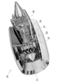
- FIG. 2 is a diagram showing a configuration of an aircraft jet engine 20 provided with such a blade 10.
- the jet engine 20 includes a fan 21, a low pressure compressor 22, an intermediate pressure compressor 23, a high pressure compressor 24, a combustion chamber 25, and a turbine 26 along the rotation axis from the intake port to the exhaust port. .
- the blade 10 is provided in the high-pressure compressor 24 among these.
- the blade of the present embodiment can be applied to any aircraft jet engine compressor, and is not limited to the blade of the high-pressure compressor 24.
- the present invention can be applied to the blades of the low-pressure compressor 22 and the intermediate-pressure compressor 23.
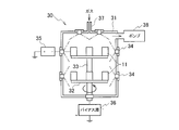
- FIG. 3 is a view showing a film forming apparatus for forming a coating on the blade 10.
- the film forming apparatus 30 stores the base material 11 in a chamber 31 and forms a coating with an amorphous layer on the surface of the base material 11 by physical vapor deposition (PVD) such as vapor deposition.
- PVD physical vapor deposition
- the substrate 11 is supported by a table 32 in a chamber 31, and the table 32 is rotated at a predetermined speed by a rotating shaft 33.
- a plurality of evaporation sources 34 are provided on the inner wall of the chamber 31, and a vapor deposition material for forming a coating is vaporized.
- the evaporation source 34 is supplied with power from an evaporation source power source 35, and the substrate 11 is supplied with a bias voltage from a bias source 36. Further, gas is supplied to the chamber 31 from the air inlet 37 and exhausted by the vacuum pump 38, so that the inside of the chamber 31 is maintained in a predetermined atmosphere.
- the base material 11 stored in the chamber 31 of the film forming apparatus 30 is coated with an amorphous layer on the surface by depositing a deposition material over a predetermined time.
- the properties of the amorphous layer can be adjusted by the deposition rate, film formation rate, and the like.
- the coating formed on the substrate 11 can be deposited at a high speed so as to be amorphous without being crystallized.
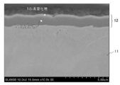
- FIG. 4 is a view showing a microscopic image of the blade 10 on which the coating 12 is formed. This microscopic image is obtained by enlarging the cross section of the coating 12 formed on the surface of the base material 11 by a scanning electron microscope about 10,000 times when an AlTiSiN material is deposited.
- the AlTiSiN material deposited on the surface of the substrate 11 is divided into two layers, a TiAl nitride layer having a thickness of several ⁇ m is formed on the substrate, and a TiSi nitride layer thinner than 1 ⁇ m is formed thereon. Is formed.
- the coating 12 was formed on a round bar-shaped test piece 61 made of the material, and the adhesion of sand was compared.
- a high-speed and high-speed air flow in an operating high-pressure compressor is reproduced using a high-speed burner rig apparatus, and powder of calcium sulfate (CaSO 4 ) simulating sand is sprayed on a test piece 61 to form sand.
- CaSO 4 calcium sulfate
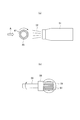
- FIG. 5 is a diagram showing a state of a test for adhesion of sand to the test piece 61 using a burner rig apparatus.
- powder of CaSO 4 was sprayed on the test piece 61 twice using a burner rig apparatus arranged as shown in the figure.
- the average particle size of the powder was about 1.5 ⁇ m.
- the calcium sulfate powder is sprayed together with the flame 52 from the combustor 51 toward the test piece holder 55 that holds the test piece 61 on the circumference and rotates.
- the flame 52 and the calcium sulfate powder were applied to the piece 61 evenly.
- FIG. 5B is according to arrow A in FIG. 5A, and the test piece 61 held by the test piece holder 55 rotated by the rotating shaft 56 burns flame and calcium sulfate powder. It is made to be located in front of the vessel 51.
- the blade 10 having the base material 11 made of the material of the test piece 61 having low sand adhesion By using the blade 10 having the base material 11 made of the material of the test piece 61 having low sand adhesion, sand can be prevented from accumulating on the blade 10, and the aerodynamic performance can be reduced. In addition, the fuel consumption of the jet engine can be prevented from decreasing.
- Example 2 erosion resistance characteristics of various materials included in the coating 12 were examined.
- the values of parameters [(strength) 3 / (elastic modulus) 2 ] generally related to the erosion resistance are shown in Table 2 for each component contained in each coating 12.
- the value of the parameter [(strength) 3 / (elastic modulus) 2 ] is high, the erosion resistance is improved and sand accumulation is prevented.
- the value of the parameter [(strength) 3 / (elastic modulus) 2 ] is preferably 20 or more, and more preferably 40 or more.
- Example 3 the effect of surface roughness on sand adhesion was further compared.
- a predetermined surface roughness that does not deteriorate the aerodynamic performance is formed on the surface of the round bar-shaped test piece 61 having the same material as the base material 11 of the blade 10, and the TiAlN coating 12 is formed thereon. did. And the weight change with respect to the test piece without a coating was measured.
Landscapes
- Engineering & Computer Science (AREA)
- Mechanical Engineering (AREA)
- Chemical & Material Sciences (AREA)
- General Engineering & Computer Science (AREA)
- Chemical Kinetics & Catalysis (AREA)
- Materials Engineering (AREA)
- Metallurgy (AREA)
- Organic Chemistry (AREA)
- Structures Of Non-Positive Displacement Pumps (AREA)
- Physical Vapour Deposition (AREA)
Abstract
L'invention concerne une aube de compresseur pour un moteur à réaction d'avion, qui permet d'empêcher le dépôt de sable en cours de fonctionnement dans des régions désertiques, et pour laquelle un revêtement de couche amorphe est formé sur la surface de l'aube. La couche amorphe comprend au moins un composant parmi TiAlSiN, TiAlCrN, AlCrSiN, AlTiSiN, TiCN, et DLC, et comprend de préférence AlTiSiN. En outre, la surface de l'aube est formée avec une rugosité de surface prescrite, et un revêtement peut être formé dessus, la rugosité de surface étant de préférence inférieure à 0,1 Ra.
Applications Claiming Priority (2)
| Application Number | Priority Date | Filing Date | Title |
|---|---|---|---|
| JP2013-119563 | 2013-06-06 | ||
| JP2013119563A JP2014238014A (ja) | 2013-06-06 | 2013-06-06 | 航空機用ジェットエンジンの圧縮機のブレード及びその表面処理方法 |
Publications (1)
| Publication Number | Publication Date |
|---|---|
| WO2014196634A1 true WO2014196634A1 (fr) | 2014-12-11 |
Family
ID=52008263
Family Applications (1)
| Application Number | Title | Priority Date | Filing Date |
|---|---|---|---|
| PCT/JP2014/065104 Ceased WO2014196634A1 (fr) | 2013-06-06 | 2014-06-06 | Aube de compresseur de moteur à réaction d'avion et procédé de traitement de surface de celle-ci |
Country Status (2)
| Country | Link |
|---|---|
| JP (1) | JP2014238014A (fr) |
| WO (1) | WO2014196634A1 (fr) |
Cited By (9)
| Publication number | Priority date | Publication date | Assignee | Title |
|---|---|---|---|---|
| WO2016104303A1 (fr) * | 2014-12-25 | 2016-06-30 | 株式会社Ihi | Pale de compresseur pour moteur |
| CN109338303A (zh) * | 2018-10-29 | 2019-02-15 | 中国科学院宁波材料技术与工程研究所 | 一种用于锆合金防护的非晶与纳米晶复合涂层及其制备方法 |
| CN109898051A (zh) * | 2019-03-29 | 2019-06-18 | 中南大学 | 一种抗磨损耐腐蚀的DLC/SiNx复合薄膜及其制备方法 |
| WO2019128904A1 (fr) * | 2017-12-29 | 2019-07-04 | 安徽工业大学 | Revêtement alcrsin utilisant une source d'ions améliorée et ayant une teneur en si et taille d'ions variables, à gradient |
| USD885438S1 (en) * | 2019-10-05 | 2020-05-26 | Mountain Aerospace Research Solutions, Inc. | Engine |
| US10961952B1 (en) | 2020-01-29 | 2021-03-30 | Mountain Aerospace Research Solutions, Inc. | Air-breathing rocket engine |
| US11002225B1 (en) | 2020-01-29 | 2021-05-11 | Mountain Aerospace Research Solutions, Inc. | Air-breathing rocket engine |
| US11174817B2 (en) | 2020-01-29 | 2021-11-16 | Mountain Aerospace Research Solutions, Inc. | Air-Breathing rocket engine |
| US11220979B1 (en) | 2020-11-10 | 2022-01-11 | Mountain Aerospace Research Solutions, Inc. | Liquid-cooled air-breathing rocket engine |
Families Citing this family (2)
| Publication number | Priority date | Publication date | Assignee | Title |
|---|---|---|---|---|
| JP2016196820A (ja) | 2015-04-02 | 2016-11-24 | 株式会社Ihi | エンジン用圧縮機翼 |
| CN108486537B (zh) * | 2018-03-09 | 2020-05-12 | 中国科学院宁波材料技术与工程研究所 | 一种用于锆合金的非晶防护涂层及其制备方法和应用 |
Citations (4)
| Publication number | Priority date | Publication date | Assignee | Title |
|---|---|---|---|---|
| JP2009138674A (ja) * | 2007-12-07 | 2009-06-25 | Tocalo Co Ltd | 圧縮機翼及びその製造方法、並びに、火力発電用ガスタービン |
| JP2010090892A (ja) * | 2008-10-03 | 2010-04-22 | General Electric Co <Ge> | タービン稼働中の粒子蓄積を低減させるためのタービン部品の表面処理 |
| JP2010209913A (ja) * | 2009-03-06 | 2010-09-24 | General Electric Co <Ge> | 耐エロージョン性・耐食性タービン圧縮機翼形部及びその製造方法 |
| JP5140200B2 (ja) * | 2011-06-17 | 2013-02-06 | 株式会社神戸製鋼所 | 硬質皮膜被覆部材 |
-
2013
- 2013-06-06 JP JP2013119563A patent/JP2014238014A/ja active Pending
-
2014
- 2014-06-06 WO PCT/JP2014/065104 patent/WO2014196634A1/fr not_active Ceased
Patent Citations (4)
| Publication number | Priority date | Publication date | Assignee | Title |
|---|---|---|---|---|
| JP2009138674A (ja) * | 2007-12-07 | 2009-06-25 | Tocalo Co Ltd | 圧縮機翼及びその製造方法、並びに、火力発電用ガスタービン |
| JP2010090892A (ja) * | 2008-10-03 | 2010-04-22 | General Electric Co <Ge> | タービン稼働中の粒子蓄積を低減させるためのタービン部品の表面処理 |
| JP2010209913A (ja) * | 2009-03-06 | 2010-09-24 | General Electric Co <Ge> | 耐エロージョン性・耐食性タービン圧縮機翼形部及びその製造方法 |
| JP5140200B2 (ja) * | 2011-06-17 | 2013-02-06 | 株式会社神戸製鋼所 | 硬質皮膜被覆部材 |
Cited By (12)
| Publication number | Priority date | Publication date | Assignee | Title |
|---|---|---|---|---|
| WO2016104303A1 (fr) * | 2014-12-25 | 2016-06-30 | 株式会社Ihi | Pale de compresseur pour moteur |
| US10619644B2 (en) | 2014-12-25 | 2020-04-14 | Ihi Corporation | Compressor vane or blade for engine |
| WO2019128904A1 (fr) * | 2017-12-29 | 2019-07-04 | 安徽工业大学 | Revêtement alcrsin utilisant une source d'ions améliorée et ayant une teneur en si et taille d'ions variables, à gradient |
| US10941479B2 (en) | 2017-12-29 | 2021-03-09 | Anhui DuojinTuceng Technology Co. Ltd. | Ion source enhanced AlCrSiN coating with gradient Si content and gradient grain size |
| CN109338303A (zh) * | 2018-10-29 | 2019-02-15 | 中国科学院宁波材料技术与工程研究所 | 一种用于锆合金防护的非晶与纳米晶复合涂层及其制备方法 |
| CN109898051A (zh) * | 2019-03-29 | 2019-06-18 | 中南大学 | 一种抗磨损耐腐蚀的DLC/SiNx复合薄膜及其制备方法 |
| USD885438S1 (en) * | 2019-10-05 | 2020-05-26 | Mountain Aerospace Research Solutions, Inc. | Engine |
| US10961952B1 (en) | 2020-01-29 | 2021-03-30 | Mountain Aerospace Research Solutions, Inc. | Air-breathing rocket engine |
| US11002225B1 (en) | 2020-01-29 | 2021-05-11 | Mountain Aerospace Research Solutions, Inc. | Air-breathing rocket engine |
| US11174817B2 (en) | 2020-01-29 | 2021-11-16 | Mountain Aerospace Research Solutions, Inc. | Air-Breathing rocket engine |
| US11220979B1 (en) | 2020-11-10 | 2022-01-11 | Mountain Aerospace Research Solutions, Inc. | Liquid-cooled air-breathing rocket engine |
| US11635044B2 (en) | 2020-11-10 | 2023-04-25 | Mountain Aerospace Research Solutions, Inc. | Liquid-cooled air-breathing rocket engine |
Also Published As
| Publication number | Publication date |
|---|---|
| JP2014238014A (ja) | 2014-12-18 |
Similar Documents
| Publication | Publication Date | Title |
|---|---|---|
| WO2014196634A1 (fr) | Aube de compresseur de moteur à réaction d'avion et procédé de traitement de surface de celle-ci | |
| JP5441596B2 (ja) | タービン稼働中の粒子蓄積を低減させるためのタービン部品の表面処理 | |
| CN108431290B (zh) | 涡轮间隙控制涂层和方法 | |
| CN111005002B (zh) | 一种压气机叶片耐冲蚀防腐蚀自洁涂层的制备方法 | |
| US20140272166A1 (en) | Coating system for improved leading edge erosion protection | |
| EP2258889B1 (fr) | Procédé et appareillage d'application d'un revêtement de barrière thermique | |
| US20090191347A1 (en) | Turbine component other than airfoil having ceramic corrosion resistant coating and methods for making same | |
| US20140301861A1 (en) | Airfoil having an erosion-resistant coating thereon | |
| KR20080037578A (ko) | 내침식성 코팅 및 그의 제조방법 | |
| US11946147B2 (en) | Thermal barrier coating, turbine member, gas turbine, and method for producing thermal barrier coating | |
| GB2477869A (en) | Process for depositing a coating on a blisk | |
| CN107002706B (zh) | 发动机用压缩机叶片 | |
| US10619644B2 (en) | Compressor vane or blade for engine | |
| JP7214120B2 (ja) | 硬質皮膜被覆部材及びその製造方法 | |
| US20250389193A1 (en) | Variable thickness coating control | |
| JP2018535322A (ja) | タービンのクリアランス制御コーティング及び方法 | |
| Reedy | The development and synthesis of multifunctional erosion and corrosion resistant titanium-chromium-nitride coatings for turbomachinery applications | |
| JP2017088937A (ja) | 耐食性コーティングを有するエンジン用圧縮機翼およびそのコーティング方法 | |
| FR2682400A1 (fr) | Materiau multicouche, procedes de fabrication de ce materiau multicouche et de l'une des couches de ce materiau et revetement anti-erosion et anti-abrasion comprenant ce materiau multicouche. | |
| JP2011074797A (ja) | ブレード、ブレードの製造方法、及び、回転機械 |
Legal Events
| Date | Code | Title | Description |
|---|---|---|---|
| 121 | Ep: the epo has been informed by wipo that ep was designated in this application |
Ref document number: 14807537 Country of ref document: EP Kind code of ref document: A1 |
|
| NENP | Non-entry into the national phase |
Ref country code: DE |
|
| 122 | Ep: pct application non-entry in european phase |
Ref document number: 14807537 Country of ref document: EP Kind code of ref document: A1 |