WO2014196668A1 - Article absorbant et article à porter pourvu dudit article absorbant - Google Patents
Article absorbant et article à porter pourvu dudit article absorbant Download PDFInfo
- Publication number
- WO2014196668A1 WO2014196668A1 PCT/JP2014/069092 JP2014069092W WO2014196668A1 WO 2014196668 A1 WO2014196668 A1 WO 2014196668A1 JP 2014069092 W JP2014069092 W JP 2014069092W WO 2014196668 A1 WO2014196668 A1 WO 2014196668A1
- Authority
- WO
- WIPO (PCT)
- Prior art keywords
- nonwoven fabric
- absorbent article
- fiber
- top sheet
- thickness
- Prior art date
- Legal status (The legal status is an assumption and is not a legal conclusion. Google has not performed a legal analysis and makes no representation as to the accuracy of the status listed.)
- Ceased
Links
Images





Classifications
-
- A—HUMAN NECESSITIES
- A61—MEDICAL OR VETERINARY SCIENCE; HYGIENE
- A61F—FILTERS IMPLANTABLE INTO BLOOD VESSELS; PROSTHESES; DEVICES PROVIDING PATENCY TO, OR PREVENTING COLLAPSING OF, TUBULAR STRUCTURES OF THE BODY, e.g. STENTS; ORTHOPAEDIC, NURSING OR CONTRACEPTIVE DEVICES; FOMENTATION; TREATMENT OR PROTECTION OF EYES OR EARS; BANDAGES, DRESSINGS OR ABSORBENT PADS; FIRST-AID KITS
- A61F13/00—Bandages or dressings; Absorbent pads
- A61F13/15—Absorbent pads, e.g. sanitary towels, swabs or tampons for external or internal application to the body; Supporting or fastening means therefor; Tampon applicators
- A61F13/51—Absorbent pads, e.g. sanitary towels, swabs or tampons for external or internal application to the body; Supporting or fastening means therefor; Tampon applicators characterised by the outer layers of the pads
- A61F13/511—Topsheet, i.e. the permeable cover or layer facing the skin
- A61F13/51104—Topsheet, i.e. the permeable cover or layer facing the skin the top sheet having a three-dimensional cross-section, e.g. corrugations, embossments, recesses or projections
-
- A—HUMAN NECESSITIES
- A61—MEDICAL OR VETERINARY SCIENCE; HYGIENE
- A61F—FILTERS IMPLANTABLE INTO BLOOD VESSELS; PROSTHESES; DEVICES PROVIDING PATENCY TO, OR PREVENTING COLLAPSING OF, TUBULAR STRUCTURES OF THE BODY, e.g. STENTS; ORTHOPAEDIC, NURSING OR CONTRACEPTIVE DEVICES; FOMENTATION; TREATMENT OR PROTECTION OF EYES OR EARS; BANDAGES, DRESSINGS OR ABSORBENT PADS; FIRST-AID KITS
- A61F13/00—Bandages or dressings; Absorbent pads
- A61F13/15—Absorbent pads, e.g. sanitary towels, swabs or tampons for external or internal application to the body; Supporting or fastening means therefor; Tampon applicators
- A61F13/53—Absorbent pads, e.g. sanitary towels, swabs or tampons for external or internal application to the body; Supporting or fastening means therefor; Tampon applicators characterised by the absorbing medium
- A61F13/534—Absorbent pads, e.g. sanitary towels, swabs or tampons for external or internal application to the body; Supporting or fastening means therefor; Tampon applicators characterised by the absorbing medium having an inhomogeneous composition through the thickness of the pad
- A61F13/535—Absorbent pads, e.g. sanitary towels, swabs or tampons for external or internal application to the body; Supporting or fastening means therefor; Tampon applicators characterised by the absorbing medium having an inhomogeneous composition through the thickness of the pad inhomogeneous in the plane of the pad, e.g. core absorbent layers being of different sizes
- A61F13/536—Absorbent pads, e.g. sanitary towels, swabs or tampons for external or internal application to the body; Supporting or fastening means therefor; Tampon applicators characterised by the absorbing medium having an inhomogeneous composition through the thickness of the pad inhomogeneous in the plane of the pad, e.g. core absorbent layers being of different sizes having discontinuous areas of compression
Definitions
- the present invention relates to an absorbent article and a wearing article provided with the absorbent article.
- Patent Document 1 describes an absorbent article in which an absorbent body in which through-holes are formed is arranged at a portion where a wearer's genital area abuts. In the absorbent article described in Patent Document 1, it is possible to improve the fit of the absorbent article to the wearer's genital area. Moreover, since the part which a wearer's shadow part contacts is difficult to become a wet state, it is possible to prevent a wearer's discomfort.
- Patent Documents 2 to 13 disclose the use of a nonwoven fabric having a convex portion formed on the surface and the top sheet of the absorbent article.
- the liquid permeability and the touch of the nonwoven fabric can be improved by the convex portions formed on the surface.
- the protrusions formed on the top sheet are crushed by the pressure applied to the absorbent article, and the function of the protrusions (for example, There is a risk that the improvement in liquidity, the improvement in touch, etc.) will be reduced.
- the protrusions formed on the top sheet are easily crushed.
- this invention is an absorbent article provided with the top sheet in which the convex part was formed, Comprising: Even when the top sheet is a wet state, the absorbent article which can maintain the shape of the convex part formed in the top sheet And it aims at providing a wearing article provided with this absorptive article.
- the present invention includes a liquid-permeable top sheet, a liquid-impervious back sheet, and a liquid-absorbing absorber disposed between the top sheet and the back sheet.
- An absorbent article having a length direction, a width direction, and a thickness direction orthogonal to each other, wherein the top sheet is a nonwoven fabric having a skin-side surface on which a convex portion is formed, The content of the thickness direction oriented fibers in the portion is larger than the content of the thickness direction oriented fibers in the portion other than the convex portion of the nonwoven fabric, and the wet thickness of the nonwoven fabric is the thickness of the nonwoven fabric when dried.
- the absorbent article is 85% or more.
- the present invention also includes an exterior body that includes a liquid-permeable top sheet having a mounting surface on which an absorbent article is mounted, and a liquid-impermeable back sheet, and has an abdominal part, a crotch part, and a back part. And an absorbent article of the present invention detachably attached to the attachment surface.
- the absorbent article provided with the top sheet in which the convex part was formed, Comprising: Even when the top sheet is a wet state, the absorbent article which can maintain the shape of the convex part formed in the top sheet And a wearing article provided with this absorptive article is provided.
- FIG. 1 is a plan view of a urine collecting pad according to an embodiment of the present invention.
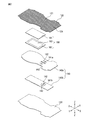
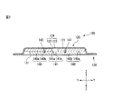
- FIG. 2 is an exploded perspective view of the urine collection pad shown in FIG. 3 is an end view taken along line AA of FIG. 4A is an end view taken along the line BB in FIG. 1 (part on the abdomen side), and
- FIG. 4B is an end view taken along line BB in FIG. ).
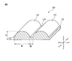
- FIG. 5 is an enlarged perspective view of a part of the top sheet provided in the urine collecting pad shown in FIG. 1.
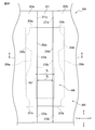
- FIG. 6 is a plan view of an exterior body according to an embodiment of the present invention.
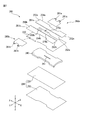
- 7 is an exploded perspective view of the exterior body shown in FIG.
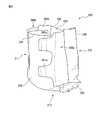
- FIG. 8 is a perspective view showing a state in which the exterior body shown in FIG. 6 is deformed into a pants shape.
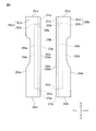
- FIG. 9 is a diagram for explaining a side sheet provided in the exterior body illustrated in FIG. 6.
- FIG. 10 is a partially enlarged plan view of a wearing article according to an embodiment of the present invention.
- 11 is a cross-sectional view taken along line AA in FIG.
- FIG. 12A is an overall view of the nonwoven fabric manufacturing apparatus
- FIG. 12B is an enlarged perspective view of an injection unit of the nonwoven fabric manufacturing apparatus.
- FIG. 13 is a diagram for explaining the action of the gas injected from the injection unit on the web.
- the proximal side of the virtual center line extending in the width direction through the center of the absorbent article is expressed as “inner of the length direction” and the distal side is expressed as “ It may be expressed as “outside in the length direction”.
- the proximal side of the virtual center line extending in the length direction through the center of the absorbent article is expressed as “inner side in the width direction”
- the distal side is expressed as “width direction” It may be expressed as “outside”.
- one side in the thickness direction located on the wearer's skin side is referred to as “skin side”
- the other side in the thickness direction located on the wearer's clothing side is referred to as “clothing side” "
- An absorbent article according to an aspect of the present invention (hereinafter referred to as “Aspect 1A”) is disposed between a liquid-permeable top sheet, a liquid-impermeable back sheet, and the top sheet and the back sheet.
- the content rate of the thickness direction oriented fiber in the convex portion of the nonwoven fabric is larger than the content rate of the thickness direction oriented fiber in the portion other than the convex portion of the nonwoven fabric, and the wet thickness of the nonwoven fabric is
- the absorbent article is 85% or more of the dry thickness of the nonwoven fabric.
- the absorbent article according to aspect 1A can exhibit the following effects.
- the nonwoven fabric has a wet thickness of 85% or more of the dry thickness of the nonwoven fabric because the thickness direction oriented fiber content of the convex portion of the nonwoven fabric is larger than the thickness direction oriented fiber content of the other portions. Has been. Therefore, when the absorbent article is worn, the shape of the convex portions formed on the top sheet is easily maintained even when the top sheet is in a wet state by the liquid supplied to the absorbent article.
- Urine of elderly people contains more impurities than urine of general adults. Therefore, when the convex part formed in the top sheet is crushed and the bulk and voids of the convex part are reduced, impurities in urine are likely to remain in the top sheet, causing a decrease in liquid permeability of the top sheet.
- the absorbent article according to aspect 1A is easy to maintain the bulk and voids of the convex portion, and therefore, an absorbent article for absorbing urine of an elderly person (especially a bedridden elderly person) (for example, a urine collecting pad). It is suitable as.
- An elderly person usually means a person 65 years or older.
- the thickness of the nonwoven fabric when dried is 0.6 to 1.6 mm.
- a dry thickness of the nonwoven fabric of 0.6 to 1.6 mm is a preferable condition for realizing a wet thickness of the nonwoven fabric of 85% or more of the dry thickness of the nonwoven fabric.
- the basis weight of the nonwoven fabric is 18 to 40 g / m 2 .
- a basis weight of the nonwoven fabric of 18 to 40 g / m 2 is a preferable condition for realizing a wet thickness of the nonwoven fabric of 85% or more of the dry thickness of the nonwoven fabric.
- the nonwoven fabric has a concavo-convex structure formed by jetting a gas onto a web containing thermoplastic resin fibers. Then, it is a nonwoven fabric manufactured by heat-processing and heat-bonding the intersection part of the thermoplastic resin fibers in the said web.
- the nonwoven fabric is manufactured by injecting a gas onto a web containing thermoplastic resin fibers to form a concavo-convex structure, and then heat-treating and cross-bonding the intersecting portions of the thermoplastic resin fibers in the web. Is a preferable condition for realizing a wet thickness of the nonwoven fabric of 85% or more of the dry thickness of the nonwoven fabric.
- the non-woven fabric includes a first fiber layer having the skin-side surface, and more than the first fiber layer.
- a second fiber layer positioned on the absorber side, and an average fiber diameter in the first fiber layer is smaller than an average fiber diameter in the second fiber layer.
- the average fiber diameter in the first fiber layer is smaller than the average fiber diameter in the second fiber layer, the touch on the skin side surface of the top sheet is improved.
- the average fiber diameter in the second fiber layer being larger than the average fiber diameter in the first fiber layer is a preferable condition for realizing a wet thickness of the nonwoven fabric that is 85% or more of the dry thickness of the nonwoven fabric. .
- the second fiber layer contains an eccentric core-sheath type composite fiber
- the first fiber layer has an eccentric core-sheath type composite fiber.
- the fact that the second fiber layer contains an eccentric core-sheath type composite fiber and the first fiber layer does not contain an eccentric core-sheath type composite fiber means that the wet thickness of the nonwoven fabric is 85% or more of the dry thickness of the nonwoven fabric. This is a preferable condition for realizing.
- the durable hydrophilicity of the first fiber layer is greater than the durable hydrophilicity of the second fiber layer.
- the hydrophilicity of the second fiber layer is more likely to be lower than the hydrophilicity of the first fiber layer, so that the liquid absorbed in the absorber is the second fiber layer. It is difficult to return to the first fiber layer.
- the absorber is a through-hole penetrating the absorber in the thickness direction or the top sheet side.
- the through-hole or the recess extending in the length direction through the center in the width direction of the absorber.
- the skin-side surface of the top sheet is convex toward the clothing side (back sheet side) with a portion other than the convex portion (for example, a concave portion) as a starting point by the force toward the inner side in the width direction applied when the absorbent article is worn.
- the absorbent body tends to be convexly deformed on the skin side (top sheet side).
- the top sheet tends to enter the through hole or the recess of the absorbent body. For this reason, even if a top sheet is pressed at the time of wear of an absorptive article, the portion which entered into the penetration hole or crevice of an absorber among top sheets is hard to be pressed, and the shape of the convex part in this portion is easy to be maintained. .
- the absorbent body is a pressing part that integrates the absorbent body in the thickness direction, and is more than the through hole or the recessed part. Also has the pressing part formed on the outer side in the width direction. Due to the force toward the inner side in the width direction applied when the absorbent article is worn, the absorbent body tends to be convexly deformed to the skin side with the squeezed portion as the starting point. Therefore, when the absorbent article is worn, the top sheet tends to enter the through hole or the recess of the absorbent body. Moreover, since the shape of the through-hole or recessed part of an absorber is easy to be hold
- the convex portion is a collar portion extending in the length direction. It is a preferable condition for realizing the wet thickness of the non-woven fabric that is 85% or more of the dry thickness of the non-woven fabric so that the convex portion extends in the length direction.
- a wearing article according to an aspect of the present invention includes a liquid-permeable top sheet having a mounting surface on which an absorbent article is mounted, and a liquid-impermeable back sheet.
- a worn article comprising: an exterior body having a side part, a crotch part, and a back side part; and an absorbent article according to any one of aspects 1A to 10A, which is detachably attached to the attachment surface. .
- the wearing article according to aspect 1B can exhibit the same effects as the absorbent article according to aspects 1A to 10A, depending on the aspect of the absorbent article to be mounted.
- the type and application of the absorbent article of the present invention are not particularly limited.
- absorbent articles include sanitary products such as urine collection pads, disposable diapers, sanitary napkins, panty liners, etc., and these may be used for humans and non-human animals such as pets.
- the liquid to be absorbed by the absorbent article of the present invention is not particularly limited, and examples thereof include liquid excrement (for example, urine, watery stool, menstrual blood, etc.) of the wearer.
- FIG. 1 is a plan view of the urine collection pad 100
- FIG. 2 is an exploded perspective view of the urine collection pad 100
- FIG. 3 is an end view taken along line AA of FIG. 1
- FIG. 5 is an end view taken along the line BB of FIG. 1 (A is a portion on the ventral side, B is a portion on the back side)
- FIG. 5 is a partially enlarged perspective view of the top sheet 120.
- the urine collecting pad 100 has a length direction X, a width direction Y, and a thickness direction Z orthogonal to each other in the extended state.
- the urine absorbing pad 100 is disposed between a liquid-permeable top sheet 120 having a skin-side surface 121, a liquid-impermeable back sheet 130 having a clothing-side surface 131, and the top sheet 120 and the back sheet 130.
- a liquid-absorbing absorber 140 is disposed between a liquid-permeable top sheet 120 having a skin-side surface 121, a liquid-impermeable back sheet 130 having a clothing-side surface 131, and the top sheet 120 and the back sheet 130.
- a liquid-absorbing absorber 140 is disposed between a liquid-permeable top sheet 120 having a skin-side surface 121, a liquid-impermeable back sheet 130 having a clothing-side surface 131, and the top sheet 120 and the back sheet 130.
- the urine collecting pad 100 has an abdominal side part 111, a crotch part 112, and a back side part 113 arranged in the length direction X.
- the abdomen 111 is applied to the wearer's abdomen
- the crotch 112 is applied to the wearer's crotch
- the back 113 is the wearer's buttocks and / or back.
- the length of the urine absorbing pad 100 is usually 350 to 880 mm, and the width is usually 160 to 460 mm.
- the urine removing pad 100 is worn such that the skin side surface 121 of the top sheet 120 is located on the wearer's skin side and the clothing side surface 131 of the back sheet 130 is located on the wearer's clothing side.
- the urine absorbing pad 100 is preferably worn in a state of being mounted on an exterior body 200 described later. Since the shape of the urine absorbing pad 100 in a plan view is a bowl shape with a substantially central portion in the length direction X being constricted, the constricted portion of the urine collecting pad 100 can easily fit between the wearer's crotch.
- the urine excreted from the wearer penetrates the absorber 140 through the top sheet 120 and is absorbed and held by the absorber 140. Leakage of urine absorbed and held by the absorber 140 is prevented by the back sheet 130.
- the liquid-permeable sheet used as the top sheet 120 is a nonwoven fabric.
- the nonwoven fabric include air-through nonwoven fabric, spunbond nonwoven fabric, point bond nonwoven fabric, spunlace nonwoven fabric, needle punch nonwoven fabric, melt blown nonwoven fabric, and combinations thereof (for example, spunbond / meltblown / spunbond (SMS) nonwoven fabric).
- SMS spunbond / meltblown / spunbond
- An air-through nonwoven fabric is preferable.
- the basis weight of the nonwoven fabric used as the top sheet 120 is appropriately adjusted in consideration of liquid permeability, touch and the like.
- a collar portion 122 (an example of a convex portion) is formed on the skin side surface 121 of the top sheet 120.
- the convex part formed on the skin side surface 121 of the top sheet 120 is the ridge part 122 extending in the length direction X in order to realize a wet thickness of the nonwoven fabric that is 85% or more of the dry thickness of the nonwoven fabric. This is a preferable condition.
- the flanges 122 extend in the length direction X and are arranged at a predetermined interval in the width direction Y, and one groove 123 is formed between two adjacent flanges 122.
- the skin-side surface 121 is formed with a ridge groove structure 124 including a plurality of ridges 122 extending in the length direction X and a plurality of grooves 123 extending in the length direction X.
- a ridge groove structure 124 including a plurality of ridges 122 extending in the length direction X and a plurality of grooves 123 extending in the length direction X.
- one flange 122 is shown as a region between two adjacent lines, and one groove 123 is shown by one line.
- a part of the ridge groove structure 124 formed on the skin side surface 121 is omitted in FIG.
- the BB line shown in FIG. 1 is a line passing through the flange 122, the groove 123 does not appear in the end view of the BB line (FIG. 4).
- the urine supplied to the top sheet 120 extends in the length direction X along the ridge portion 122 and the groove portion 123. It is advantageous in that it is easy to spread, and it is possible to prevent urine from spreading in the width direction Y and leakage of urine from the urine collecting pad 100 due to this.
- the form of the collar part 122 and the groove part 123 is changeable.
- the flange portion 122 and the groove portion 123 extend in the width direction Y and are aligned in the length direction X, and the flange portion 122 and the groove portion 123 extend while changing directions (for example, in a wavy shape).
- the embodiment in which the flange 122 and the groove 123 extend intermittently in the length direction X, and the like.
- the surface of the flange 122 is a curved surface, and the cross-sectional shape of the flange 122 is a substantially inverted U shape toward the surface.
- the cross-sectional shape of the flange 122 can be changed.
- embodiment whose cross-sectional shape of the collar part 122 is trapezoid shape, a triangular shape, etc. is mentioned, for example.
- the groove portion 123 is formed even when the collar portion 122 is crushed by the force applied to the urine collecting pad 100 (for example, body pressure of the wearer). This is advantageous in that it can maintain the space.
- the flange portion 122 has a thickness T1
- the groove portion 123 has a thickness T2.
- the thickness T1 of the flange 122 is usually 0.3 to 1.5 mm, preferably 0.6 to 1.4 mm, more preferably 0.8 to 1.2 mm
- the thickness T2 of the groove 123 is usually The thickness is 0.1 to 0.5 mm, preferably 0.2 to 0.4 mm, and more preferably 0.2 to 0.3 mm.
- the thickness of the buttock and groove is measured by measuring a 100 mm ⁇ 100 mm top sheet sample cut out from the urine collection pad and a laser displacement meter (for example, a high-precision two-dimensional laser displacement meter LJ-G series manufactured by Keyence Corporation (model: Using LJ-G030)) in a non-contact manner as follows.
- a top sheet sample is placed on a horizontal measuring table, and the displacement from the measuring table is measured with a laser displacement meter for five different collars, and the average value of the five measurements is defined as the thickness (mm) of the collar. .
- the displacement from a measurement stand is measured with a laser displacement meter, and let the average value of five measured values be the thickness (mm) of a groove part.
- the flange portion 122 has a width W1, and the groove portion 123 has a width W2.
- the width W1 of the flange 122 is usually 2.0 to 5.0 mm, preferably 3.0 to 4.0 mm, and the width W2 of the groove 123 is usually 1.0 to 3.0 mm, preferably 1.0. ⁇ 2.0 mm.
- the interval between the two adjacent flange portions 122 is usually equal to the width W2 of the groove portion, and the interval between the two adjacent groove portions 123 is usually equal to the width of the flange portion 122.
- the width W1 of the flange 122 is measured as a distance between the boundary lines of the flange 122 and the two groove portions 123 located on both sides thereof based on a plane photograph or a plane image of the top sheet 120 in a non-pressurized state.
- the width W2 of the groove 123 is the same.
- the thickness and width of the flange 122 are substantially the same in any flange, but there may be a flange having a thickness or width different from other flanges. The same applies to the thickness and width of the groove 122.
- the content ratio of the thickness direction oriented fibers in the ridge portion 122 is greater than the content ratio of the thickness direction oriented fibers in a portion of the nonwoven fabric other than the ridge portion 122 (for example, the groove portion 123). large.
- “Thickness-oriented fibers” are fibers that are oriented at an angle of +45 degrees to ⁇ 45 degrees with respect to the thickness direction Z.
- the content ratio of the thickness-oriented fibers in the collar portion 122 is preferably 55 to 100%, more preferably 60 to 100%.
- the difference between the content of the thickness-oriented fibers in the ridge portion 122 and the content of the thickness-oriented fibers in the portion of the nonwoven fabric other than the ridge portion 122 is preferably 10 to 100%, Preferably it is 20 to 100%.
- the measuring method of the content rate of the thickness direction orientation fiber in the predetermined part of a nonwoven fabric is as follows. (1) Cut the nonwoven fabric to produce a nonwoven fabric sample. (2) Using a digital microscope VHX-100 manufactured by Keyence Corporation, take an enlarged image from a direction perpendicular to the cut surface of the nonwoven fabric sample.
- the magnified image is an image magnified to a magnification that allows measurement of 50 or more fibers, and the magnification is, for example, 20 to 50 times.
- focus on the fiber nearest to the cut surface of the non-woven fabric sample excluding fibers that have irregularly jumped forward
- set the shooting depth (depth) The enlarged image is created on the PC screen as a 3D image.
- a 3D image is converted into a 2D image, and a plurality of lines extending parallel to the thickness direction of the nonwoven fabric sample are drawn on the 2D image, and +45 degrees to -45 degrees with respect to the thickness direction of the nonwoven fabric sample.
- the number of fibers oriented at an angle of is counted.
- the ratio of the number of counted fibers to the number of all fibers in the measurement range is calculated.
- (1) to (4) are repeated several times (for example, 3 to 5 times), and the average value is taken as the content of the fiber in the thickness direction.
- the wet thickness of the nonwoven fabric used as the top sheet 120 is 85% or more, preferably 90% or more of the dry thickness of the nonwoven fabric.
- the measuring method of the dry thickness and wet thickness of the nonwoven fabric is as follows.
- the nonwoven fabric which adjusted the state is used for the measurement of the various parameters of a nonwoven fabric.
- Conditioning of the nonwoven fabric is carried out by storing the nonwoven fabric in a dry state for 24 hours or longer in a standard state (temperature 23 ⁇ 2 ° C., relative humidity 50 ⁇ 5%).
- the non-woven fabric in a dry state is a non-woven fabric having a moisture content of usually 12% or less, preferably 10% or less, and more preferably 8% or less.
- a thickness meter for example, FS-60DS manufactured by Daiei Kagaku Seiki Seisakusho Co., Ltd., measuring element area 15 cm 2
- three different parts of the nonwoven fabric after conditioning when using thickness meter FS-60DS, The area of each part is 15 cm 2 ) at a constant pressure of 3 g / cm 2 , and the thickness after 10 seconds at each part is measured.
- the same measurement is performed for each of the ten nonwoven fabrics, and the average value of the total of 30 measurement values is defined as the thickness of the nonwoven fabric when dried.
- the dry thickness of the nonwoven fabric used as the top sheet 120 is preferably 0.6 to 1.6 mm, more preferably 0.8 to 1.4 mm. This condition is a preferable condition for realizing a wet thickness of the nonwoven fabric of 85% or more of the dry thickness of the nonwoven fabric.
- the basis weight of the nonwoven fabric used as the top sheet 120 is preferably 18 to 40 g / m 2 , more preferably 25 to 35 g / m 2 .
- This condition is a preferable condition for realizing a wet thickness of the nonwoven fabric of 85% or more of the dry thickness of the nonwoven fabric.
- the measuring method of the basic weight of a nonwoven fabric is as follows.
- the mass of three test pieces (10 mm ⁇ 10 mm) cut out from the nonwoven fabric after conditioning was measured with a direct balance (for example, electronic balance HF-300 manufactured by Kensei Kogyo Co., Ltd.).
- a direct balance for example, electronic balance HF-300 manufactured by Kensei Kogyo Co., Ltd.
- the mass per unit area (g / m ⁇ 2 >) of the nonwoven fabric computed from the average value of mass be a basic weight of a nonwoven fabric.
- the non-woven fabric in which the ridge groove structure 124 is formed is formed by, for example, forming a ridge groove structure on a web containing thermoplastic resin fibers, and then heat-treating the intersecting portions of the thermoplastic resin fibers in the web. Can be manufactured. Such a manufacturing method is a preferable condition for realizing a wet thickness of the nonwoven fabric of 85% or more of the dry thickness of the nonwoven fabric.
- heat processing are implemented by spraying a hot air with respect to a web.
- thermoplastic resin constituting the thermoplastic resin fiber contained in the web examples include polyolefin, polyester, polyamide, and the like.
- polyolefin examples include, for example, linear low density polyethylene (LLDPE), low density polyethylene (LDPE), medium density polyethylene (MDPE), high density polyethylene (HDPE), polypropylene, polybutylene, and copolymers based on these (for example, Ethylene-vinyl acetate copolymer (EVA), ethylene-ethyl acrylate copolymer (EEA), ethylene-acrylic acid copolymer (EAA), ionomer resin) and the like.
- LLDPE linear low density polyethylene
- LDPE low density polyethylene
- MDPE medium density polyethylene
- HDPE high density polyethylene
- EVA Ethylene-vinyl acetate copolymer
- EAA ethylene-ethyl acrylate copolymer
- EAA ethylene-acrylic acid copolymer
- polyesters examples include linear or branched carbon atoms of up to 20 including polyethylene terephthalate (PET), polytrimethyl terephthalate (PTT), polybutylene terephthalate (PBT), polylactic acid, and polyglycolic acid. And polyesters such as polyhydroxyalkanoic acid, copolymers based on these, and copolymerized polyesters obtained by copolymerizing alkylene terephthalate as a main component with a small amount of other components.
- polyamide examples include 6-nylon and 6,6-nylon.
- the thermoplastic resin fiber is preferably subjected to a hydrophilic treatment.
- thermoplastic resin fiber examples include, for example, a treatment using a surfactant, a hydrophilic agent, etc. (for example, kneading a surfactant inside the fiber, coating a surfactant on the fiber surface, etc.) Plasma processing etc. are mentioned.
- a surfactant for example, kneading a surfactant inside the fiber, coating a surfactant on the fiber surface, etc.
- Plasma processing etc. are mentioned.
- the thermoplastic resin fiber may be composed of one kind of thermoplastic resin, but is preferably a composite fiber containing two or more kinds of thermoplastic resins.
- a preferable composite fiber is a core-sheath type composite fiber.
- the thermoplastic resin forming the sheath component of the core-sheath composite fiber a thermoplastic resin having a melting point lower than that of the thermoplastic resin forming the core component is selected.
- the core component of the sheath-core composite fiber and the thermoplastic resin forming the sheath component include olefin resins such as polyethylene and polypropylene, polyamide resins such as nylon, polyester resins, polyacrylonitrile resins, and the like. .
- the thermoplastic resin forming the sheath component is preferably polyethylene (for example, high density polyethylene, low density polyethylene, linear low density polyethylene, a mixture of these polyethylenes, etc.), and the thermoplastic resin forming the core component is Polypropylene and polyester are preferable.
- polyethylene for example, high density polyethylene, low density polyethylene, linear low density polyethylene, a mixture of these polyethylenes, etc.
- thermoplastic resin forming the core component is Polypropylene and polyester are preferable.
- Examples of the method for forming the groove structure on the web include the methods described in JP-A-2008-25079, JP-A-2008-23326, JP-A-2009-30218, and the like. According to these methods, the web is placed on a breathable support member (for example, a net-like support member), and the gas (usually air) is continuously formed on the upper surface of the web while moving the breathable support member in a predetermined direction. By injecting, a grooved structure can be formed on the web.
- the lower surface of the web has a shape along the shape of the breathable support member. For example, when the web placement surface of the net-like support member is flat, the lower surface of the web is substantially flat (therefore, the lower surface of the nonwoven fabric is also substantially flat).
- a groove portion extending in the moving direction of the air-permeable support member is formed in a region of the upper surface of the web where the gas is injected, and a flange portion is formed between two adjacent groove portions.
- region where gas was injected moves to the both sides of a groove part, the basic weight of a collar part becomes higher than the basic weight of a groove part normally.
- the fibers in the web are rolled up by the gas bounced back by colliding with a non-venting portion (for example, a wire) of the air-permeable support member, and the thickness direction orientation in the heel portion of the ridge groove structure formed on the web
- the content rate of the fiber becomes larger than the content rate of the thickness direction oriented fiber in the other portion (for example, the groove).
- the number of ribs and grooves, spacing, basis weight, fiber density, thickness-oriented fiber content, etc. are the number of nozzles, caliber and pitch, temperature and amount of gas injected from the nozzle, web tension, etc. It is possible to adjust to a desired range by adjusting.
- FIG. 12 and FIG. 13 are diagrams for explaining an embodiment of a nonwoven fabric manufacturing apparatus for manufacturing a nonwoven fabric in which the ridge groove structure 124 is formed.
- 12A is an overall view of the nonwoven fabric manufacturing apparatus 300
- FIG. 12B is an enlarged perspective view of the injection unit 330 of the nonwoven fabric manufacturing apparatus 300
- FIG. 13 is injected from the injection unit 330. It is a figure for demonstrating the effect
- the nonwoven fabric manufacturing apparatus 300 includes a gas-permeable support member 310 that supports the web W, a conveyor 320 that moves the gas-permeable support member 310 in a predetermined direction F, and a surface of the web W that is supported by the gas-permeable support member 310. And a heater unit 340 for heat-treating the web W after the gas injection process.
- the air-permeable support member 310 is a net-like support member formed by weaving a plurality of wires having a predetermined thickness that are impermeable portions.
- the breathable support member 310 is formed with a plurality of holes that are ventilation portions by weaving a plurality of wires at a predetermined interval. The hole vents the gas G injected from the injection unit 330 downward.
- the conveyor 320 includes a breathable belt portion 321 that supports the breathable support member 310 and rotating portions 322 and 323 that rotate the breathable belt portion 321 in a predetermined direction.
- the injection unit 330 is connected to an air supply unit (not shown) through an air supply pipe 331 so as to allow ventilation.
- a plurality of injection ports 332 are formed in the injection unit 330 at predetermined intervals.
- the gas G supplied from the air supply unit (not shown) to the injection unit 330 through the air supply pipe 331 is supplied from the plurality of injection ports 332 formed in the injection unit 330 to the web W supported by the air-permeable support member 310.
- the gas G that has passed through the air-permeable support member 310 is sucked by the air intake unit 350 disposed below the injection unit 330.
- the gas G injected from the injection port 332 collides with the air-impermeable portion (wire) of the air-permeable support member 310 and bounces back, so that the fibers in the web W are rolled up and the orientation of the web W in the thickness direction is increased. It improves (refer FIG. 13). Thereby, the content rate of the thickness direction orientation fiber in a collar part becomes larger than the content rate of the thickness direction orientation fiber in a groove part among the groove structure formed in the web W. As shown in FIG.
- the temperature of the gas G injected from the injection port 332 may be normal temperature, but from the viewpoint of improving the moldability of the groove structure, it is equal to or higher than the softening point of the thermoplastic resin fibers constituting the web W,
- the melting point is preferably in the range of + 50 ° C. to ⁇ 50 ° C.
- the web W supported by the air-permeable support member 310 is heated by the heater unit 340 after the gas injection process.
- the web W supported by the air-permeable support member 310 continuously moves in a heating space formed in the heater portion 340 with a stay for a predetermined time.
- the intersecting portion of the thermoplastic resin fibers in the web W is heat-sealed in a state where the groove structure formed in the web W is held, and the groove structure 124 is formed.
- a non-woven fabric is produced.
- the nonwoven fabric used as the top sheet 120 preferably has a first fiber layer having a skin-side surface 121 and a second fiber layer located closer to the absorber 140 than the first fiber layer.
- the average fiber diameter in the first fiber layer is preferably smaller than the average fiber diameter in the second fiber layer. Thereby, the touch in the skin side surface 121 of the top sheet 120 improves.
- the average fiber diameter in the first fiber layer is preferably 1.3 to 3.3 dtex, and the average fiber diameter in the second fiber layer is preferably 2.3 to 4.4 dtex. That the average fiber diameter in the second fiber layer is larger than the average fiber diameter in the first fiber layer is a preferable condition for realizing a wet thickness of the nonwoven fabric of 85% or more of the dry thickness of the nonwoven fabric.
- the measurement method of the average fiber diameter in the 1st fiber layer and the 2nd fiber layer of a nonwoven fabric is as follows, for example.
- the first fiber layer side surface and the second fiber layer side surface of the nonwoven fabric are magnified 300 times with an electron microscope (for example, VE-8800 manufactured by Keyence Corporation), and the fiber diameters of the fibers present in the enlarged image (2 points) Distance).
- this average value be the average fiber diameter in the 1st fiber layer and the 2nd fiber layer of a nonwoven fabric.
- the average fiber length in the first fiber layer is preferably 30 to 55 mm, and the average fiber length in the second fiber layer is preferably 30 to 55 mm.
- the average fiber length means a weight weighted average fiber length.
- the weight-weighted average fiber length is measured as an L (w) value by Kajaani Fiber Lab Fiber Properties (offline) [kajaani FiberLab properties (off-line)] manufactured by Metso Automation.
- the first fiber layer and the second fiber layer preferably contain a concentric core-sheath type composite fiber.
- the second fiber layer preferably contains an eccentric core-sheath type conjugate fiber, and the first fiber layer preferably does not contain an eccentric core / sheath type conjugate fiber.
- This condition is a preferable condition for realizing a wet thickness of the nonwoven fabric of 85% or more of the dry thickness of the nonwoven fabric.
- the content thereof is preferably 10% by mass to 100% by mass of the second fiber layer, more preferably 50% by mass to 100% of the second fiber layer. % By mass.
- the concentric core-sheath type composite fiber is less likely to exhibit spiral crimps due to heating, whereas the eccentric core-sheath type composite fiber is likely to exhibit spiral crimps due to heating.
- the durable hydrophilicity of the first fiber layer is preferably larger than the durable hydrophilicity of the second fiber layer.
- the method for measuring the difference between the durable hydrophilicity of the first fiber layer and the durable hydrophilicity of the second fiber layer is as follows. Place the sample cut out from each layer on 5 pieces of filter paper, drop artificial urine drop by drop into 20 places (first time), count the number of places that pass through the filter paper after 30 seconds, Drop one drop at 20 locations (second time), and count the number of locations through the filter paper after 30 seconds.
- the difference between the number of transmission points of the first fiber layer and the number of transmission points of the second fiber layer in the second measurement is defined as the difference between the durable hydrophilic property of the first fiber layer and the durable hydrophilic property of the second fiber layer.
- the difference between the number of transmission points of the first fiber layer and the number of transmission points of the second fiber layer in the second measurement is preferably 5 or more, and more preferably 15 or more.
- the artificial urine can be prepared by dissolving 200 g of urea, 80 g of sodium chloride, 8 g of magnesium sulfate, 3 g of calcium chloride, and about 1 g of a pigment (blue No. 1) in 10 L of ion-exchanged water.
- the first fiber layer is composed of fibers coated with a durable hydrophilic hydrophilic oil
- the second fiber layer is coated with fibers coated with a durable hydrophilic hydrophilic oil and an initial hydrophilic hydrophilic oil.
- the durable hydrophilic property of a 1st fiber layer can be made larger than the durable hydrophilic property of a 2nd fiber layer.
- the initial hydrophilic hydrophilic oil agent include alkyl phosphate ester salts and alkyl phosphate metal salts
- durable hydrophilic hydrophilic oil agents include alkyl phosphate ester salts having 10 to 30 carbon atoms and carbon salts.
- Examples thereof include a betaine compound having a number of 10 to 30, a mixture of a sulfate ester salt or a sulfonate salt, a mixture of an alkyl phosphate ester salt and a polyether-modified silicone, and the like.
- the collar part 122 (projection ridge part extended in the length direction X) in this embodiment is an example of a convex part, and the form of the convex part formed in the skin side surface 121 of the top sheet 120 can be changed. .
- the nonwoven fabric which has the skin side surface in which many convex parts scattered are used as the top sheet 120 is mentioned, for example.
- the thickness of the portion where the convex portions are formed is not formed.
- the thickness of the part (concave part) (distance from the lower surface of the nonwoven fabric to the deepest part of the concave part), the pitch of the convex part (distance between the tops of two adjacent convex parts), etc.
- a method for producing a nonwoven fabric having a skin-side surface on which a large number of interspersed projections are formed a method using gear stretching, heat stretching of heat stretchable fibers and / or heat shrinking of heat shrinkable fibers is used. And the like.
- the content ratio of the thickness direction-oriented fibers in the ridge portion of the ridge groove structure formed in the nonwoven fabric is It is considered that the content of the fiber in the thickness direction in other portions (for example, the groove portion) becomes larger.
- the heat-extensible fiber layer is provided on the skin side and partially joined to the heat-extensible fiber layer by the joint portion.
- the heat-extensible fiber layer is raised on the skin side by heat expansion of the heat-extensible fiber layer and heat contraction of the heat-shrinkable fiber layer.
- a heat-shrinkable fiber layer having a non-heat-shrinkable fiber layer on the skin side and partially joined to the non-heat-shrinkable fiber layer by the joint portion A non-woven fabric having a skin-side surface on which a large number of convex portions are formed by heat-treating a laminated sheet having a heat-shrinkable fiber layer on the clothing side and causing the non-heat-shrinkable fiber layer to rise to the skin side by heat shrinkage of the heat-shrinkable fiber layer.
- a non-heat-extensible fiber layer having a heat-extensible fiber layer on the skin side and partially joined to the heat-extensible fiber layer by a joint portion is used.
- Fabricate a non-woven fabric having a skin-side surface on which a large number of protrusions are formed by heat-treating the laminated sheet on the clothing side and raising the heat-extensible fiber layer to the skin side by heat extension of the heat-extensible fiber layer The method of doing is mentioned.
- liquid-impermeable sheet used as the back sheet 130 examples include, for example, a waterproof nonwoven fabric (for example, a point bond nonwoven fabric, a spun bond nonwoven fabric, a spun lace nonwoven fabric), a synthetic resin (for example, polyethylene, polypropylene, polyethylene). Terephthalate, etc.) film, composite sheet of non-woven fabric and synthetic resin film, and the like.
- the thickness, basis weight, and the like of the back sheet 130 are appropriately adjusted in consideration of liquid impermeability and the like.
- the back sheet 130 preferably has air permeability or moisture permeability in addition to liquid impermeability in order to reduce stuffiness when worn.
- the absorbent body 140 is disposed between the top sheet 120 and the back sheet 130 and extends from the abdominal side part 111 to the back side part 113 through the crotch part 112.
- the absorber 140 has a first absorption layer 140a and a second absorption layer 140b.
- the number of layers included in the absorber 140 can be changed. Examples of the modification include an embodiment in which the absorber 140 is formed of a single layer, an embodiment in which the absorber 140 has one or more layers other than the first absorption layer 140a and the second absorption layer 140b.
- the 1st absorption layer 140a and the 2nd absorption layer 140b of absorber 140 contain the absorptive material which can absorb urine excreted from a wearer.
- the absorbent material include hydrophilic fibers and absorbent polymers.
- the hydrophilic fiber include wood pulp; non-wood pulp; regenerated cellulose such as rayon and fibril rayon; semi-synthetic cellulose such as acetate and triacetate.
- the absorbent polymer include polyacrylate, polysulfonate, maleate anhydride, polyacrylamide, polyvinyl alcohol, and polyethylene oxide superabsorbent polymers (Super Absorbent Polymer (SAP)). Can be mentioned.
- the planar view shape of the first absorbent layer 140a is a bowl shape with a substantially central portion in the length direction
- the planar view shape of the second absorbent layer 140b is a substantially rectangular shape.
- the thickness, basis weight, and the like of the first absorbent layer 140a and the second absorbent layer 140b are appropriately adjusted in consideration of the liquid absorbency of the absorbent body 140 and the like.
- the thickness of the first absorbent layer 140a is usually 1.5 to 5.0 mm, preferably 2.5 to 3.5 mm, and the basis weight is usually 150 to 400 g / m 2 , preferably 200 to 300 g / m. 2 .
- the thickness of the second absorbent layer 140b is usually 1.5 to 5.0 mm, preferably 2.5 to 3.5 mm, and the basis weight is usually 150 to 400 g / m 2 , preferably 200 to 300 g / m. 2 .
- the thickness of the absorber is measured by measuring a 100 mm ⁇ 100 mm absorber sample cut out from a urine absorption pad and a commercially available thickness measuring instrument (for example, PE257 manufactured by PEACOCK, measuring surface 50 mm (diameter), measuring pressure 3 g. / Cm 2 ) and is carried out as follows. Using a thickness meter, pressurize five different parts of the absorber sample at a constant pressure of 3 g / cm 2 , measure the thickness after 10 seconds of pressurization at each part, and calculate the average of the five measured values as thickness (mm) And
- the maximum width of the second absorbent layer 140b located closer to the back sheet 130 than the first absorbent layer 140a is smaller than the minimum width of the first absorbent layer 140a. That is, the absorber 140 is formed by a high basis weight portion formed by a portion where the first absorption layer 140a and the second absorption layer 140b overlap, and a portion of the first absorption layer 140a that does not overlap the second absorption layer 140b. And the low basis weight portion extends in the length direction X.
- the high basis weight and the low basis weight mean the relative basis weight. However, the widths of the first absorption layer 140a and the second absorption layer 140b can be changed.
- the wearer is different in size between the first absorbent layer 140a and the second absorbent layer 140b. It is difficult to feel the level difference due to the urine, and the feeling of wearing the urine collecting pad 1 is improved.
- the positional relationship between the first absorption layer 140a and the second absorption layer 140b can be changed. Examples of the change include an embodiment in which the second absorbent layer 140b is positioned closer to the top sheet 120 than the first absorbent layer 140a.
- the first absorption layer 140a and the second absorption layer 140b may be covered with a core wrap.
- the first absorbent layer 140a and the second absorbent layer 140b can be prevented from collapsing by covering the first absorbent layer 140a and the second absorbent layer 140b, which are layered molded articles of absorbent material, with a core wrap.
- a liquid-permeable sheet used as a core wrap a nonwoven fabric etc. are mentioned, for example.
- a through hole 141a is formed in the first absorbent layer 140a so as to penetrate the first absorbent layer 140a in the thickness direction Z.
- the second absorbent layer 140b penetrates the second absorbent layer 140b in the thickness direction Z.
- a through-hole 141b is formed.
- the through holes 141 a and 141 b are located in the crotch portion 112 of the urine absorbing pad 100 and extend in the length direction X through the center in the width direction Y of the absorbent body 140.
- the first absorption layer 140a and the second absorption layer 140b are stacked so that the positions of the through holes 141a and 141b coincide (that is, the through holes 141a and 141b communicate with each other).
- the absorber 140 is formed with the through holes 141a and 141b that penetrate the absorber 140 in the thickness direction Z.
- the through hole 141 is located in the crotch portion 112 of the urine collecting pad 100 and extends in the length direction X through the center in the width direction Y of the absorbent body 140, like the through holes 141a and 141b. .
- the position of the through-hole 141 tends to coincide with the position of the wearer's genital area (urine excretion opening), and the fit of the urine collecting pad 100 to the wearer is improved.
- mouth) contacts becomes difficult to become a moist state, a wearer's discomfort is prevented.
- a recess that opens to the top sheet 120 side may be formed instead of the through hole 141.
- the absorber having a recess opening on the top sheet 120 side can be formed, for example, by laminating a first absorbent layer having a through hole 141a and a second absorbent layer not having a through hole 141b.
- the lengths, widths, and the like of the through holes 141a, 141b are appropriately adjusted in consideration of the sizes of the first absorption layer 140a and the second absorption layer 140b.
- the width of the through hole 141a is usually 5.0 to 50 mm, preferably 10 to 20 mm.
- the width of the through hole 141b is equal to or smaller than the width of the through hole 141a, and is usually 5.0 to 40 mm, preferably 10 to 15 mm.
- the length of the through hole 141a is usually 50 to 300 mm, preferably 50 to 200 mm, and more preferably 50 to 150 mm.
- the length of the through hole 141b is equal to or shorter than the length of the through hole 141a, and is usually 30 to 250 mm, preferably 30 to 150 mm.
- the width and length of the through-hole 141a being equal to or greater than the width and length of the through-hole 141b, some deviation occurred in the step of laminating the first absorption layer 140a and the second absorption layer 140b. Even so, the size of the through hole 141 viewed from the surface of the absorber 140 on the top sheet 120 side is kept substantially constant. Further, a step is generated on the inner wall surface of the through hole 141 and the inner surface area of the through hole 141 is increased, so that the urine absorbability of the absorbent body 140 in the portion where the through hole 141 is formed is improved.
- compressed parts 142 and 143 that integrate the absorbent body 140 in the thickness direction Z are formed on the outer side (both sides) of the through hole 141 in the width direction Y.
- the pressing parts 142 and 143 integrate the first absorbent layer 140a and the second absorbent layer 140b in the thickness direction Z.
- the compressed parts 142 and 143 extend in the length direction X at the crotch part 112.
- the pressing parts 142 and 143 are concave parts that are formed by heat embossing and open to the top sheet 120 side.
- the urine removing pad 100 further includes a liquid absorbent sheet 160 disposed between the top sheet 120 and the absorber 140.
- the liquid absorbent sheet 160 is arranged in a region from the crotch portion 112 to the back side portion 113 so as not to overlap the through hole 141 in the thickness direction Z.
- the liquid absorbent sheet 160 includes liquid permeable sheets 161 and 162 and an absorbent polymer layer 163 disposed between the liquid permeable sheets 161 and 162.
- the liquid permeable sheets 161 and 162 are, for example, nonwoven fabrics. As a nonwoven fabric, the same specific example as the top sheet 120 is mentioned.
- Specific examples of the absorbent polymer contained in the absorbent polymer layer 163 are the same as those of the absorber 140.
- the basis weight of the absorbent polymer 163 layer is appropriately adjusted in consideration of the urine absorption amount required for the urine absorption pad 100 and the like.
- the liquid-permeable sheets 161 and 162 have a size of 180 mm ⁇ 130 mm, absorption of approximately the same size as the liquid-permeable sheets 161 and 162 using the absorbent polymer 2 g that absorbs 60 g of physiological saline per 1 g
- the conductive polymer layer 163 can be formed.
- Absorbent polymer layer 163 has a maximum width D 1.
- the maximum width D 1 is the outermost point on one side in the width direction Y among the points on the contour line of the absorbent polymer layer 163 in the plane perpendicular to the thickness direction Z on which the absorbent polymer layer 163 is projected. This is a distance between a virtual straight line extending in the length direction X through the point and a virtual straight line extending in the length direction X through a point on the outermost side on the other side in the width direction Y.
- the width of the absorbent polymer layer 163 is substantially constant.
- the absorbent polymer layer 163 is fixed between the liquid-permeable sheets 161 and 162 with an adhesive (for example, hot melt adhesive) applied to at least one surface of the liquid-permeable sheets 161 and 162. .
- an adhesive for example, hot melt adhesive
- the adhesive is not applied to the entire interface of the liquid permeable sheets 161 and 162. For example, dots, spirals, stripes, etc. Painted with a pattern.
- the absorbent polymer layer 163 may be divided into a plurality of regions by an absorbent polymer absence region extending in an arbitrary direction.
- the nonwoven fabric used as the top sheet 120 has a high content ratio of the fiber in the thickness direction in the collar portion 122, so that the nonwoven fabric has a wet thickness of 85% or more of the dry thickness of the nonwoven fabric. It has been realized. Therefore, when the urine absorbing pad 100 is worn, even when the top sheet 120 is in a wet state by the urine supplied to the urine absorbing pad 100, the shape of the collar 122 formed on the top sheet 120 is easily maintained.
- Urine of elderly people contains more impurities than urine of general adults. Therefore, when the ridge 122 formed on the top sheet 120 is crushed and the volume and voids of the ridge 122 are reduced, impurities in the urine are likely to remain in the top sheet 120, and the liquid permeability of the top sheet 120 is reduced. cause.
- the urine collection pad 100 is suitable as a urine collection pad for absorbing the urine of an elderly person (especially a bedridden elderly person) because the bulk and voids of the collar 122 are easily maintained.
- the skin-side surface 121 of the top sheet 120 is folded on a part other than the heel part 122 (for example, the groove part 123) by the force toward the inner side in the width direction Y applied at the time of wearing the urine collecting pad 100.
- the absorber 140 tends to be convexly deformed toward the skin side (top sheet 120 side). Therefore, when the urine absorbing pad 100 is worn, the top sheet 120 easily enters the through hole 141 of the absorber 140. For this reason, even if the top sheet 120 is pressed when the urine removing pad 100 is worn, the portion of the top sheet 120 that has entered the through hole 141 of the absorber 140 is difficult to be pressed, and the shape of the flange 122 in this portion is Easy to maintain.
- the absorbent body 140 Due to the force toward the inner side in the width direction Y applied when the urine removing pad 100 is worn, the absorbent body 140 tends to be convexly deformed toward the skin starting from the squeezed portions 142 and 143. Therefore, when the urine absorbing pad 100 is worn, the top sheet 120 easily enters the through hole 141 of the absorber 140. Moreover, since the shape of the through-hole 141 of the absorber 140 is easy to be hold
- the swollen absorbent polymer layer 163 functions as a pressure buffer layer, and protects the portion of the top sheet 120 that does not overlap the absorbent polymer layer 163 in the thickness direction Z from pressure.
- the liquid absorbent sheet 160 is disposed so as not to overlap the through hole 141 in the thickness direction Z, a portion of the top sheet 120 that overlaps the through hole 141 in the thickness direction Z is protected from pressure. For this reason, the part which overlaps with the through-hole 141 in the thickness direction Z among the top sheets 120 is hard to be pressed, and the shape of the collar part 122 in this part is easy to be maintained.
- FIGS. 6 is a plan view of the exterior body 200
- FIG. 7 is an exploded perspective view of the exterior body 200
- FIG. 8 is a perspective view of the exterior body 200 transformed into a pants shape
- FIG. It is a figure for demonstrating the side seat
- the exterior body 200 has a length direction X, a width direction Y, and a thickness direction Z that are orthogonal to each other in the extended state.
- the length direction X, the width direction Y, and the thickness direction Z of the exterior body 200 coincide with the length direction X, the width direction Y, and the thickness direction Z of the urine collecting pad 100.
- the exterior body 200 includes a main body portion 210 having both end edges 201 and 202 in the length direction X and both end edges 203 and 204 in the width direction Y, and both end edges 203 and 204 in the width direction Y of the main body portion 210 in the width direction Y.
- Side flap sheets 280a and 280b extending.
- the main body 210 has an abdominal side part 211, a crotch part 212, and a back side part 213 arranged in the length direction X.
- the ventral part 211 is a part applied to the wearer's abdomen
- the crotch part 212 is a part applied to the wearer's crotch part
- the back side part 213 is a part applied to the wearer's buttocks and / or back part. It is.
- the length of the main body 210 is usually 650 to 1000 mm, and the width is usually 300 to 690 mm.
- the pair of side flap sheets 280 a and 280 b are provided on both sides of the back side part 213 of the main body part 210.
- the hook portions 281a and 281b of the mechanical fastener which is the engaging means attached to the side flap sheets 280a and 280b, engage both end edges in the width direction Y of the ventral side portion 211 and both end edges in the width direction Y of the back side portion 213.
- the exterior body 200 is formed in a pants shape
- the waist opening is formed by both end edges 201 and 202 in the length direction X of the main body 210, and both end edges 213 in the width direction Y of the main body 210.
- 214 form a leg opening (see FIG. 8).
- the exterior body 200 can be deformed from the unfolded type to the pant type, but may be formed into the pant type from the beginning.
- the exterior body 200 can be formed into a pants shape by joining both end edges in the width direction Y of the crotch part 212 and both end edges in the width direction Y of the back side part 213.
- the pair of side flap sheets 280a and 280b can be omitted.
- the main body 210 has a bowl shape in which a substantially central portion in the length direction X (a portion corresponding to the crotch portion 212) is constricted. For this reason, the crotch part 212 is easy to fit a wearer's crotch. However, the shape of the main body 210 can be changed as appropriate within a range that can be transformed into a pants shape.
- the main body 210 includes a liquid-permeable top sheet 220 having a skin-side surface 221, a liquid-impermeable back sheet 230 having a clothing-side surface, and a liquid-absorbing property disposed between the top sheet 220 and the back sheet 230.
- the absorber 240 and the side sheets 250a and 250b can be omitted.
- the liquid-permeable sheet used as the top sheet 220 is, for example, a nonwoven fabric.
- a nonwoven fabric the same specific example as the top sheet 120 is mentioned.
- the basis weight, thickness, and the like of the top sheet 220 are appropriately adjusted in consideration of liquid permeability, touch, and the like.
- the back sheet 230 has a liquid-impermeable sheet 231 located on the skin side and a liquid-impermeable sheet 232 located on the clothing side.
- the liquid-impermeable sheets 231 and 232 include a waterproof nonwoven fabric, a synthetic resin film, a composite sheet of a nonwoven fabric and a synthetic resin film, and the like.
- the thickness, basis weight, and the like of the back sheet 230 are appropriately adjusted in consideration of liquid impermeability and the like.
- the back sheet 230 preferably has air permeability or moisture permeability in addition to liquid impermeability in order to reduce stuffiness when worn.
- the absorbent body 240 is disposed between the top sheet 200 and the back sheet 300 and extends from the abdominal side part 211 to the back side part 213 through the crotch part 212.
- the shape of the absorber 240 in plan view is a bowl shape in which the approximate center in the length direction X is constricted. Thereby, the narrow part of the absorber 240 becomes easy to fit a wearer's crotch.
- the absorber 240 contains an absorptive material that can absorb urine excreted from the wearer. As an absorptive material, the same specific example as the absorber 140 is mentioned.
- the absorber 240 may be covered with a core wrap.
- the thickness, basis weight, and the like of the absorber 240 are appropriately adjusted in consideration of liquid absorbency and the like.
- the thickness of the absorber 240 is usually 3 to 10 mm, preferably 4 to 7 mm, and the basis weight is usually 150 to 500 g / m 2 , preferably 200 to 400 g / m 2 .
- the through-hole 241 which penetrates the absorber 240 in the thickness direction Z is formed in the absorber 240.
- the through-hole 241 is located in the crotch portion 212 of the exterior body 200 and extends in the length direction X through the center in the width direction Y of the absorber 240. For this reason, when the urine collecting pad 100 is attached to the exterior body 200, the position of the through hole 141 of the urine collection pad 100 is easily matched with the position of the through hole 241 of the exterior body 200.
- a recess that opens to the top sheet 220 side may be formed instead of the through hole 241.
- the absorber having a recess opening on the top sheet 220 side can be formed, for example, by laminating a first absorbent layer having a through hole 241 and a second absorbent layer having no through hole.
- the length, width, and the like of the through hole 241 are appropriately adjusted in consideration of the size of the absorber 240 and the like.
- the width of the through hole 241 is equal to or wider than the width of the through hole 141, and is usually 5 to 50 mm, preferably 15 to 25 mm.
- the length of the through hole 241 is equal to or longer than the length of the through hole 141, and is usually 50 to 700 mm, preferably 90 to 350 mm. Since the width and length of the through-hole 241 are equal to or larger than the width and length of the through-hole 141, the position of the through-hole 141 of the urine collection pad 100 when the urine collection pad 100 is attached to the exterior body 200. Is easily matched with the position of the through hole 241 of the exterior body 200.
- liquid-impervious sheet used as the side sheets 250a and 250b examples include, for example, a waterproof nonwoven fabric (for example, a point bond nonwoven fabric, a spun bond nonwoven fabric, a spun lace nonwoven fabric), and a synthetic resin (for example, polyethylene, polypropylene). , Polyethylene terephthalate, etc.) films, composite sheets of nonwoven fabric and synthetic resin film, and the like.
- the thickness, basis weight and the like of the side sheets 250a and 250b are appropriately adjusted in consideration of liquid impermeability and the like.
- the side sheet 250a has both end edges 251a and 252a in the length direction X and both end edges 253a and 254a in the width direction Y
- the side sheet 250b has both end edges 251b and 252b in the length direction X and both ends in the width direction Y. It has edges 253b and 254b.
- the side sheets 250a and 250b have leak-proof portions 255a and 255b as a part thereof.
- the leak-proof portion 255a has both end edges 256a and 257a in the length direction X and both end edges 258a and 259a in the width direction Y
- the leak-proof portion 255b has both end portions 256b and 257b in the length direction X and the width direction Y.
- Edges 253a and 253b of the side sheets 250a and 250b pass through the center in the width direction Y of the skin side surface 221 of the top sheet 220 and end edges 254a and 254b with respect to a virtual center line extending in the length direction X. More proximal.
- the edges 253a and 253b of the side sheets 250a and 250b may be referred to as proximal edges, and the edges 254a and 254b may be referred to as distal edges.
- the end edges 258a and 258b of the leakage preventing portions 255a and 255b may be referred to as proximal end edges, and the end edges 259a and 259b may be referred to as distal end edges.
- the leak-proof portions 255a and 255b are formed in a region overlapping the top sheet 220 in the thickness direction Z of the side sheets 250a and 250b, and the proximal ends 258a and 258b of the leak-proof portions 255a and 255b It coincides with the proximal edges 253a, 253b of the sheets 250a, 250b.
- the leakage preventing portions 255a and 255b are not fixed to the skin side surface 221 of the top sheet 220, but other than the leakage preventing portions 255a and 255b. This part is fixed to the skin side surface 221 of the top sheet 220.
- both end edges and distal end edges 259a, 259b in the length direction X of the leak-proof portions 255a, 255b are fixed ends fixed to the skin-side surface 221 of the top sheet 220, while the leak-proof portions
- the proximal end edges 258 a and 258 b of 250 a and 250 b are not fixed to the skin side surface 221 of the top sheet 220, and are free ends that can be separated from the skin side surface 221 of the top sheet 220.
- Examples of the bonding mode between the side sheets 250a and 250b and the top sheet 220 include bonding with a hot-melt adhesive.
- the side sheets 250a and 250b include first sheet portions S21a and S21b extending in the width direction Y from the distal end edges 254a and 254b to the proximal end edges 253a and 253b, and the top sheet 220 at the proximal end edges 253a and 253b. And second sheet portions S22a and S22b which are folded back and joined to the first sheet portions S21a and S21b.
- An elastic member 270a extending in the length direction X along the proximal end edge 253a is attached between the first sheet portion S21a and the second sheet portion S22a of the side seat 250a so as to be contractible in an extended state.
- An elastic member 270b extending in the length direction X along the proximal end edge 253b is attached between the first sheet portion S21b and the second sheet portion S22b of the side seat 250b so as to be contractible in an extended state. Yes.
- the extension direction of the elastic members 270a and 270b is substantially coincident with the length direction X.
- Both end portions 271a and 272a in the length direction X (extension direction) of the elastic member 270a extend in the length direction X beyond both end edges 256a and 257a in the length direction X of the leak-proof portion 255a, and are elastic.
- Both end edges 271b and 272b in the length direction X (extension direction) of the member 270b extend in the length direction X beyond both end edges 256b and 257b in the length direction X of the leak-proof portion 255b. Then, both end edges 271a and 272a in the length direction X (extension direction) of the elastic member 270a are fixed to the top sheet 220 while being sandwiched between the first sheet portion S21a and the second sheet portion S22a, Both ends 271b and 272b in the length direction X (extension direction) of the elastic member 270b are fixed to the top sheet 220 in a state of being sandwiched between the first sheet portion S21b and the second sheet portion S22b.
- the leak-proof parts 255a and 255b can stand up from the skin side surface 221 of the top sheet 220 by the contraction force of the elastic members 270a and 270b.
- a three-dimensional gather portion is formed.
- the leak-proof portions 255a and 255b stand up, the distal end edges 259a and 259b become the base, and the proximal end edges 258a and 258b are separated from the skin-side surface 221 of the top sheet 220 toward the wearer's skin side.
- Examples of the elastic members 270a and 270b include thread rubber and flat rubber.
- the skin side surface 221 of the top sheet 220 serves as a mounting surface for mounting the urine collecting pad 100.
- the urine absorbing pad 100 can be detachably attached to the skin side surface 221 of the top sheet 220.
- FIG. 10 is a partially enlarged plan view of the wearing article 500
- FIG. 11 is a cross-sectional view taken along line AA of FIG.
- the wearing article 500 includes an exterior body 200 and a urine removing pad 100 that is detachably attached to the attachment surface of the exterior body 200 (skin-side surface 221 of the top sheet 220).
- the urine removing pad 100 is so packaged that both side portions of the urine collecting pad 100 in the width direction Y are located between the mounting surface of the exterior body 200 (skin-side surface 221 of the top sheet 220) and the leak-proof portions 255a and 255b. It is arranged on the mounting surface of the body 200.
- the ridge groove structure 124 formed on the top sheet 120 of the urine collection pad 100 serves as a mark, and the length direction X of the urine collection pad 100 and the length direction X of the exterior body 200 Easy to align with.
- the maximum width D 1 of the absorbent polymer layer 163 of the urine absorbing pad 100 is larger than the distance D 2 between the elastic member 270a and the elastic member 270b.
- Both end edges in the length direction X of the leakage preventing portions 255a and 255b may substantially coincide with both end edges in the length direction of the urine collecting pad 100.
- the three-dimensional gathered portion formed by the standing of the leak-proofing portions 255a and 255b is unlikely to fall down, and the urine leakage preventing effect by the three-dimensional gathered portion is effectively exhibited.
- the through hole 141 formed in the absorbent body 140 of the urine collecting pad 100 overlaps with the through hole 241 formed in the absorbent body 240 of the exterior body 200 in the thickness direction Z. Therefore, even if the top sheet 120 is pressed when the wearing article 500 is worn, the portion of the top sheet 120 that has entered the through hole 141 of the absorber 140 is difficult to be pressed, and the shape of the collar portion 122 in this portion is maintained. Cheap.
- Example 1 Production of web A web which is a laminate of the first layer and the second layer was produced.
- a fiber coated with a concentric core-sheath type composite fiber A having polyethylene terephthalate as a core component and polyethylene as a sheath component with a durable hydrophilic oil agent was used as the fiber constituting the first layer.
- the average fineness of the fiber A is 2.2 dtex, and the average fiber length is 45 mm.
- fibers constituting the second layer polyethylene terephthalate as a core component, and a concentric core-sheath composite fiber B having polyethylene as a sheath component coated with an initial hydrophilic hydrophilic oil agent, and polyethylene terephthalate as a core component
- a mixture (mass ratio 1: 1) with an eccentric core-sheath type composite fiber B containing polyethylene as a sheath component and coated with a durable hydrophilic oil agent was used.
- the average fineness of the fiber B is 3.3 dtex, and the average fiber length is 38 mm.
- the average fineness of the fiber C is 2.2 dtex, and the average fiber length is 44 mm.
- the web which is a laminated body of the 1st layer (basis weight: 20 g / m ⁇ 2 >) and the 2nd layer (basis weight: 10 g / m ⁇ 2 >) was manufactured with the card machine of speed 20m / min.
- the gas injection process is performed on the surface of the first layer.
- a fiber prepared by coating a concentric core-sheath type composite fiber F having polyethylene terephthalate as a core component and polyethylene as a sheath component with an initial hydrophilic hydrophilic oil agent was used as the fiber constituting the second layer.
- the average fineness of the fiber F is 2.8 dtex, and the average fiber length is 44 mm.
- the web which is a laminated body of the 1st layer (basis weight: 10 g / m ⁇ 2 >) and the 2nd layer (basis weight: 20 g / m ⁇ 2 >) was manufactured with the card machine of speed 20m / min.
- a nonwoven fabric was produced using the web produced in (1) above in the same manner as in Example 1 except that the gas injection treatment by the injection unit 330 was not performed.
- Example 1 The non-woven fabrics produced in Example 1 and Comparative Example 1 were measured for dry thickness and wet thickness.
- the method for measuring the dry thickness and wet thickness of the nonwoven fabric is as described above.
- the nonwoven fabric produced in Example 1 had a dry thickness of 0.86 mm and a wet thickness of 0.79 mm. The wet thickness corresponded to 91% of the dry thickness.
- the nonwoven fabric produced in Comparative Example 1 had a dry thickness of 0.78 mm and a wet thickness of 0.62 mm. The wet thickness corresponded to 80% of the dry thickness.
- Test Example 2 Measurement of urine absorption time A commercially available urine absorbing pad (comparative product) in which no ridge groove structure is formed on the skin side surface of the top sheet and the non-woven fabric manufactured in Production Example 1 were used as the top sheet. Except for the points, the urine absorption time was measured using a urine absorption pad (product of the present invention) having the same structure as the comparative product. Urine samples A, B and C collected from bedridden elderly people A, B and C were used as urine samples.
- a cylinder with a diameter of 60 mm was placed on the urine collection pad, and 80 mL of the urine sample was injected into the cylinder at an injection rate of 10 mL / second. After the start of injection, the time until the urine staying in the cylinder disappeared was measured, and this was defined as the first urine absorption time (seconds).
- the absorption times of the first, second, and third times of general adult urine were 10 seconds, 16 seconds, and 23 seconds, whereas the first time of urine sample A, 2
- the first and third absorption times are 10 seconds, 31 seconds and 72 seconds, respectively
- the first, second and third absorption times of urine sample B are 10 seconds, 34 seconds and 125 seconds, respectively.
- the first, second and third absorption times for C were 15 seconds, 57 seconds and 153 seconds, respectively.
- the first, second and third absorption times of urine sample A are 8 seconds, 17 seconds and 26 seconds, respectively, and first time and second time of urine sample B.
- the absorption times for the first and third times were 9 seconds, 20 seconds and 40 seconds, respectively, and the absorption times for the first, second and third times of the urine sample C were 10 seconds, 32 seconds and 59 seconds, respectively.
- the urine absorption time was significantly reduced.
- Urine collection pad 200 Exterior body 111,211 Abdominal side part 112,212 Crotch part 113,213 Dorsal side part 120,220 Liquid-permeable top sheet 121,221 Skin side surface of top sheet 122 Bump part (an example of convex part) 123 Groove (an example of a recess) 124 Groove structure (an example of uneven structure) 130,230 Liquid impervious back sheet 140,240 Absorber 140a First layer 140b Second layer 141 Through hole 141a First layer through hole 141b Second layer through hole 142,143 Squeeze part 160 Liquid absorbing sheet 163 Absorbent polymer layer 250a, 250b Side sheet 255a, 255b Leakproof part
Landscapes
- Health & Medical Sciences (AREA)
- Epidemiology (AREA)
- Engineering & Computer Science (AREA)
- Biomedical Technology (AREA)
- Heart & Thoracic Surgery (AREA)
- Vascular Medicine (AREA)
- Life Sciences & Earth Sciences (AREA)
- Animal Behavior & Ethology (AREA)
- General Health & Medical Sciences (AREA)
- Public Health (AREA)
- Veterinary Medicine (AREA)
- Absorbent Articles And Supports Therefor (AREA)
Abstract
La présente invention concerne un article absorbant dans lequel la forme de parties en saillie formées dans une feuille supérieure peut être maintenue. Selon la présente invention, un article absorbant (100) utilise, en tant que couche supérieure (120), un tissu non-tissé doté d'une surface (121) côté peau présentant des parties en saillie (122). La proportion de fibres orientées dans la direction de l'épaisseur dans les parties en saillie du tissu non-tissé est supérieure à la proportion de fibres orientées dans la direction de l'épaisseur dans des sections du tissu non-tissé autres que les parties en saillie, et l'épaisseur du tissu non-tissé humide représente 85 % ou plus de l'épaisseur du tissu non tissé sec.
Applications Claiming Priority (4)
| Application Number | Priority Date | Filing Date | Title |
|---|---|---|---|
| JP2014-034602 | 2014-02-25 | ||
| JP2014034602A JP5539601B1 (ja) | 2014-02-25 | 2014-02-25 | 尿取りパッド及び尿取りパッド収納品 |
| JP2014-135468 | 2014-06-30 | ||
| JP2014135468 | 2014-06-30 |
Publications (1)
| Publication Number | Publication Date |
|---|---|
| WO2014196668A1 true WO2014196668A1 (fr) | 2014-12-11 |
Family
ID=52008291
Family Applications (1)
| Application Number | Title | Priority Date | Filing Date |
|---|---|---|---|
| PCT/JP2014/069092 Ceased WO2014196668A1 (fr) | 2014-02-25 | 2014-07-17 | Article absorbant et article à porter pourvu dudit article absorbant |
Country Status (1)
| Country | Link |
|---|---|
| WO (1) | WO2014196668A1 (fr) |
Cited By (2)
| Publication number | Priority date | Publication date | Assignee | Title |
|---|---|---|---|---|
| CN111328355A (zh) * | 2017-12-28 | 2020-06-23 | 尤妮佳股份有限公司 | 纤维无纺布片 |
| CN114099145A (zh) * | 2020-08-31 | 2022-03-01 | 王子控股株式会社 | 吸收性物品的制造方法及吸收性物品的制造装置 |
Citations (6)
| Publication number | Priority date | Publication date | Assignee | Title |
|---|---|---|---|---|
| JP2006320355A (ja) * | 2005-05-17 | 2006-11-30 | Kao Corp | 吸収性物品の表面シート |
| JP2010036430A (ja) * | 2008-08-04 | 2010-02-18 | Kao Corp | 植毛シート |
| JP2010115479A (ja) * | 2008-10-15 | 2010-05-27 | Kao Corp | 吸収性物品の表面シート |
| JP2011104021A (ja) * | 2009-11-13 | 2011-06-02 | Unicharm Corp | 吸収性物品 |
| JP2011168927A (ja) * | 2010-02-19 | 2011-09-01 | Unicharm Corp | 不織布シートおよびその製造方法 |
| JP2013119012A (ja) * | 2011-12-08 | 2013-06-17 | Kao Corp | シート及びこれを用いた吸収性物品 |
-
2014
- 2014-07-17 WO PCT/JP2014/069092 patent/WO2014196668A1/fr not_active Ceased
Patent Citations (6)
| Publication number | Priority date | Publication date | Assignee | Title |
|---|---|---|---|---|
| JP2006320355A (ja) * | 2005-05-17 | 2006-11-30 | Kao Corp | 吸収性物品の表面シート |
| JP2010036430A (ja) * | 2008-08-04 | 2010-02-18 | Kao Corp | 植毛シート |
| JP2010115479A (ja) * | 2008-10-15 | 2010-05-27 | Kao Corp | 吸収性物品の表面シート |
| JP2011104021A (ja) * | 2009-11-13 | 2011-06-02 | Unicharm Corp | 吸収性物品 |
| JP2011168927A (ja) * | 2010-02-19 | 2011-09-01 | Unicharm Corp | 不織布シートおよびその製造方法 |
| JP2013119012A (ja) * | 2011-12-08 | 2013-06-17 | Kao Corp | シート及びこれを用いた吸収性物品 |
Cited By (4)
| Publication number | Priority date | Publication date | Assignee | Title |
|---|---|---|---|---|
| CN111328355A (zh) * | 2017-12-28 | 2020-06-23 | 尤妮佳股份有限公司 | 纤维无纺布片 |
| CN111328355B (zh) * | 2017-12-28 | 2022-09-27 | 尤妮佳股份有限公司 | 纤维无纺布片 |
| CN114099145A (zh) * | 2020-08-31 | 2022-03-01 | 王子控股株式会社 | 吸收性物品的制造方法及吸收性物品的制造装置 |
| CN114099145B (zh) * | 2020-08-31 | 2022-09-16 | 王子控股株式会社 | 吸收性物品的制造方法及吸收性物品的制造装置 |
Similar Documents
| Publication | Publication Date | Title |
|---|---|---|
| JP5669976B1 (ja) | 吸収性物品及び該吸収性物品を備える着用物品 | |
| JP5683742B1 (ja) | 吸収性物品及び該吸収性物品を備える着用物品 | |
| JP5868110B2 (ja) | 吸収性物品 | |
| CN105073078B (zh) | 吸收性物品 | |
| JP6680851B2 (ja) | 吸収性物品 | |
| TW200803802A (en) | Absorbent product | |
| JP2017213360A (ja) | 吸収性物品 | |
| CN103957857A (zh) | 吸收性物品 | |
| JP6530714B2 (ja) | 不織布積層体を有する不織布製品および吸収性物品 | |
| WO2014196668A1 (fr) | Article absorbant et article à porter pourvu dudit article absorbant | |
| JP6331190B2 (ja) | 吸収性物品 | |
| KR20220159356A (ko) | 흡수성 물품 | |
| JP6415346B2 (ja) | 吸収性物品 | |
| WO2021060130A1 (fr) | Article absorbant | |
| CN113518716A (zh) | 吸湿片、一次性穿着物品及其制造方法 | |
| JP2021052896A (ja) | 吸収性物品 | |
| JP2020116156A (ja) | 吸収性物品 | |
| JP2019150394A5 (fr) |
Legal Events
| Date | Code | Title | Description |
|---|---|---|---|
| 121 | Ep: the epo has been informed by wipo that ep was designated in this application |
Ref document number: 14807837 Country of ref document: EP Kind code of ref document: A1 |
|
| NENP | Non-entry into the national phase |
Ref country code: DE |
|
| 122 | Ep: pct application non-entry in european phase |
Ref document number: 14807837 Country of ref document: EP Kind code of ref document: A1 |