WO2014199445A1 - Dispositif frigorifique - Google Patents
Dispositif frigorifique Download PDFInfo
- Publication number
- WO2014199445A1 WO2014199445A1 PCT/JP2013/066104 JP2013066104W WO2014199445A1 WO 2014199445 A1 WO2014199445 A1 WO 2014199445A1 JP 2013066104 W JP2013066104 W JP 2013066104W WO 2014199445 A1 WO2014199445 A1 WO 2014199445A1
- Authority
- WO
- WIPO (PCT)
- Prior art keywords
- temperature side
- refrigerant
- high temperature
- temperature
- circulation circuit
- Prior art date
- Legal status (The legal status is an assumption and is not a legal conclusion. Google has not performed a legal analysis and makes no representation as to the accuracy of the status listed.)
- Ceased
Links
Images



Classifications
-
- F—MECHANICAL ENGINEERING; LIGHTING; HEATING; WEAPONS; BLASTING
- F25—REFRIGERATION OR COOLING; COMBINED HEATING AND REFRIGERATION SYSTEMS; HEAT PUMP SYSTEMS; MANUFACTURE OR STORAGE OF ICE; LIQUEFACTION SOLIDIFICATION OF GASES
- F25B—REFRIGERATION MACHINES, PLANTS OR SYSTEMS; COMBINED HEATING AND REFRIGERATION SYSTEMS; HEAT PUMP SYSTEMS
- F25B7/00—Compression machines, plants or systems, with cascade operation, i.e. with two or more circuits, the heat from the condenser of one circuit being absorbed by the evaporator of the next circuit
-
- F—MECHANICAL ENGINEERING; LIGHTING; HEATING; WEAPONS; BLASTING
- F25—REFRIGERATION OR COOLING; COMBINED HEATING AND REFRIGERATION SYSTEMS; HEAT PUMP SYSTEMS; MANUFACTURE OR STORAGE OF ICE; LIQUEFACTION SOLIDIFICATION OF GASES
- F25B—REFRIGERATION MACHINES, PLANTS OR SYSTEMS; COMBINED HEATING AND REFRIGERATION SYSTEMS; HEAT PUMP SYSTEMS
- F25B49/00—Arrangement or mounting of control or safety devices
- F25B49/02—Arrangement or mounting of control or safety devices for compression type machines, plants or systems
-
- F—MECHANICAL ENGINEERING; LIGHTING; HEATING; WEAPONS; BLASTING
- F25—REFRIGERATION OR COOLING; COMBINED HEATING AND REFRIGERATION SYSTEMS; HEAT PUMP SYSTEMS; MANUFACTURE OR STORAGE OF ICE; LIQUEFACTION SOLIDIFICATION OF GASES
- F25B—REFRIGERATION MACHINES, PLANTS OR SYSTEMS; COMBINED HEATING AND REFRIGERATION SYSTEMS; HEAT PUMP SYSTEMS
- F25B2400/00—Component parts or details not otherwise provided for in this subclass
- F25B2400/12—Inflammable refrigerants
-
- F—MECHANICAL ENGINEERING; LIGHTING; HEATING; WEAPONS; BLASTING
- F25—REFRIGERATION OR COOLING; COMBINED HEATING AND REFRIGERATION SYSTEMS; HEAT PUMP SYSTEMS; MANUFACTURE OR STORAGE OF ICE; LIQUEFACTION SOLIDIFICATION OF GASES
- F25B—REFRIGERATION MACHINES, PLANTS OR SYSTEMS; COMBINED HEATING AND REFRIGERATION SYSTEMS; HEAT PUMP SYSTEMS
- F25B2400/00—Component parts or details not otherwise provided for in this subclass
- F25B2400/13—Economisers
-
- F—MECHANICAL ENGINEERING; LIGHTING; HEATING; WEAPONS; BLASTING
- F25—REFRIGERATION OR COOLING; COMBINED HEATING AND REFRIGERATION SYSTEMS; HEAT PUMP SYSTEMS; MANUFACTURE OR STORAGE OF ICE; LIQUEFACTION SOLIDIFICATION OF GASES
- F25B—REFRIGERATION MACHINES, PLANTS OR SYSTEMS; COMBINED HEATING AND REFRIGERATION SYSTEMS; HEAT PUMP SYSTEMS
- F25B9/00—Compression machines, plants or systems, in which the refrigerant is air or other gas of low boiling point
- F25B9/002—Compression machines, plants or systems, in which the refrigerant is air or other gas of low boiling point characterised by the refrigerant
- F25B9/008—Compression machines, plants or systems, in which the refrigerant is air or other gas of low boiling point characterised by the refrigerant the refrigerant being carbon dioxide
Definitions
- the present invention relates to a refrigeration apparatus used at a low evaporation temperature.
- GWP global warming potential
- the global warming potential (GWP) of R410A is 2090 and the global warming potential (GWP) of R404A is 3920, whereas the global warming potential (GWP) of R32 is 675, which is about 1/3 of R410A. , About 1/6 of R404A. Therefore, R32 is a refrigerant that has less influence on global warming and less environmental impact than R410A and R404A.
- R32 has a small pressure loss and can improve COP (coefficient of performance).
- the discharge temperature of the compressor is theoretically 10 ° C to 20 ° C higher than R410A and R404A due to the physical properties of the refrigerant. The discharge temperature rises.
- R410A or R404A there existed a subject that reliability and performance will fall only by changing a refrigerant
- the reliability there is a concern that when the compressor is heated to a higher temperature, material deterioration and oil deterioration progress, and long-term reliability decreases.
- compressor motors are said to be greatly deteriorated by temperature (decrease in demagnetizing force), and DC motors require attention in the materials used.
- the discharge temperature, the refrigerant control by various sensors, and the current control are the same as the conventional ones, there is a problem that the capacity is lowered and the operation range is narrowed.
- the present invention has been made to solve the above-described problems, and provides a refrigeration apparatus capable of realizing energy saving and low environmental load without reducing the reliability of the compressor and without reducing the performance.
- the purpose is that.
- a refrigeration apparatus includes a high temperature side compressor, a high temperature side condenser, a high temperature side expansion valve, and a high temperature side evaporator of a cascade condenser connected in series to circulate a refrigerant, A side compressor, a low-temperature side condenser of a cascade condenser, a low-temperature side expansion valve, and a low-temperature side evaporator connected in series to circulate the refrigerant, and the refrigerant of the high-temperature side circulation circuit
- R32 or a mixed refrigerant containing 65% by weight or more of R32 is used
- CO2 is used as the refrigerant of the low-temperature side circulation circuit
- the evaporation temperature of the high-temperature side circulation circuit is ⁇ 15 ° C. or more.
- the refrigeration apparatus even if R32 is used, it is possible to realize an energy saving and a low environmental load without suppressing an increase in discharge temperature, without reducing the reliability of the compressor, and without reducing the performance.
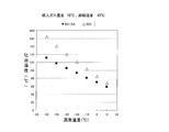
- FIG. 6 is a diagram showing the relationship between the evaporation temperature and the discharge temperature in R32 and R410A when the intake gas temperature sucked into the high temperature side compressor in the intermediate injection cycle shown in FIG. 5 is 18 ° C.
- FIG. 1 is a refrigerant circuit diagram of a refrigeration apparatus according to an embodiment of the present invention.
- a circulation circuit is formed on each of the high temperature side and the low temperature side (load side), and the cascade condenser 9 including the high temperature side evaporator 4 and the low temperature side condenser 6 is shared.
- the high temperature side circulation circuit A is formed by connecting the high temperature side compressor 1, the high temperature side condenser 2, the high temperature side expansion valve 3, and the high temperature side evaporator 4 of the cascade capacitor 9 in series.
- the circulation circuit B is formed by connecting the low temperature side compressor 5, the low temperature side condenser 6 of the cascade condenser 9, the low temperature side expansion valve 7, and the low temperature side evaporator 8 in series.
- the high-temperature side circulation circuit A uses a refrigerant mixture containing 65 wt% or more of R32 or R32 as a refrigerant
- the low-temperature side circulation circuit B uses a refrigerant as a refrigerant. CO2 (carbon dioxide) is used.
- the evaporation temperature of the high-temperature side circulation circuit A is used at a predetermined value (for example, ⁇ 15 ° C.) or more. Further, the degree of superheat may be suppressed to a predetermined value (for example, 10K) or lower, and the evaporation temperature may be used at a predetermined value (for example, ⁇ 30 ° C.) or higher.
- the cascade-type binary refrigeration apparatus configured as described above has a global warming potential (GWP) in the low-temperature side circulation circuit B in which the amount of refrigerant connected to a load-side showcase or unit cooler increases as a measure against global warming. Is used, and the refrigerant R32 having a small global warming potential (GWP) is used in the high-temperature circuit A with a relatively small amount of closed refrigerant.
- GWP global warming potential
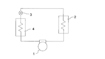
- FIG. 2 is a refrigerant circuit diagram of a single stage cycle
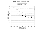
- FIG. 3 is a diagram showing the relationship between the evaporation temperature and the discharge temperature in R32 and R410A when the superheat degree is 10 K in the single stage cycle shown in FIG. is there.
- the refrigerant circuit diagram of the single stage cycle shown in FIG. 2 is a diagram assuming the high temperature side circulation circuit A of the refrigeration apparatus according to the present embodiment.
- FIG. 3 is calculated
- the single-stage cycle is formed by connecting a high temperature side compressor 1, a high temperature side condenser 2, a high temperature side expansion valve 3, and a high temperature side evaporator 4 in series.
- FIG. 3 shows that the refrigerant of R32 or R410A is used in this refrigeration system, the condensation temperature of the high-temperature side condenser 2 is 40 ° C., and the degree of superheat (intake gas temperature of the high-temperature side compressor 1 ⁇ evaporation of the high-temperature side evaporator 4).
- the relationship between the evaporation temperature of the high temperature side evaporator 4 and the discharge temperature of the high temperature side compressor 1 when temperature is 10K is shown.
- the discharge temperature of R32 is higher by about 10 ° C. to 50 ° C. with respect to the same evaporation temperature than R410A, and the difference between the two increases as the evaporation temperature decreases.
- the discharge temperature of the high temperature side compressor 1 needs to be suppressed to 120 ° C. or less from the viewpoint of the reliability of the high temperature side compressor 1 and the refrigerating machine oil. Therefore, R32 may be used at an evaporation temperature of about ⁇ 30 ° C. or higher.
- the discharge temperature exceeds 120 ° C. and becomes high, making it difficult to use.
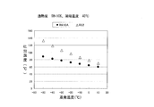
- FIG. 4 is a diagram showing the relationship between the evaporation temperature and the discharge temperature in R32 and R410A when the intake gas temperature drawn into the high-temperature side compressor 1 in the single-stage cycle shown in FIG. 2 is 18 ° C. .
- FIG. 4 shows the case where the refrigerant of R32 or R410A is used in the refrigeration apparatus of FIG. 2, the condensation temperature of the high-temperature side condenser 2 is 40 ° C., and the intake gas temperature drawn into the high-temperature side compressor 1 is 18 ° C.
- the relationship between the evaporation temperature of the high temperature side evaporator 4 and the discharge temperature of the high temperature side compressor 1 is shown.
- the degree of superheat (the intake gas temperature of the high temperature side compressor 1 ⁇ the evaporation temperature of the high temperature side evaporator 4) is 28K.
- the discharge temperature becomes higher, and when the evaporation temperature is -15 ° C. or lower, the discharge temperature exceeds 120 ° C., making it difficult to use.
- the degree of superheat increases at a low evaporation temperature, and the discharge temperature of R32 becomes very high. Therefore, it is necessary to take an appropriate degree of superheat.
- FIG. 5 is a refrigerant circuit diagram of an intermediate injection cycle.
- the refrigerant circuit diagram of the intermediate injection cycle shown in FIG. 5 is a diagram assuming the high temperature side circulation circuit A of the refrigeration apparatus according to the present embodiment.
- a method of suppressing the discharge temperature there is a method of injecting a refrigerant cooled while the high temperature side compressor 1 is compressed as, for example, a scroll type or a rotary type.
- FIG. 5 is a refrigerant circuit diagram of the intermediate injection cycle. Indicates. In the intermediate injection cycle, a high temperature side compressor 1, a high temperature side condenser 2, a high temperature side expansion valve 3, and a high temperature side evaporator 4 are connected in series.
- the liquid receiver 11 is provided in the exit of the high temperature side condenser 2
- the supercooling heat exchanger 12 is provided between the liquid receiver 11 and the high temperature side expansion valve 3
- the supercooling heat exchanger 12 and the high temperature side expansion are provided.
- a refrigerant pipe 12b branched from the valve 3 is provided with an expansion valve 13 for the supercooling heat exchanger.
- the refrigerant pipe 12b expanded and cooled by the expansion valve 13 for the supercooling heat exchanger, and the liquid discharged from the liquid receiver 11
- FIG. 6 is a diagram showing the relationship between the evaporation temperature and the discharge temperature in R32 and R410A when the superheat degree is 10K in the intermediate injection cycle shown in FIG.
- FIG. 6 shows that the refrigerant of R32 or R410A is used in a refrigeration apparatus that employs an intermediate injection cycle, the condensation temperature of the high-temperature side condenser 2 is 40 ° C., and the degree of superheat (high-temperature side compressor 1 intake gas temperature ⁇ high-temperature side)
- the relationship between the evaporation temperature of the high temperature side evaporator 4 and the discharge temperature of the high temperature side compressor 1 when the evaporation temperature of the evaporator 4 is 10K is shown. As shown in FIG.
- the discharge temperature at R32 is improved by about 20 ° C. and lowered by the intermediate injection.
- the discharge temperature of the high temperature side compressor 1 needs to be suppressed to 120 ° C. or less from the viewpoint of the reliability of the high temperature side compressor 1 and the refrigerating machine oil. Therefore, R32 may be used at an evaporation temperature of about ⁇ 40 ° C. or higher.
- the discharge temperature exceeds 120 ° C. and becomes high, making it difficult to use.
- R32 may be used for the high-temperature side circulation circuit A and CO2 may be used for the low-temperature side circulation circuit B.
- FIG. 7 is a diagram showing the relationship between the evaporation temperature and the discharge temperature in R32 and R410A when the intake gas temperature sucked into the high temperature side compressor 1 in the intermediate injection cycle shown in FIG. 5 is 18 ° C. .
- FIG. 7 shows a case where the refrigerant of R32 or R410A is used in the refrigeration apparatus of FIG. 5, the condensation temperature of the high temperature side condenser 2 is 40 ° C., and the intake gas temperature sucked into the high temperature side compressor 1 is 18 ° C.
- the relationship between the evaporation temperature of the high temperature side evaporator 4 and the discharge temperature of the high temperature side compressor 1 is shown.
- the degree of superheat (intake gas temperature of the high temperature side compressor 1 ⁇ evaporation temperature of the high temperature side evaporator 4) is 28K.
- the discharge temperature is higher than in the above case, and when the evaporation temperature is ⁇ 20 ° C. or lower, the discharge temperature exceeds 120 ° C., making it difficult to use.
- the degree of superheat increases, and even if an intermediate injection cycle is adopted, the discharge temperature of R32 becomes very high. Therefore, by adopting an intermediate injection circuit in the high-temperature side circulation circuit A and suppressing the degree of superheat to 10K or less, the evaporation temperature may be used at about ⁇ 40 ° C. or more as shown in FIG.
- the COP (coefficient of performance) when the evaporation temperature is ⁇ 10 ° C. and ⁇ 40 ° C. in a single-stage cycle when the refrigerant of R410A is used is about 2.2 and 0.96 as calculated values, respectively.
- the COP (coefficient of performance) when the R32 refrigerant is used for the high-temperature side circulation circuit and the CO2 refrigerant is used for the low-temperature side circulation circuit is almost equal to that of the single-stage cycle when the R410A refrigerant is used. It is clear from the calculation results that they are equivalent or better.
- the high-temperature side circulation circuit A uses R32 or a mixed refrigerant containing 65% by weight or more of R32 as the refrigerant
- the low-temperature side circulation circuit B uses CO2 (carbon dioxide) as the refrigerant.
- the evaporation temperature of the high-temperature side circulation circuit A is used at a predetermined value (for example, ⁇ 15 ° C.) or more.
- the degree of superheat is 10K or less and the evaporation temperature is used at -30 ° C or higher, the reliability of the compressor is not lowered, the performance is not lowered, and energy saving and low environmental load (low global warming potential) are achieved. (GWP)) can be realized.
- CO2 refrigerant is used in the part where the refrigerant amount in the low-temperature side circulation circuit is large, and R32 refrigerant is used in the relatively closed refrigerant circuit in the high-temperature side circulation circuit A. Therefore, the global warming potential (GWP) as a system is It can be reduced to about 1/3 of the R32 independent global warming potential (GWP) 675.
- an intermediate injection circuit is used for the high-temperature side circulation circuit A, it can be used at an evaporation temperature of -40 ° C or higher by limiting the superheat to 10K or lower, without reducing the compressor reliability and performance.
- energy saving and low environmental load can be realized.
Landscapes
- Engineering & Computer Science (AREA)
- Physics & Mathematics (AREA)
- Mechanical Engineering (AREA)
- Thermal Sciences (AREA)
- General Engineering & Computer Science (AREA)
- Air Conditioning Control Device (AREA)
Abstract
Dispositif frigorifique comportant: un circuit (A) de circulation à haute température dans lequel circule un agent frigorigène et qui comprend un compresseur (1) à haute température, un condenseur (2) à haute température, un détendeur (3) à haute température et un évaporateur (4) à haute température d'un condenseur (9) en cascade, reliés en série par des canalisations; et un circuit (B) de circulation à basse température dans lequel circule un agent frigorigène et qui comprend un compresseur (5) à basse température, un condenseur (6) à basse température du condenseur (9) en cascade, un détendeur (7) à basse température et un évaporateur (8) à basse température, reliés en série par des canalisations. Du R32 ou un mélange d'agents frigorigènes contenant au moins 65% en masse de R32 est utilisé en tant qu'agent frigorigène pour le circuit (A) de circulation à haute température, du CO2 est utilisé en tant qu'agent frigorigène pour le circuit (B) de circulation à basse température, et la température d'évaporation pour le circuit (A) de circulation à haute température est réglée de façon à être supérieure ou égale à −15°C.
Priority Applications (2)
| Application Number | Priority Date | Filing Date | Title |
|---|---|---|---|
| PCT/JP2013/066104 WO2014199445A1 (fr) | 2013-06-11 | 2013-06-11 | Dispositif frigorifique |
| JP2015522293A JPWO2014199445A1 (ja) | 2013-06-11 | 2013-06-11 | 冷凍装置 |
Applications Claiming Priority (1)
| Application Number | Priority Date | Filing Date | Title |
|---|---|---|---|
| PCT/JP2013/066104 WO2014199445A1 (fr) | 2013-06-11 | 2013-06-11 | Dispositif frigorifique |
Publications (1)
| Publication Number | Publication Date |
|---|---|
| WO2014199445A1 true WO2014199445A1 (fr) | 2014-12-18 |
Family
ID=52021781
Family Applications (1)
| Application Number | Title | Priority Date | Filing Date |
|---|---|---|---|
| PCT/JP2013/066104 Ceased WO2014199445A1 (fr) | 2013-06-11 | 2013-06-11 | Dispositif frigorifique |
Country Status (2)
| Country | Link |
|---|---|
| JP (1) | JPWO2014199445A1 (fr) |
| WO (1) | WO2014199445A1 (fr) |
Cited By (5)
| Publication number | Priority date | Publication date | Assignee | Title |
|---|---|---|---|---|
| EP3187796A1 (fr) * | 2015-12-28 | 2017-07-05 | Thermo King Corporation | Système de transfert thermique en cascade |
| WO2017138058A1 (fr) * | 2016-02-08 | 2017-08-17 | 三菱電機株式会社 | Dispositif frigorifique |
| CN111735224A (zh) * | 2020-01-21 | 2020-10-02 | 天津冷源工程设计院 | 一种适用于多种负荷工况的制冷系统 |
| CN116123747A (zh) * | 2023-04-14 | 2023-05-16 | 云南道精制冷科技有限责任公司 | 一种复叠式冷热源机组 |
| CN120466860A (zh) * | 2025-06-19 | 2025-08-12 | 江苏拓米洛高端装备股份有限公司 | 一种制冷系统和环境试验箱 |
Citations (7)
| Publication number | Priority date | Publication date | Assignee | Title |
|---|---|---|---|---|
| JPH10197078A (ja) * | 1996-12-27 | 1998-07-31 | Kobe Steel Ltd | 冷凍回路 |
| JP2005180866A (ja) * | 2003-12-22 | 2005-07-07 | Sanyo Electric Co Ltd | 二元冷凍装置 |
| JP2010223542A (ja) * | 2009-03-25 | 2010-10-07 | Mitsubishi Electric Corp | 冷凍空調装置 |
| WO2012066763A1 (fr) * | 2010-11-15 | 2012-05-24 | 三菱電機株式会社 | Congélateur |
| JP2012112617A (ja) * | 2010-11-26 | 2012-06-14 | Mitsubishi Electric Corp | 冷凍装置 |
| JP2012193908A (ja) * | 2011-03-17 | 2012-10-11 | Toshiba Carrier Corp | 二元冷凍サイクル装置 |
| JP2013510286A (ja) * | 2009-11-03 | 2013-03-21 | イー・アイ・デュポン・ドウ・ヌムール・アンド・カンパニー | フルオロオレフィン冷媒を用いるカスケード冷凍システム |
-
2013
- 2013-06-11 WO PCT/JP2013/066104 patent/WO2014199445A1/fr not_active Ceased
- 2013-06-11 JP JP2015522293A patent/JPWO2014199445A1/ja active Pending
Patent Citations (7)
| Publication number | Priority date | Publication date | Assignee | Title |
|---|---|---|---|---|
| JPH10197078A (ja) * | 1996-12-27 | 1998-07-31 | Kobe Steel Ltd | 冷凍回路 |
| JP2005180866A (ja) * | 2003-12-22 | 2005-07-07 | Sanyo Electric Co Ltd | 二元冷凍装置 |
| JP2010223542A (ja) * | 2009-03-25 | 2010-10-07 | Mitsubishi Electric Corp | 冷凍空調装置 |
| JP2013510286A (ja) * | 2009-11-03 | 2013-03-21 | イー・アイ・デュポン・ドウ・ヌムール・アンド・カンパニー | フルオロオレフィン冷媒を用いるカスケード冷凍システム |
| WO2012066763A1 (fr) * | 2010-11-15 | 2012-05-24 | 三菱電機株式会社 | Congélateur |
| JP2012112617A (ja) * | 2010-11-26 | 2012-06-14 | Mitsubishi Electric Corp | 冷凍装置 |
| JP2012193908A (ja) * | 2011-03-17 | 2012-10-11 | Toshiba Carrier Corp | 二元冷凍サイクル装置 |
Cited By (11)
| Publication number | Priority date | Publication date | Assignee | Title |
|---|---|---|---|---|
| EP3187796A1 (fr) * | 2015-12-28 | 2017-07-05 | Thermo King Corporation | Système de transfert thermique en cascade |
| US10543737B2 (en) | 2015-12-28 | 2020-01-28 | Thermo King Corporation | Cascade heat transfer system |
| US11351842B2 (en) | 2015-12-28 | 2022-06-07 | Thermo King Corporation | Cascade heat transfer system |
| WO2017138058A1 (fr) * | 2016-02-08 | 2017-08-17 | 三菱電機株式会社 | Dispositif frigorifique |
| JPWO2017138058A1 (ja) * | 2016-02-08 | 2018-09-06 | 三菱電機株式会社 | 冷凍装置及び冷凍装置の制御装置 |
| GB2562639A (en) * | 2016-02-08 | 2018-11-21 | Mitsubishi Electric Corp | Refrigeration device |
| US10845108B2 (en) | 2016-02-08 | 2020-11-24 | Mitsubishi Electric Corporation | Refrigeration device and controller for refrigeration device |
| GB2562639B (en) * | 2016-02-08 | 2021-02-17 | Mitsubishi Electric Corp | Refrigeration device and controller for refrigeration device |
| CN111735224A (zh) * | 2020-01-21 | 2020-10-02 | 天津冷源工程设计院 | 一种适用于多种负荷工况的制冷系统 |
| CN116123747A (zh) * | 2023-04-14 | 2023-05-16 | 云南道精制冷科技有限责任公司 | 一种复叠式冷热源机组 |
| CN120466860A (zh) * | 2025-06-19 | 2025-08-12 | 江苏拓米洛高端装备股份有限公司 | 一种制冷系统和环境试验箱 |
Also Published As
| Publication number | Publication date |
|---|---|
| JPWO2014199445A1 (ja) | 2017-02-23 |
Similar Documents
| Publication | Publication Date | Title |
|---|---|---|
| US10254016B2 (en) | Refrigeration cycle apparatus and method for controlling refrigeration cycle apparatus | |
| US10101060B2 (en) | Cooling system | |
| JP5995990B2 (ja) | 冷凍装置 | |
| EP3070417A1 (fr) | Système de réfrigération | |
| JPWO2014030236A1 (ja) | 冷凍装置 | |
| US20230135967A1 (en) | Refrigeration device | |
| JP6188918B2 (ja) | 冷凍装置 | |
| CN103808068A (zh) | 一种制冷系统 | |
| US20190137147A1 (en) | Refrigeration systems and methods | |
| JP7189423B2 (ja) | 冷凍サイクル装置 | |
| WO2014199445A1 (fr) | Dispositif frigorifique | |
| CN203824153U (zh) | 制冷循环装置 | |
| TWI564524B (zh) | Refrigeration cycle | |
| JP2008164288A (ja) | 冷凍装置 | |
| EP3642541B1 (fr) | Système de réfrigération en cascade | |
| JP6765086B2 (ja) | 冷凍装置 | |
| JP2005180866A (ja) | 二元冷凍装置 | |
| JP6393181B2 (ja) | 冷凍サイクル装置 | |
| JP2007263488A (ja) | 冷凍装置 | |
| JP2008164287A (ja) | 冷凍装置 | |
| JP6372778B2 (ja) | 冷凍装置 | |
| KR102446555B1 (ko) | 심온 냉동고 | |
| KR102153341B1 (ko) | 공기조화기 | |
| JP2015129609A (ja) | 冷凍装置 | |
| JPWO2015140875A1 (ja) | 冷凍装置 |
Legal Events
| Date | Code | Title | Description |
|---|---|---|---|
| 121 | Ep: the epo has been informed by wipo that ep was designated in this application |
Ref document number: 13886725 Country of ref document: EP Kind code of ref document: A1 |
|
| ENP | Entry into the national phase |
Ref document number: 2015522293 Country of ref document: JP Kind code of ref document: A |
|
| NENP | Non-entry into the national phase |
Ref country code: DE |
|
| 122 | Ep: pct application non-entry in european phase |
Ref document number: 13886725 Country of ref document: EP Kind code of ref document: A1 |