WO2014199466A1 - Moteur électrique à aimant permanant intégré, et compresseur - Google Patents
Moteur électrique à aimant permanant intégré, et compresseur Download PDFInfo
- Publication number
- WO2014199466A1 WO2014199466A1 PCT/JP2013/066232 JP2013066232W WO2014199466A1 WO 2014199466 A1 WO2014199466 A1 WO 2014199466A1 JP 2013066232 W JP2013066232 W JP 2013066232W WO 2014199466 A1 WO2014199466 A1 WO 2014199466A1
- Authority
- WO
- WIPO (PCT)
- Prior art keywords
- permanent magnet
- electric motor
- magnet
- depressions
- slits
- Prior art date
- Legal status (The legal status is an assumption and is not a legal conclusion. Google has not performed a legal analysis and makes no representation as to the accuracy of the status listed.)
- Ceased
Links
Images





Classifications
-
- H—ELECTRICITY
- H02—GENERATION; CONVERSION OR DISTRIBUTION OF ELECTRIC POWER
- H02K—DYNAMO-ELECTRIC MACHINES
- H02K1/00—Details of the magnetic circuit
- H02K1/06—Details of the magnetic circuit characterised by the shape, form or construction
- H02K1/22—Rotating parts of the magnetic circuit
- H02K1/27—Rotor cores with permanent magnets
- H02K1/2706—Inner rotors
- H02K1/272—Inner rotors the magnetisation axis of the magnets being perpendicular to the rotor axis
- H02K1/274—Inner rotors the magnetisation axis of the magnets being perpendicular to the rotor axis the rotor consisting of two or more circumferentially positioned magnets
- H02K1/2753—Inner rotors the magnetisation axis of the magnets being perpendicular to the rotor axis the rotor consisting of two or more circumferentially positioned magnets the rotor consisting of magnets or groups of magnets arranged with alternating polarity
- H02K1/276—Magnets embedded in the magnetic core, e.g. interior permanent magnets [IPM]
-
- H—ELECTRICITY
- H02—GENERATION; CONVERSION OR DISTRIBUTION OF ELECTRIC POWER
- H02K—DYNAMO-ELECTRIC MACHINES
- H02K1/00—Details of the magnetic circuit
- H02K1/02—Details of the magnetic circuit characterised by the magnetic material
-
- H—ELECTRICITY
- H02—GENERATION; CONVERSION OR DISTRIBUTION OF ELECTRIC POWER
- H02K—DYNAMO-ELECTRIC MACHINES
- H02K2213/00—Specific aspects, not otherwise provided for and not covered by codes H02K2201/00 - H02K2211/00
- H02K2213/03—Machines characterised by numerical values, ranges, mathematical expressions or similar information
Definitions
- the present invention relates to a permanent magnet embedded electric motor in which a permanent magnet is embedded in a rotor core, and a compressor including the same.
- a permanent magnet embedded type motor in which a permanent magnet is embedded in a rotor core is often used.
- a plurality of magnet housing holes for embedding a plurality of permanent magnets are provided inside the rotor core.
- a slit extending in the radial direction is provided in the outer core portion of the permanent magnet.
- the rotor of the embedded permanent magnet electric motor disclosed in FIG. 2 of Patent Document 1 has a plurality of slits in the vicinity of the outer peripheral portion of the iron core of the permanent magnet.
- Dy dysprosium
- the compressor disclosed in Patent Document 2 is provided with a brushless DC motor and a compressor body concentrically inside a hermetic casing, and as a refrigerant that is sucked, compressed, and discharged by the compressor body, R32 simple substance or R32 rich mixed refrigerant was adopted, and the J coercivity of the rare earth magnet was set to 23 kOe or more.
- JP 2008-022601 A (mainly see FIG. 2) JP 2001-115963 A (mainly see FIG. 12)
- the embedded permanent magnet electric motor shown in Patent Document 1 has a magnet when a demagnetizing field (magnetic flux reverse to the magnetic flux generated by the permanent magnet) generated by the stator winding is applied to the rotor. Since the magnetic permeability of the magnetic flux is almost the same as that of air and the magnetic flux does not easily pass, the magnetic flux tends to flow in the direction in which the magnetic resistance is small. At this time, the demagnetizing field tries to pass through the iron core portion between the magnet housing hole having the smallest magnetic resistance and the plurality of slits. However, since the iron core portion is thin, the iron core portion is magnetically saturated, and the plurality of slits. And pass along the surface of the magnet facing. Thereby, the demagnetizing field was added to the surface of the magnet, and the subject that the surface of the magnet demagnetized had the subject.
- a demagnetizing field magnetic flux reverse to the magnetic flux generated by the permanent magnet
- the present invention has been made in view of the above, and improves the demagnetization resistance of the surface of the magnet without depending on the demagnetization preventing action by the contained material while suppressing the electromagnetic excitation force generated in the electric motor.
- An object of the present invention is to provide an embedded permanent magnet electric motor.
- the present invention provides a rotor, a stator installed so as to face the rotor with a gap, and a plurality of magnets formed in the rotor core of the rotor.
- a permanent magnet embedded type electric motor comprising a plurality of permanent magnets inserted into the respective holes and a plurality of slits formed on the rotor core of the rotor on the radially outer side of the magnet housing holes.
- a space is secured for each region where the plurality of slits face between the radially outer surface of each of the plurality of permanent magnets and the rotor core. The surface is separated from the rotor core through the space portion for each region where the plurality of slits face each other.
- the present invention it is possible to improve the demagnetization resistance of the surface of the magnet without depending on the demagnetization preventing action by the contained material while suppressing the electromagnetic excitation force generated in the electric motor.
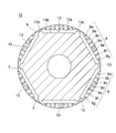
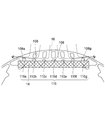
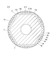
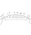
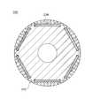
- FIG. 2 It is sectional drawing of the permanent magnet embedded type electric motor which concerns on Embodiment 1 of this invention. It is sectional drawing of the rotor core shown by FIG. It is the elements on larger scale for 1 pole of the rotor core shown by FIG. It is a figure which shows the rotor of the state which accommodated the rare earth magnet in the rotor core of FIG. It is a conceptual diagram which shows the flow of the magnetic flux by a demagnetizing field. It is sectional drawing which shows the modification of the rotor of FIG. It is a figure of the same aspect as FIG. 2 regarding Embodiment 2 of this invention. It is a figure of the same aspect as FIG. 3 regarding this Embodiment 2. FIG. It is a figure of the same aspect as FIG.
- FIG. It is a figure of the same aspect as FIG. 5 regarding this Embodiment 2.
- FIG. It is a figure of the same aspect as FIG. 5 regarding this Embodiment 3.
- FIG. It is a longitudinal cross-sectional view of the rotary compressor which mounts a permanent magnet embedded electric motor regarding Embodiment 4 of this invention.
- FIG. 1 is a cross-sectional view of a permanent magnet embedded electric motor according to Embodiment 1 of the present invention
- FIG. 2 is a cross-sectional view showing a rotor core shown in FIG. 1
- FIG. FIG. 4 is a diagram showing a rotor in a state where an Nd / Fe / B rare earth magnet is accommodated in the rotor core of FIG.
- a plane whose perpendicular line is a rotation axis of a rotor described later is a paper surface.
- an embedded permanent magnet electric motor 50 includes an annular stator 1 and a rotor 100.
- the stator 1 includes an annular stator core 2 and a circumferential direction in the inner peripheral portion of the stator core 2 (circumferential direction around the rotation axis in a plane perpendicular to the rotation axis of the rotor, A plurality of slots 3 formed at equiangular pitches in the direction of the rotation trajectory of the rotor 100 and coils 4 accommodated in the slots 3 are provided.
- a rotor 100 is rotatably disposed on the inner peripheral side of the stator 1, and a cylinder is provided between the outer peripheral surface 15 of the rotor 100 (rotor core 12) and the inner peripheral surface 1 a of the stator 1.
- a void 5 is formed.
- the stator 1 shown in FIG. 1 is a distributed winding stator as an example, but may be a concentrated winding stator.
- the rotor 100 has a rotating shaft 11, a rotor core 12, and a plurality of permanent magnets 14 as main components. Rotational energy from the drive source is transmitted to the rotary shaft 11, and the rotor core 12 provided around the rotary shaft 11 is rotated by the rotational energy.
- the rotor core 12 and the rotating shaft 11 are connected by, for example, shrink fitting and press fitting.
- the rotor core 12 is manufactured by laminating a plurality of silicon steel plates (component plates) punched into a predetermined shape with a mold in the direction in which the rotation shaft 11 extends (the front and back direction in FIG. 2).
- the outer peripheral surface 15 of the rotor core 12 is formed in a cylindrical shape.
- the rotor core 12 has six magnet housing holes 13 arranged along the circumferential direction.
- the six magnet housing holes 13 have the same shape.
- Each of the six magnet accommodation holes 13 extends over an equal angular range, and the radial positions of the respective portions of the magnet accommodation holes 13 are the same in the six magnet accommodation holes 13.
- Each of the magnet housing holes 13 has an outer demarcation line 13a and an inner demarcation line 13b in the radial direction (the direction of the radius about the rotation axis in the plane having the rotation axis of the rotor as a perpendicular) in the plane of FIG. And a pair of end lines 13c.
- the pair of end lines 13c connects the end 13d (see FIG. 3) of the outer demarcation line 13a and the end 13e (see FIG. 3) of the inner demarcation line 13b in the vicinity of the outer peripheral surface 15 of the rotor core 12. Yes.
- Most of the outer demarcating line 13a and the inner demarcating line 13b (excluding the ends) extend in a direction perpendicular to the radial direction.
- the rotor core 12 includes an outer peripheral thin core 6 between the outer peripheral surface 15 of the rotor core 12 and each end line 13c of each magnet housing hole 13.
- the rotor core 12 By configuring the rotor core 12 in this way, the magnetic resistance in the vicinity of both end portions (end lines 13c) of the magnet housing hole 13 can be increased. Thereby, the short circuit magnetic flux of a magnet can be reduced and high torque can be realized.
- the outer demarcation line 13a of the magnet housing hole 13 is provided with a plurality of depressions 8 (8a to 8g) that protrude toward the outer peripheral surface 15 side. These hollow portions 8 are arranged at positions facing slits 9 (9a to 9g) described later. In the first embodiment, one recess 8 is provided corresponding to one slit 9, that is, the same number of recesses 8 as the slits 9 are provided.
- the distance between the outer demarcating line 13a and each of the plurality of slits 9 is substantially the same through one pole, and the radial depths of the plurality of recesses 8 are also substantially the same through one pole.
- the depth dimension of the hollow portion 8 is sufficiently smaller than the radial thickness dimension of the permanent magnet 14, and in this embodiment, the depth dimension is 0.6 mm with respect to the magnet thickness dimension of 2 mm.
- the depth of a hollow part is not limited to this, It is suitable if it is 1/3 or less with respect to the thickness dimension of the radial direction of a magnet.
- the opening portion (the convex base portion referred to as the above-mentioned convexity) connected to the outer demarcating line 13 a is the largest, and the width dimension is substantially the same as the width dimension of the slit 9 described later. Are equal.
- a pair of protrusions 7 are formed at both ends of the inner demarcation line 13b of each of the magnet accommodation holes 13.
- a pair of projection part 7 protrudes toward a radial direction outer side.
- the height of the protrusion 7 is secured such that when the permanent magnet 14 is inserted, the end face 14a (see FIG. 4) in the longitudinal direction of the permanent magnet 14 and the side surface 7a of the protrusion 7 can be in surface contact. .
- the surface contact portion only needs to have a dimension that can prevent displacement of the permanent magnet 14 at the lower limit of the dimensional tolerance of the permanent magnet 14. In this example, it is about 0.5 mm.
- a plurality of (seven) slits 9 (9a to 9g) are arranged in the core portion between the magnet housing hole 13 and the outer peripheral surface 15 in the rotor core 12.
- the slit 9 (9a to 9g) has no opening connected to the magnet housing hole 13 and the outer peripheral surface 15, and has a closed shape inside the rotor core 12.
- the plurality of slits 9 extend substantially in the radial direction, and the slit 9d at the central part of the magnetic pole is the longest in terms of the length extending in the substantially radial direction, and approaches the inter-polar part. The length decreases, and the slits 9a and 9g at the inter-electrode portions are the shortest.
- thin outer core portions 17 (17 a to 17 g) are formed between each of the plurality of slits 9 and the outer peripheral surface 15.
- a thin inner core portion is provided between the plurality of slits 9 (9a to 9g) and the recessed portions 8 (8a to 8g) arranged to face the slits 9 (9a to 9g). 18 (18a to 18g) are formed.
- each of the plurality of outer iron core portions 17 and the plurality of inner iron core portions 18 is configured to be approximately the thickness of the electromagnetic steel sheet. For example, it is about 0.2 mm to 0.5 mm.
- the magnetic flux generated by the windings of the stator 1 does not pass through the surface of the permanent magnet 14, but the inner iron core portion 18 (18a to 18g).
- the inner iron core portion 18 Even when the inner iron core is magnetically saturated, the magnetic flux generated by the windings of the stator 1 passes through the space in the depression 8 (8a to 8g), and therefore the demagnetization of the outer peripheral surface of the permanent magnet 14 is achieved. Yield can be improved.
- FIGS. 4 and 5 show a state where the rare earth magnet is accommodated in the rotor core of FIG.
- a corresponding permanent magnet 14 is accommodated in each of the magnet accommodation holes 13. That is, the permanent magnets 14 constituting the magnetic poles of the rotor core 12 are arranged in the circumferential direction of the rotor core 12 by the same number as the number of poles, and are magnetized so that N poles and S poles are alternated.
- the plurality of recesses 8 are formed between the plurality of inner iron core portions 18 and the radially outer surface 14b of the permanent magnet 14.
- a plurality of space portions 10 (10a to 10g) secured by the existence are formed.
- the space portion 10 is secured between the radially outer surface 14b of each of the plurality of permanent magnets 14 and the rotor core 12 for each region where the plurality of slits 9 are opposed to each other.
- the surface 14 b of the magnet 14 is separated from the rotor core 12 via the space 10 for each region where the plurality of slits 9 face each other.
- the portion of the surface 14b on the outer side in the radial direction of the permanent magnet 14 at the position facing the slit 9 does not come into contact with the portion of the rotor core 12 (outer defining line 13a), and the corresponding space portion 10 is formed. It faces the rotor core 12 with a gap.
- the permanent magnet 14 is an Nd / Fe / B rare earth magnet having a residual magnetic flux density of 1.2 T or more at room temperature and a J coercivity of less than 23 kOe at room temperature.
- the shape of the magnet is a flat plate shape, and the permanent magnet 14 is disposed so as to be sandwiched between the pair of protrusions 7.
- the magnetic flux 16 is between the slits 9 in the rotor core 12, as shown in FIG. , Passing through the outer peripheral thin core 6 through the inner core 18 and the recess 8 (space 10), avoiding the radially outer surface of the permanent magnet 14.
- the demagnetizing field generated by the stator winding while suppressing the electromagnetic excitation force generated in the electric motor by the plurality of slits can be prevented from passing through the surface on the radially outer side of the permanent magnet, the demagnetization of the surface portion of the permanent magnet can be suppressed, and an electric motor with less torque reduction can be provided. Moreover, since the suppression of demagnetization of the surface portion of the permanent magnet is realized without relying on the demagnetization preventing action by the material containing the permanent magnet, the amount of Dy contained in the rare earth magnet can be reduced and the cost can be reduced. Can also be obtained.
- the residual magnetic flux density of the magnet is increased, and the torque can be increased. That is, according to the first embodiment, it is possible to achieve both suppression of electromagnetic excitation force and suppression of demagnetization of the surface portion of the permanent magnet while promoting both cost reduction and torque increase. , Very good advantages.
- the refrigerant flows through the space provided in the recess so that the temperature of the permanent magnet can be reduced and the demagnetization resistance can be improved.
- the depth dimensions of the plurality of depressions are all the same.
- the first embodiment is not limited to this.
- a plurality of slits 109 and a plurality of depressions 108 are provided at a position facing at least the slits 109, and the depressions 108 are provided.
- These recesses are formed so that the depth dimension is smaller (shallow) closer to the center part of the magnetic pole, and the depth dimension is larger (deeper) closer to the gap part. Also good. In this case, as shown in FIG.
- no slits may be disposed at the positions where the recesses 108a and the recesses 108g at both ends (near the gap) face each other. There may be a very small slit at a position facing the depression near the portion.
- the modified form using the plurality of depressions having different depth dimensions also reduces the concentration of the magnetic flux on both ends of the permanent magnet. Thus, the effect of improving the demagnetization resistance at both ends of the permanent magnet can be obtained.
- FIGS. 7, FIG. 8, FIG. 9 and FIG. 10 are diagrams related to the second embodiment, respectively, in the same manner as FIG.
- the second embodiment is the same as the first embodiment described above except for the parts described below.
- a space is secured for each region facing the plurality of slits between the radially outer surface of each of the plurality of permanent magnets and the rotor core.
- these spaces are secured by a plurality of recesses provided in the outer demarcation line of the magnet accommodation hole.
- the spaces are provided on the radially outer surface of the permanent magnet. It is ensured by a plurality of depressions.
- the rotor 200 according to Embodiment 2 includes a rotor core 212 having a plurality of magnet housing holes 213.
- the outer demarcating line 213a in each of the magnet accommodation holes 213 extends in a planar shape in a direction perpendicular to the radial direction except for the end portions, that is, the outer demarcating line 213a corresponds to the recess 8 in the first embodiment.
- the concave part to be formed is not formed.
- a plurality of dents 208 that are convex toward the inner demarcating line 13b are provided on the radially outer surface 214b of the permanent magnet 214 facing each of the outer demarcating lines 213a.
- the depth and width dimension of these hollow parts 208 shall be the same aspect as the dimension of the hollow part described in Embodiment 1.
- the same advantages as those of the first embodiment can be obtained, and the demagnetization preventing action by the contained material can be suppressed while suppressing the electromagnetic excitation force generated in the electric motor.
- the demagnetization resistance of the surface of the magnet can be improved without relying on it.
- FIG. 11 is a diagram of the same mode as FIG.
- the third embodiment is also the same as the above-described first embodiment except for the parts described below.
- the rotor 300 according to the third embodiment is provided with both the recess 8 in the first embodiment and the recess 208 in the second embodiment. That is, a plurality of depressions 8 are provided in the outer demarcation line 13 a of the magnet housing hole 13 of the rotor 300, and a plurality of depressions are formed on the radially outer surface 214 b of the permanent magnet 214 of the rotor 300. 208 is provided.
- the plurality of space portions 310 secured for each region where the plurality of slits 9 are opposed to each other are a space in which the hollow portion 8 of the rotor core 12 and the hollow portion 208 of the permanent magnet 214 are combined. It is secured by the depressions 8 and 208.
- Embodiment 3 also provides the same advantages as those of Embodiment 1 described above, and suppresses the electromagnetic excitation force generated in the electric motor, but does not rely on the demagnetization preventing action by the contained material, but the surface of the magnet Can improve the demagnetization resistance.
- a permanent magnet embedded synchronous motor that can easily and efficiently secure a larger space for each opposed region of the plurality of slits 9 and further improve the demagnetization resistance of the permanent magnet surface portion. Obtainable.
- Embodiment 4 FIG. Next, as Embodiment 4 of the present invention, a rotary compressor on which the permanent magnet embedded type electric motor of any of Embodiments 1 to 3 described above is mounted will be described.
- the present invention includes a compressor including the permanent magnet embedded electric motor according to any of the first to third embodiments described above, but the type of the compressor is not limited to the rotary compressor. .
- FIG. 12 is a longitudinal sectional view of a rotary compressor equipped with a permanent magnet embedded type electric motor.
- the rotary compressor 150 includes a permanent magnet embedded electric motor 50 (electric element) and a compression element 30 in the hermetic container 25.
- refrigerating machine oil that lubricates each sliding portion of the compression element 30 is stored at the bottom of the sealed container 25.
- the compression element 30 includes, as main elements, a cylinder 20 provided in a vertically stacked state, a rotating shaft 11 that is rotated by an electric motor, a piston 21 that is inserted into the rotating shaft 11, and a suction side and a compression side inside the cylinder 20. And a pair of upper and lower frames 22a and 22b, and a pair of upper and lower frames 22a and 22b, which are rotatably inserted into the vane (not shown) and close the axial end surface of the cylinder 20, respectively. Each includes a muffler 24a and 24b mounted.
- the stator 1 of the embedded permanent magnet motor 50 is directly attached and held in the sealed container 25 by a method such as shrink fitting or welding. Electric power is supplied to the coil 4 of the stator 1 from a glass terminal 26 fixed to the hermetic container 25.
- the rotor 100 is disposed via a gap provided on the inner diameter side of the stator 1, and is a bearing for the compression element 30 provided at the lower portion of the rotary compressor 150 via the rotary shaft 11 at the center of the rotor 100. It is held in a freely rotatable state by the parts (upper frame 22a and lower frame 22b).
- the refrigerant gas supplied from the accumulator 41 is sucked into the cylinder 20 through the suction pipe 28 fixed to the sealed container 25.
- the permanent magnet embedded electric motor 50 is rotated by energization of the inverter, whereby the piston 21 fitted to the rotating shaft 11 is rotated in the cylinder 20.
- the refrigerant is compressed in the cylinder 20.
- the compressed high-temperature refrigerant passes through the mufflers 24 a and 24 b, and then rises in the sealed container 25 through the air holes of the permanent magnet embedded electric motor 50. In this way, the compressed refrigerant is supplied to the high-pressure side of the refrigeration cycle through the discharge pipe 29 provided in the sealed container 25.
- refrigerants such as R410A, R407C, and R22 are used as the refrigerant of the rotary compressor 150, but any refrigerant such as a low GWP (global warming potential) refrigerant can be applied. From the viewpoint of preventing global warming, a low GWP refrigerant is desired. As typical examples of the low GWP refrigerant, there are the following refrigerants.
- HFO is an abbreviation for Hydro-Fluoro-Olefin
- Olefin is an unsaturated hydrocarbon having one double bond.
- the GFO of HFO-1234yf is 4.
- Hydrocarbon having a carbon double bond in the composition for example, R1270 (propylene).
- GWP is 3, which is smaller than HFO-1234yf, but flammability is larger than HFO-1234yf.
- a mixture containing at least one of a halogenated hydrocarbon having a carbon double bond in the composition or a hydrocarbon having a carbon double bond in the composition for example, a mixture of HFO-1234yf and R32 is there. Since HFO-1234yf is a low-pressure refrigerant, its pressure loss is large, and the performance of the refrigeration cycle (especially in an evaporator) tends to deteriorate. Therefore, a mixture with R32 or R41, which is a high-pressure refrigerant, is more effective than HFO-1234yf in practical use.
- R32 refrigerant is notable for toxicity and is not highly flammable, and thus has received particular attention. Further, when the R32 refrigerant is used for the rotary compressor 150, the internal temperature of the rotary compressor 150 is higher by about 20 ° C. or more than R410A, R407C, R22 and the like conventionally used.
- the temperature inside the rotary compressor 150 varies depending on the compression load state (rotation speed, compression load torque, refrigerant), and in the steady state where the temperature is stable, the dependence on the rotation speed is particularly high.
- the temperature rise inside the rotary compressor with respect to the rotational speed when using R410 refrigerant is 70 to 80 ° C. for medium speed operation and 90 to 110 ° C. for high speed operation, compared to 50 to 60 ° C. for low speed operation.
- the internal temperature of the rotary compressor 150 increases.
- the temperature in the rotary compressor 150 further increases by about 20 ° C. with respect to the R410A refrigerant.
- the rotary compressor constructed as described above uses a permanent magnet embedded type electric motor having a large demagnetization resistance. Therefore, even if the J coercive force is lowered due to a rise in the temperature of the compressor, the magnet is demagnetized. There is an effect that it is possible to provide a highly reliable compressor that does not generate any problems.
- the embedded permanent magnet electric motor is operated in a high-temperature atmosphere of a rotary compressor, the residual magnetic flux of the magnet can be reduced while reducing the amount of Dy added to the rare earth magnet and reducing the cost. Since the density can be increased and the torque of the electric motor can be increased, a highly efficient compressor can be provided.
Landscapes
- Engineering & Computer Science (AREA)
- Power Engineering (AREA)
- Permanent Field Magnets Of Synchronous Machinery (AREA)
- Iron Core Of Rotating Electric Machines (AREA)
Abstract
Priority Applications (5)
| Application Number | Priority Date | Filing Date | Title |
|---|---|---|---|
| CN201380077047.1A CN105247764B (zh) | 2013-06-12 | 2013-06-12 | 永久磁铁埋入型电动机以及压缩机 |
| PCT/JP2013/066232 WO2014199466A1 (fr) | 2013-06-12 | 2013-06-12 | Moteur électrique à aimant permanant intégré, et compresseur |
| US14/888,100 US10027192B2 (en) | 2013-06-12 | 2013-06-12 | Motor with permanent magnet embedded therein, and compressor |
| JP2015522328A JP5971669B2 (ja) | 2013-06-12 | 2013-06-12 | 永久磁石埋込型電動機及び圧縮機 |
| CN201420159371.XU CN203800789U (zh) | 2013-06-12 | 2014-04-03 | 永磁体嵌入型电动机以及压缩机 |
Applications Claiming Priority (1)
| Application Number | Priority Date | Filing Date | Title |
|---|---|---|---|
| PCT/JP2013/066232 WO2014199466A1 (fr) | 2013-06-12 | 2013-06-12 | Moteur électrique à aimant permanant intégré, et compresseur |
Publications (1)
| Publication Number | Publication Date |
|---|---|
| WO2014199466A1 true WO2014199466A1 (fr) | 2014-12-18 |
Family
ID=51382976
Family Applications (1)
| Application Number | Title | Priority Date | Filing Date |
|---|---|---|---|
| PCT/JP2013/066232 Ceased WO2014199466A1 (fr) | 2013-06-12 | 2013-06-12 | Moteur électrique à aimant permanant intégré, et compresseur |
Country Status (4)
| Country | Link |
|---|---|
| US (1) | US10027192B2 (fr) |
| JP (1) | JP5971669B2 (fr) |
| CN (2) | CN105247764B (fr) |
| WO (1) | WO2014199466A1 (fr) |
Cited By (2)
| Publication number | Priority date | Publication date | Assignee | Title |
|---|---|---|---|---|
| JP2017050991A (ja) * | 2015-09-02 | 2017-03-09 | 日産自動車株式会社 | 回転電機の回転子構造 |
| DE102019118186B4 (de) | 2018-07-13 | 2024-12-19 | Okuma Corporation | Rotor eines synchronmotors |
Families Citing this family (10)
| Publication number | Priority date | Publication date | Assignee | Title |
|---|---|---|---|---|
| US9521748B1 (en) | 2013-12-09 | 2016-12-13 | Multek Technologies, Ltd. | Mechanical measures to limit stress and strain in deformable electronics |
| CN104269986B (zh) * | 2014-10-13 | 2016-06-29 | 广东美芝制冷设备有限公司 | 永磁同步电机及具有其的压缩机 |
| WO2017138142A1 (fr) * | 2016-02-12 | 2017-08-17 | 三菱電機株式会社 | Moteur électrique, compresseur et dispositif de réfrigération et de climatisation |
| CN108886276B (zh) * | 2016-04-06 | 2021-01-12 | 三菱电机株式会社 | 电动机、送风机、压缩机及空气调节装置 |
| CN107453502B (zh) * | 2017-08-31 | 2023-07-04 | 广东美芝制冷设备有限公司 | 电机转子、电机及压缩机 |
| JP7051568B2 (ja) * | 2018-05-08 | 2022-04-11 | 株式会社マキタ | 電動作業機 |
| CN110875652A (zh) * | 2018-08-30 | 2020-03-10 | 广东美芝制冷设备有限公司 | 电机转子、电机及压缩机 |
| WO2020170390A1 (fr) * | 2019-02-21 | 2020-08-27 | 三菱電機株式会社 | Moteur, compresseur et dispositif de climatisation |
| JP7217205B2 (ja) * | 2019-07-03 | 2023-02-02 | 株式会社日立産機システム | 外転型表面磁石回転電機 |
| CN113708530A (zh) * | 2021-08-24 | 2021-11-26 | 珠海格力节能环保制冷技术研究中心有限公司 | 转子冲片、转子铁芯、电机、压缩机 |
Citations (3)
| Publication number | Priority date | Publication date | Assignee | Title |
|---|---|---|---|---|
| JP2012095474A (ja) * | 2010-10-28 | 2012-05-17 | Mitsubishi Electric Corp | 永久磁石埋込型電動機及び密閉型圧縮機 |
| JP2012172622A (ja) * | 2011-02-23 | 2012-09-10 | Mitsubishi Electric Corp | 密閉型圧縮機 |
| JP2012178902A (ja) * | 2011-02-25 | 2012-09-13 | Hitachi Industrial Equipment Systems Co Ltd | 永久磁石式回転機 |
Family Cites Families (16)
| Publication number | Priority date | Publication date | Assignee | Title |
|---|---|---|---|---|
| JP3452434B2 (ja) | 1995-10-31 | 2003-09-29 | 三菱電機株式会社 | 永久磁石回転子 |
| JP3631583B2 (ja) | 1997-03-31 | 2005-03-23 | 三菱電機株式会社 | 永久磁石形モータ |
| BR9705579A (pt) * | 1997-09-26 | 1999-05-11 | Brasil Compressores Sa | Rotor de motor elétrico e método de produção de rotor de motor elétrico |
| JP2001115963A (ja) | 1999-10-13 | 2001-04-27 | Daikin Ind Ltd | 圧縮機 |
| JP3748387B2 (ja) | 2001-04-05 | 2006-02-22 | 株式会社日立製作所 | 永久磁石式回転電機及びそれを用いた発電システムと駆動システム |
| US7262526B2 (en) * | 2002-06-20 | 2007-08-28 | Kabushiki Kaisha Toshiba | Rotor for permanent magnet motor of outer rotor type |
| JP2004159384A (ja) * | 2002-11-01 | 2004-06-03 | Sanyo Denki Co Ltd | ヨークへのゴムマグネットの接合方法 |
| DE10256523A1 (de) * | 2002-12-04 | 2004-06-24 | Robert Bosch Gmbh | Elektrische Maschine, insbesondere bürstenloser Synchronmotor |
| JP4248984B2 (ja) * | 2003-09-19 | 2009-04-02 | 東芝キヤリア株式会社 | 永久磁石電動機 |
| JP4485225B2 (ja) * | 2004-02-27 | 2010-06-16 | 三菱電機株式会社 | 永久磁石型モータ及び密閉型圧縮機及びファンモータ |
| JP4661261B2 (ja) * | 2005-02-22 | 2011-03-30 | トヨタ自動車株式会社 | 回転電機の回転子構造 |
| JP4734957B2 (ja) * | 2005-02-24 | 2011-07-27 | トヨタ自動車株式会社 | ロータ |
| JP4725442B2 (ja) * | 2006-07-10 | 2011-07-13 | トヨタ自動車株式会社 | Ipmロータおよびipmロータの製造方法 |
| JP4823787B2 (ja) | 2006-07-11 | 2011-11-24 | 三菱電機株式会社 | 回転子及び密閉型圧縮機及び冷凍サイクル装置 |
| JP4709132B2 (ja) * | 2006-12-28 | 2011-06-22 | 三菱電機株式会社 | 永久磁石埋込型モータの回転子及び送風機用電動機及び圧縮機用電動機 |
| US7932658B2 (en) * | 2007-03-15 | 2011-04-26 | A.O. Smith Corporation | Interior permanent magnet motor including rotor with flux barriers |
-
2013
- 2013-06-12 WO PCT/JP2013/066232 patent/WO2014199466A1/fr not_active Ceased
- 2013-06-12 CN CN201380077047.1A patent/CN105247764B/zh active Active
- 2013-06-12 US US14/888,100 patent/US10027192B2/en active Active
- 2013-06-12 JP JP2015522328A patent/JP5971669B2/ja not_active Expired - Fee Related
-
2014
- 2014-04-03 CN CN201420159371.XU patent/CN203800789U/zh not_active Expired - Lifetime
Patent Citations (3)
| Publication number | Priority date | Publication date | Assignee | Title |
|---|---|---|---|---|
| JP2012095474A (ja) * | 2010-10-28 | 2012-05-17 | Mitsubishi Electric Corp | 永久磁石埋込型電動機及び密閉型圧縮機 |
| JP2012172622A (ja) * | 2011-02-23 | 2012-09-10 | Mitsubishi Electric Corp | 密閉型圧縮機 |
| JP2012178902A (ja) * | 2011-02-25 | 2012-09-13 | Hitachi Industrial Equipment Systems Co Ltd | 永久磁石式回転機 |
Cited By (2)
| Publication number | Priority date | Publication date | Assignee | Title |
|---|---|---|---|---|
| JP2017050991A (ja) * | 2015-09-02 | 2017-03-09 | 日産自動車株式会社 | 回転電機の回転子構造 |
| DE102019118186B4 (de) | 2018-07-13 | 2024-12-19 | Okuma Corporation | Rotor eines synchronmotors |
Also Published As
| Publication number | Publication date |
|---|---|
| US10027192B2 (en) | 2018-07-17 |
| CN203800789U (zh) | 2014-08-27 |
| US20160190880A1 (en) | 2016-06-30 |
| JPWO2014199466A1 (ja) | 2017-02-23 |
| CN105247764A (zh) | 2016-01-13 |
| CN105247764B (zh) | 2018-05-22 |
| JP5971669B2 (ja) | 2016-08-17 |
Similar Documents
| Publication | Publication Date | Title |
|---|---|---|
| JP5971669B2 (ja) | 永久磁石埋込型電動機及び圧縮機 | |
| JP6109338B2 (ja) | 永久磁石埋込型電動機、圧縮機及び冷凍空調装置 | |
| JP5971666B2 (ja) | 永久磁石埋込型電動機及び圧縮機 | |
| JP5944014B2 (ja) | 永久磁石埋込型電動機および圧縮機 | |
| JP6080967B2 (ja) | 永久磁石埋込型電動機、圧縮機及び冷凍空調装置 | |
| JP6328257B2 (ja) | 永久磁石埋込型電動機、圧縮機、および冷凍空調機 | |
| CN108604840B (zh) | 电动机、压缩机以及制冷空调装置 | |
| JP6339103B2 (ja) | 永久磁石埋込型電動機、圧縮機及び冷凍空調装置 | |
| WO2015045026A1 (fr) | Moteur électrique à aimant permanent intégré, compresseur, et dispositif de réfrigération et de climatisation | |
| WO2013114541A1 (fr) | Moteur électrique de type à aimant permanent incorporé, et compresseur | |
| JP6223568B2 (ja) | 永久磁石埋込型電動機、圧縮機及び冷凍空調装置 | |
| JP5619305B2 (ja) | 永久磁石埋込型電動機および圧縮機 | |
| WO2016006103A1 (fr) | Moteur électrique avec aimant permanent encastré, compresseur et équipement de réfrigération et de climatisation | |
| WO2015198444A1 (fr) | Moteur électrique à aimant permanent intérieur, compresseur et dispositif de réfrigération et de conditionnement d'air |
Legal Events
| Date | Code | Title | Description |
|---|---|---|---|
| 121 | Ep: the epo has been informed by wipo that ep was designated in this application |
Ref document number: 13886994 Country of ref document: EP Kind code of ref document: A1 |
|
| ENP | Entry into the national phase |
Ref document number: 2015522328 Country of ref document: JP Kind code of ref document: A |
|
| WWE | Wipo information: entry into national phase |
Ref document number: 14888100 Country of ref document: US |
|
| NENP | Non-entry into the national phase |
Ref country code: DE |
|
| 122 | Ep: pct application non-entry in european phase |
Ref document number: 13886994 Country of ref document: EP Kind code of ref document: A1 |