WO2014199495A1 - Procédé de test de fiabilité de module de cellule photovoltaïque et dispositif de test de fiabilité - Google Patents
Procédé de test de fiabilité de module de cellule photovoltaïque et dispositif de test de fiabilité Download PDFInfo
- Publication number
- WO2014199495A1 WO2014199495A1 PCT/JP2013/066379 JP2013066379W WO2014199495A1 WO 2014199495 A1 WO2014199495 A1 WO 2014199495A1 JP 2013066379 W JP2013066379 W JP 2013066379W WO 2014199495 A1 WO2014199495 A1 WO 2014199495A1
- Authority
- WO
- WIPO (PCT)
- Prior art keywords
- temperature
- solar cell
- cell module
- module
- reliability test
- Prior art date
- Legal status (The legal status is an assumption and is not a legal conclusion. Google has not performed a legal analysis and makes no representation as to the accuracy of the status listed.)
- Ceased
Links
Images


Classifications
-
- H—ELECTRICITY
- H02—GENERATION; CONVERSION OR DISTRIBUTION OF ELECTRIC POWER
- H02S—GENERATION OF ELECTRIC POWER BY CONVERSION OF INFRARED RADIATION, VISIBLE LIGHT OR ULTRAVIOLET LIGHT, e.g. USING PHOTOVOLTAIC [PV] MODULES
- H02S50/00—Monitoring or testing of PV systems, e.g. load balancing or fault identification
- H02S50/10—Testing of PV devices, e.g. of PV modules or single PV cells
-
- Y—GENERAL TAGGING OF NEW TECHNOLOGICAL DEVELOPMENTS; GENERAL TAGGING OF CROSS-SECTIONAL TECHNOLOGIES SPANNING OVER SEVERAL SECTIONS OF THE IPC; TECHNICAL SUBJECTS COVERED BY FORMER USPC CROSS-REFERENCE ART COLLECTIONS [XRACs] AND DIGESTS
- Y02—TECHNOLOGIES OR APPLICATIONS FOR MITIGATION OR ADAPTATION AGAINST CLIMATE CHANGE
- Y02E—REDUCTION OF GREENHOUSE GAS [GHG] EMISSIONS, RELATED TO ENERGY GENERATION, TRANSMISSION OR DISTRIBUTION
- Y02E10/00—Energy generation through renewable energy sources
- Y02E10/50—Photovoltaic [PV] energy
Definitions
- the present invention relates to a reliability test technique for a solar cell module, and more particularly to a test method and a test apparatus for a reliability acceleration test for estimating the long-term reliability of a solar cell module in a short period of time.
- a power generation system is configured by combining solar cell modules (PV modules) having an output of several hundred watts.
- PV systems are installed outdoors and are exposed to harsh environments such as sunlight, temperature changes, energization, and humidity. System reliability is important.
- the PV module is one of the parts exposed to the harshest environment in the PV system, and its reliability is important in order to increase the reliability of the system.
- Non-Patent Document 1 a test for judging such long-term reliability has been conducted. As disclosed in Non-Patent Document 1, this test is configured based on a temperature / humidity cycle test and a temperature / humidity freezing cycle test.
- FIG. 1 is a diagram showing a temperature and humidity cycle test pattern.
- the temperature of the PV module PV panel
- the pseudo solar light source is turned on (light irradiation).
- the temperature is raised from this state, and the temperature in the tank is controlled so that the module temperature becomes 85 ° C. in 45 minutes.
- the pseudo solar light source is turned off (no light irradiation), and the temperature in the tank is controlled so that the module temperature becomes 10 ° C. in 40 minutes. This is repeated 120 cycles as one cycle.
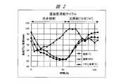
- FIG. 2 is a diagram showing a temperature and humidity freezing cycle test pattern.
- the temperature / humidity freezing cycle starts at a module temperature of -10 ° C. Under simulated sunlight, the module temperature is increased to 85 ° C in 45 minutes, then the light is turned off and the module temperature is increased to -10 ° C over 60 minutes. To lower. This is repeated as 40 cycles.
- the PV module is tested with these two types of cycles as a set.
- the feature of this test is that it simulates the actual usage environment, such that the temperature / humidity cycle is equivalent to one year in spring / summer fall and the temperature / humidity freezing cycle is equivalent to winter.
- the temperature cycle test in the IEC61215 standard is a test in which the temperature in the bath is set to one cycle for a maximum of 6 hours from ⁇ 40 ° C. to + 85 ° C., and this is repeated 200 cycles. During this cycle, a constant current is passed through the PV module in the temperature range of + 25 ° C. or higher, but no light irradiation is performed.
- the temperature cycle test disclosed in Patent Document 1 is also energized for the purpose of impedance measurement only while the temperature in the tank is changed although energization is performed.
- the temperature / humidity cycle test and temperature / humidity freezing cycle test are highly reproducible in actual use environment, but are not energized. Further, the upper limit of the temperature in the tank of the temperature cycle is 65 ° C., which is due to the operating limit of the lamp used for the pseudo solar light source at a high temperature.
- a typical object of the present invention is to accelerate the PV module over the limit of the operating temperature range of the pseudo solar light source used in the accelerated test while maintaining the correlation with the actual usage environment of the PV module. And providing a test method and a test apparatus for efficiently detecting deterioration of the PV module.
- a typical solar cell module reliability test method is a reliability test method in which the reliability of a solar cell module is tested by a test apparatus.
- the reliability test method includes a temperature cycle test step in which the temperature is periodically changed between a first temperature and a second temperature that is higher than the first temperature.
- the solar cell module is irradiated with pseudo-sunlight in a range where the temperature is higher than a third temperature within the range of the first temperature and the second temperature; and A step of energizing the solar cell module in a range where the temperature is higher than a third temperature; a step of controlling the humidity around the solar cell module in a range where the temperature is higher than the third temperature; Detecting deterioration of the solar cell module by measuring electrical characteristics of the solar cell module in a temperature range within a temperature cycle determined by the first temperature and the second temperature.
- a typical solar cell module reliability test apparatus is a reliability test apparatus for testing the reliability of a solar cell module.
- the reliability test apparatus includes a control unit that controls a temperature cycle test process that periodically changes the temperature between a first temperature and a second temperature that is higher than the first temperature.
- the solar cell module is irradiated with pseudo-sunlight in a range where the temperature is higher than a third temperature within the range of the first temperature and the second temperature; and A step of energizing the solar cell module in a range where the temperature is higher than a third temperature; a step of controlling the humidity around the solar cell module in a range where the temperature is higher than the third temperature; Detecting deterioration of the solar cell module by measuring electrical characteristics of the solar cell module in a temperature range within a temperature cycle determined by the first temperature and the second temperature.
- the typical effect is that the PV module is heated beyond the limit of the operating temperature range of the pseudo solar light source used in the acceleration test while maintaining the correlation with the actual usage environment of the PV module, and It is possible to provide a test method and a test apparatus for efficiently detecting deterioration of a PV module.
- the constituent elements are not necessarily indispensable unless otherwise specified and apparently essential in principle. Needless to say.
- the shapes, positional relationships, etc. of the components, etc. when referring to the shapes, positional relationships, etc. of the components, etc., the shapes are substantially the same unless otherwise specified, or otherwise apparent in principle. And the like are included. The same applies to the above numerical values and ranges.
- a typical solar cell module reliability test method of the present embodiment is a reliability test method for testing the reliability of a solar cell module (PV module 2) using a test apparatus (reliability test apparatus 1). is there.
- the reliability test method includes a temperature cycle test step (FIGS. 4, 10, and 10) in which the temperature is periodically changed between a first temperature and a second temperature that is higher than the first temperature. 11).
- the solar cell module is irradiated with pseudo-sunlight in a range where the temperature is higher than a third temperature within the range of the first temperature and the second temperature; and A step of energizing the solar cell module in a range where the temperature is higher than a third temperature; a step of controlling the humidity around the solar cell module in a range where the temperature is higher than the third temperature; Detecting deterioration of the solar cell module by measuring electrical characteristics of the solar cell module in a temperature range within a temperature cycle determined by the first temperature and the second temperature.
- a typical solar cell module reliability test apparatus of the present embodiment is a reliability test apparatus (reliability test apparatus 1) for testing the reliability of the solar cell module (PV module 2).
- the reliability test apparatus includes a control unit (control PC11) that controls a temperature cycle test process that periodically changes a temperature between a first temperature and a second temperature that is higher than the first temperature. ).
- the solar cell module is irradiated with pseudo-sunlight in a range where the temperature is higher than a third temperature within the range of the first temperature and the second temperature; and A step of energizing the solar cell module in a range where the temperature is higher than a third temperature; a step of controlling the humidity around the solar cell module in a range where the temperature is higher than the third temperature; Detecting deterioration of the solar cell module by measuring electrical characteristics of the solar cell module in a temperature range within a temperature cycle determined by the first temperature and the second temperature.
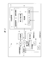
- FIG. 3 is a diagram illustrating an example of the configuration of the reliability test apparatus for the solar cell module according to the present embodiment.
- the solar cell module reliability test apparatus 1 is an acceleration test apparatus for performing an acceleration test of the PV module 2, and includes an acceleration test machine 3, a light source power source 9, an electronic load 10, a control PC 11, Interfaces (I / F) 12, 13, 14, 15 and the like are configured.
- the acceleration test machine 3 includes a thermostatic chamber 4, a temperature control unit 5, a humidity control unit 6, and the like.
- the thermostatic chamber 4 includes a pseudo solar light source 7 and a solar radiation meter 8.
- the acceleration test machine 3 is provided with a thermostatic chamber 4 for testing the PV module 2 and a temperature control unit 5 and a humidity control unit 6 for changing the atmospheric conditions of the internal space of the thermostatic chamber 4.
- the temperature control unit 5 is a control unit that controls the temperature of the internal space of the thermostatic chamber 4.
- the humidity control unit 6 is a control unit that controls the humidity of the internal space of the thermostatic chamber 4.
- the thermostat 4 of the acceleration test machine 3 can control each of temperature and humidity.
- a pseudo solar light source 7 that irradiates pseudo sunlight is installed, and the pseudo solar light 7 can be irradiated to the PV module 2 from the pseudo solar light source 7. It has become.
- a light source 9 that supplies power to the simulated solar light source 7 is installed outside the acceleration tester 3, and the light source 9 and the simulated solar light source 7 are connected by a power cable.
- a solar radiation meter 8 for measuring the amount of solar radiation from the simulated solar light source 7 is installed in the internal space of the thermostatic chamber 4 of the acceleration test machine 3. The optical output can be monitored.
- the PV module 2 to be subjected to the acceleration test is appropriately placed on a jig and installed in the internal space of the thermostatic chamber 4 of the acceleration test machine 3.
- the position of the PV module 2 and the position of the pseudo solar light source 7 can be adjusted so that the pseudo solar light from the pseudo solar light source 7 is uniformly irradiated to the PV module 2.
- the output of the PV module 2 is led out of the thermostatic chamber 4 of the acceleration test machine 3 and connected to the electronic load 10.
- the electronic load 10 has a configuration capable of controlling the output of the PV module 2 used for the test.
- the control PC 11 is electrically connected to the acceleration tester 3, the pyranometer 8, the light source 9, the electronic load 10, the PV module 2, and the like, and exchanges necessary signals and information with these elements. And each control based on it is possible.
- the control PC 11 also functions as a control unit that controls a temperature cycle test process described later.
- Control PC11 takes in the time signal emitted from the acceleration tester 3, and controls the ON / OFF of the artificial solar light source 7 and the electronic load 10 at an appropriate timing during the test using the signal as a trigger. Further, in addition to the output of the pyranometer 8, the temperature of the PV module 2 is monitored with a thermocouple, and the output of this thermocouple is also taken into the control PC 11. In addition, measured values of I (current) and V (voltage) of the PV module 2 can be taken into the control PC 11 via the electronic load 10. Each piece of information taken into the control PC 11 is taken into the control PC 11 via the I / Fs 12, 13, 14, and 15 as necessary (shown in FIG. 3).
- the reliability test apparatus 1 for the PV module 2 configured as described above, as a feature, all of the stresses that are received in the actual usage environment of the PV module 2 are temperature cycle, temperature difference, humidity, light irradiation, and energization. Take advantage of the test. Further, in order to set the current to be supplied to the PV module 2 in the vicinity of the maximum power point, the PV module 2 is energized so as to maintain the current value corresponding to the maximum power point, and only the voltage is monitored at that time. 2 is detected. This will be described in detail below.
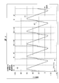
- FIG. 4 is a diagram showing an example of a temperature cycle test pattern in the reliability test method by the PV module reliability test apparatus of FIG.
- time is plotted on the horizontal axis and temperature is plotted on the vertical axis as the temperature cycle test pattern of the temperature cycle test process.
- 41 is a temperature cycle pattern and shows the temperature setting value of the thermostat 4.
- the example of FIG. 4 shows a cycle pattern in which the temperature is periodically changed between a first temperature of ⁇ 10 ° C. and a second temperature of 60 ° C., which is higher than the first temperature.
- Reference numeral 42 denotes a region that is constant at a temperature of 25 ° C., which is a third temperature within a range of ⁇ 10 ° C. and 60 ° C., in the temperature cycle pattern. Thus, the characteristics of the PV module 2 are acquired.
- 43 is an area where light irradiation ON, energization ON, and humidity control are performed. That is, in the region where the temperature indicated by 43 is 25 ° C. or higher, the pseudo solar light source 7 is turned on and the PV module 2 is irradiated with light. At the same time, the electronic load 10 is appropriately set, and the PV module 2 generates power and energization is performed by supplying power to the electronic load 10.
- This temperature cycle test pattern applies a temperature difference, temperature cycle, humidity, light irradiation, and energization stress to the PV module 2.
- Each cycle of the temperature cycle test process according to this temperature cycle test pattern includes a first time range (region 43), a second time range (region 42), and a third time range (first time range and Time range excluding the second time range).
- This temperature cycle test process is controlled by a control mechanism built in the acceleration tester 3 or the control PC 11 constituting the reliability test apparatus 1 described above.
- a step of irradiating the PV module 2 (light irradiation ON), a step of energizing the PV module 2 (energization ON), and a step of controlling the humidity around the PV module 2 ( Humidity control).
- the pseudo-sunlight is irradiated to the PV module 2 in a range where the temperature is higher than 25 ° C.
- the PV module 2 is energized in a range where the temperature is higher than 25 ° C.
- the humidity control the humidity around the PV module 2 is controlled in a range where the temperature is higher than 25 ° C.
- the second time range (area 42) is a time range before the first time range, and in this second time range, the process of measuring the electrical characteristics of the PV module 2 is performed.
- the degradation of the PV module 2 is measured by measuring the electrical characteristics of the PV module 2 in a constant region of 25 ° C., which is a temperature range within a temperature cycle determined by ⁇ 10 ° C. and 60 ° C. To detect.
- the third time range is a time range after the first time range, and light irradiation ON and energization ON are not performed in this third time range.
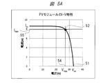
- FIG. 5A is a diagram illustrating an example of a current-voltage characteristic curve of a PV module.
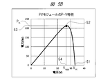
- FIG. 5B is a diagram illustrating an example of a power-voltage characteristic curve of the PV module.
- the PV module 2 has, for example, a plurality of cells arranged in a grid and wiring portions that connect the cells, and includes a positive terminal and a negative terminal that are connected to the outside. Current-voltage characteristics and power-voltage characteristics can be obtained through the positive terminal and the negative terminal connected to the outside.
- the horizontal axis represents voltage and the vertical axis represents current.
- the horizontal axis represents voltage and the vertical axis represents power.
- the current (I) -voltage (V) characteristics of the PV module generally have characteristics as shown in FIG. 5A, and the corresponding power (P) -voltage (V) characteristics generally have characteristics as shown in FIG. 5B. Have.
- 51 is an open circuit voltage V OC of the PV module 2.
- An IV characteristic curve of the PV module 2 can be obtained by operating the electronic load 10 in the constant voltage mode, operating at an appropriately set voltage interval from 0 V to V OC and reading the load current value at that time.
- . 52 is the maximum power point of the PV module 2.
- 53 is the maximum power value of the PV module 2.
- the maximum power P m that is the maximum power value 53 is output.
- Reference numerals 54 and 55 denote a voltage value and a current value at the maximum power point 52 of the PV module 2.
- the voltage value 54 corresponding to the maximum power value 53 of the maximum power point 52 becomes the operating voltage V mpp and the current value 55 becomes the operating current I mpp .
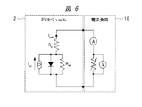
- FIG. 6 is a diagram illustrating an example of an equivalent circuit when an electronic load is connected to the PV module.
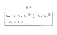
- FIG. 7 is a diagram illustrating an example of an expression representing the voltage and current of the PV module.
- the PV module 2 can be represented as an equivalent circuit by a current source, a diode, and a shunt resistor R sh connected in parallel, and a series resistor R s connected in series to this parallel connected circuit.
- the electronic load 10 can be represented by a variable resistor, a voltmeter connected in parallel to the variable resistor, and an ammeter connected in series to the variable resistor.
- FIG. 7 is an equation representing the current I module and the voltage V of the PV module 2 in the equivalent circuit of FIG.
- the current I module is measured by an ammeter of the electronic load 10 and the voltage V is measured by a voltmeter.
- I cell is the cell current of the PV modules 2
- I sc is the short circuit current
- p is the solar radiation (kW / m 2)
- I s is the reverse saturation current of the diode
- e is elementary charge
- V j is the junction voltage of the PN junction
- n f is a diode constant
- k is a Boltzmann constant
- T is an absolute temperature
- N is the number of cells constituting the PV module 2.
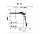
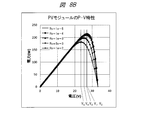
- FIG. 8A is a diagram illustrating an example of changes in current-voltage characteristics of a PV module when the PV module deteriorates.
- FIG. 8B is a diagram illustrating an example of a change in power-voltage characteristics of the PV module when the PV module deteriorates.
- FIG. 8A shows voltage and the vertical axis represents current.
- FIG. 8B similarly to FIG. 5A described above, the horizontal axis represents voltage and the vertical axis represents power.
- FIG. 8B shows power (P) -voltage (V) characteristics corresponding to the current (I) -voltage (V) characteristics shown in FIG. 8A.
- 8A and 8B show an example in which, among the shunt resistance R sh and the series resistance R s of the PV module 2, the series resistance R s is deteriorated due to stress.
- the operating voltage at the maximum power point with respect to the change in R s changes from V 1 to V 2 , V 3 , V 4 , V 5 . Is very small as indicated by ⁇ I. In particular, there is almost no change at the initial stage of deterioration.
- the operation setting at the time of energization is performed by operating the electronic load 10 in the constant current mode. Is set so as to be positioned at the maximum power point, even if the PV module 2 is deteriorated, the maximum power point can be held substantially without changing the setting of the electronic load 10. At this time, the deterioration of the PV module 2 can be detected by monitoring only the voltage change.
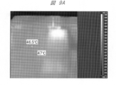
- FIG. 9A is a diagram illustrating an example of a temperature distribution on the surface of the PV module when the PV module is irradiated with a pseudo solar light source at a set temperature in the acceleration test machine.
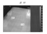
- 9B is a diagram illustrating an example of the temperature distribution on the surface of the PV module when the PV module is irradiated with a pseudo solar light source at a set temperature in the acceleration test machine and the PV module is operated with an energization current.
- 9A and 9B show how the temperature of the PV module 2 is when the temperature cycle test is performed as described above.
- the gradation is such that from black to white in order from the lower temperature to the higher temperature.
- the temperature level corresponding to this shading is displayed as a bar (absolute temperature) on the right side.
- FIG. 9A when the PV module 2 is irradiated with pseudo-sunlight from the pseudo-solar light source 7 with a light output of 1 (kW / m 2 ) in a state where the temperature chamber 4 of the acceleration tester 3 is set to 25 ° C.
- the surface temperature of the PV module 2 was observed with an infrared camera. This observation shows that the surface temperature of the PV module 2 is about 47 ° C. (46.5 ° C., points of 47 ° C. are displayed), and the temperature is about 22 ° C. higher than the set temperature in the thermostat 4.
- FIG. 9B shows the PV module in the state shown in FIG. 9A (with the thermostat 4 of the acceleration tester 3 set to 25 ° C., with the artificial sunlight from the pseudo solar light source 7 having a light output of 1 (kW / m 2 )).
- 2 is a surface temperature distribution of the PV module 2 when the electronic load 10 is set so that a load current (about 8 A in the present embodiment) corresponding to the maximum power point flows by energization.
- the wiring portion of the PV module 2 is heated to about 70 ° C. (indicating points of 68 ° C. and 71 ° C.), and is heated by about 45 ° C. from the set temperature in the thermostat 4 by energization. .
- the PV module 2 in addition to the light irradiation, by energizing so as to pass a current corresponding to the maximum power point, only the PV module 2 can be heated to about 45 ° C. from the temperature setting in the thermostat 4. Since such a temperature rise is also seen when the set temperature in the thermostat 4 is 50 ° C., the same temperature rise is usually obtained up to about 85 ° C., which is a temperature range in which the PV module 2 is accelerated. It can be expected to occur. Next, the temperature rise pattern of the PV module when energized in addition to this light irradiation will be described.
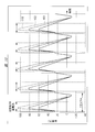
- FIG. 10 is a diagram showing an example of a temperature rise pattern of the PV module in the temperature cycle test pattern when only light irradiation is performed and when energization is performed in addition to light irradiation.
- FIG. 10 shows the temperature rise pattern of the PV module 2 due to light irradiation and the temperature rise pattern of the PV module 2 when energized in addition to light irradiation in the temperature cycle test pattern shown in FIG.
- 101 is a set temperature pattern in the thermostat 4 corresponding to the temperature cycle test pattern of FIG.
- Reference numeral 102 denotes a temperature cycle pattern of the PV module 2 when irradiated with light.
- Reference numeral 103 denotes a temperature cycle pattern of the PV module 2 when energization is performed in addition to light irradiation.
- the set temperature pattern 101 in the thermostat 4 periodically changes the temperature between ⁇ 10 ° C. and 60 ° C.
- the characteristics of the PV module 2 are acquired in a region which is constant at 25 ° C. between ⁇ 10 ° C. and 60 ° C. In the region of 25 ° C. or higher, the pseudo solar light source 7 is turned on and the PV module 2 is irradiated with light.
- the electronic load 10 is appropriately set, and the PV module 2 generates power and energization is performed by supplying power to the electronic load 10.
- the PV module 2 is heated beyond the limit of the operating temperature range of the pseudo solar light source 7 used in the acceleration test while maintaining the correlation with the actual use environment of the PV module 2, and the efficiency is increased.
- the reliability test method and the reliability test apparatus 1 for detecting the deterioration of the PV module 2 can be provided. That is, when performing an accelerated test of the PV module 2, it is possible to heat the PV module 2 exceeding the operating temperature range of the simulated solar light source 7 even under irradiation of simulated sunlight while maintaining correspondence with the actual use environment. And degradation of the PV module 2 can be efficiently detected.
- the number of cycles within a predetermined time in the temperature cycle test step is at least one of the first temperature and the second temperature (in this embodiment, an example of the second temperature is described,
- the temperature can be changed based on the temperature of the PV module corresponding to the temperature of the PV module.
- the temperature setting in the thermostatic chamber is determined in consideration of the temperature rise due to light irradiation and energization.
- FIG. 11 is a diagram illustrating an example of a temperature cycle test pattern in a case where the temperature setting in the thermostatic chamber is determined in consideration of the temperature increase due to light irradiation and energization.
- FIG. 11 shows a temperature cycle pattern in which the temperature setting in the thermostatic chamber is determined so that the maximum temperature becomes 85 ° C. in consideration of the temperature rise of the PV module due to light irradiation and energization.
- the temperature cycle pattern of the PV module 2 can be expected to increase by about 45 ° C. with respect to the set temperature pattern in the thermostat 4 by light irradiation and energization. I understood. Therefore, FIG. 11 shows the temperature setting pattern in the thermostat 4 determined so that the maximum temperature is 85 ° C. in accordance with the temperature cycle test of IEC61215.
- reference numeral 121 denotes a set temperature pattern in the thermostatic chamber 4.
- Reference numeral 122 denotes a temperature cycle pattern of the PV module 2 when irradiated with light.
- 123 is a temperature cycle pattern of the PV module 2 when energization is performed in addition to light irradiation.
- the set temperature pattern 121 in the thermostatic chamber 4 periodically changes in temperature between ⁇ 10 ° C. and 40 ° C.
- the temperature in the thermostat 4 may be about 40 ° C. at the maximum, and the temperature cycle width in the thermostat 4 becomes small, so the time required for one cycle is shortened. For this reason, the number of temperature cycles within a certain time can be increased more than the pattern shown in FIG. 4 or FIG. 10 of the first embodiment described above.
- the present invention made by the present inventor has been specifically described based on the embodiment.
- the present invention is not limited to the embodiment, and various modifications can be made without departing from the spirit of the invention. Needless to say.
- the above-described embodiment has been described in detail for easy understanding of the present invention, and is not necessarily limited to one having all the configurations described.
- a part of the configuration of one embodiment can be replaced with the configuration of another embodiment, and the configuration of another embodiment can be added to the configuration of one embodiment. .
- SYMBOLS 1 Reliability test apparatus, 2 ... PV module (solar cell module), 3 ... Acceleration test machine, 4 ... Constant temperature bath, 5 ... Temperature control part, 6 ... Humidity control part, 7 ... Pseudo solar light source, 8 ... Solar radiation meter , 9 ... Light source power supply, 10 ... Electronic load, 11 ... Control PC, 12, 13, 14, 15 ... I / F, 41 ... temperature cycle pattern, 42 ... region where temperature is constant at 25 ° C, 43 ... region where light irradiation is ON, energization is ON, humidity control is performed, 51 ... Open voltage of PV module, 52 ... Maximum power point of PV module, 53 ...
- Maximum power value of PV module 54 ... Voltage value at maximum power point of PV module, 55 ... Current at maximum power point of PV module value, 101 ... Set temperature pattern in the thermostat, 102 ... PV module temperature cycle pattern when irradiated with light, 103 ... PV module temperature cycle pattern when energized in addition to light irradiation, 121 ... Set temperature pattern in the thermostat, 122 ... PV module temperature cycle pattern when irradiated with light, 123 ... PV module temperature cycle pattern when energized in addition to light irradiation.
Landscapes
- Testing Of Individual Semiconductor Devices (AREA)
- Photovoltaic Devices (AREA)
- Testing Resistance To Weather, Investigating Materials By Mechanical Methods (AREA)
Abstract
L'invention concerne un procédé de test et un dispositif de test qui permettent de chauffer un module photovoltaïque (PV) au-delà de la limite d'une plage d'utilisation de température d'une source de lumière solaire simulée utilisée dans un test accéléré qui maintient la corrélation avec un environnement d'utilisation réelle du module PV et détecte efficacement sa dégradation. Le test est effectué en tenant compte de tous les éléments suivants : cycle de température, différence de température, humidité, éclairage de lumière et électrification, qui sont des contraintes auxquelles le module PV est soumis dans l'environnement d'utilisation réelle. Du fait que le courant qui traverse le module PV est réglé à un point de puissance maximum, l'électrification est effectuée de telle sorte que la valeur de courant correspondant au point de puissance maximum est maintenue. La dégradation du module PV est ensuite détectée par surveillance unique de la tension.
Priority Applications (1)
| Application Number | Priority Date | Filing Date | Title |
|---|---|---|---|
| PCT/JP2013/066379 WO2014199495A1 (fr) | 2013-06-13 | 2013-06-13 | Procédé de test de fiabilité de module de cellule photovoltaïque et dispositif de test de fiabilité |
Applications Claiming Priority (1)
| Application Number | Priority Date | Filing Date | Title |
|---|---|---|---|
| PCT/JP2013/066379 WO2014199495A1 (fr) | 2013-06-13 | 2013-06-13 | Procédé de test de fiabilité de module de cellule photovoltaïque et dispositif de test de fiabilité |
Publications (1)
| Publication Number | Publication Date |
|---|---|
| WO2014199495A1 true WO2014199495A1 (fr) | 2014-12-18 |
Family
ID=52021825
Family Applications (1)
| Application Number | Title | Priority Date | Filing Date |
|---|---|---|---|
| PCT/JP2013/066379 Ceased WO2014199495A1 (fr) | 2013-06-13 | 2013-06-13 | Procédé de test de fiabilité de module de cellule photovoltaïque et dispositif de test de fiabilité |
Country Status (1)
| Country | Link |
|---|---|
| WO (1) | WO2014199495A1 (fr) |
Cited By (4)
| Publication number | Priority date | Publication date | Assignee | Title |
|---|---|---|---|---|
| CN104821789A (zh) * | 2015-05-06 | 2015-08-05 | 国家电网公司 | 一种光伏发电系统可靠性的检测方法 |
| CN104868844A (zh) * | 2015-05-22 | 2015-08-26 | 徐州工程学院 | 太阳能电池高低温光伏特性测试实验台 |
| CN108092621A (zh) * | 2017-11-14 | 2018-05-29 | 中国电器科学研究院有限公司 | 一种利用光伏背板的温湿度老化试验加速比计算模型来预测光伏背板加速老化的方法 |
| CN111007102A (zh) * | 2019-12-17 | 2020-04-14 | 河海大学常州校区 | 一种光伏组件温湿度加速老化因子的计算方法 |
Citations (1)
| Publication number | Priority date | Publication date | Assignee | Title |
|---|---|---|---|---|
| JP2005228951A (ja) * | 2004-02-13 | 2005-08-25 | Canon Inc | 光起電力素子とその製造方法 |
-
2013
- 2013-06-13 WO PCT/JP2013/066379 patent/WO2014199495A1/fr not_active Ceased
Patent Citations (1)
| Publication number | Priority date | Publication date | Assignee | Title |
|---|---|---|---|---|
| JP2005228951A (ja) * | 2004-02-13 | 2005-08-25 | Canon Inc | 光起電力素子とその製造方法 |
Non-Patent Citations (1)
| Title |
|---|
| MAKOTO KONAGAI ET AL., TAIYO DENCHI NO KISO TO OYO, 20 July 2010 (2010-07-20), pages 396 - 398 * |
Cited By (5)
| Publication number | Priority date | Publication date | Assignee | Title |
|---|---|---|---|---|
| CN104821789A (zh) * | 2015-05-06 | 2015-08-05 | 国家电网公司 | 一种光伏发电系统可靠性的检测方法 |
| CN104821789B (zh) * | 2015-05-06 | 2017-08-11 | 国家电网公司 | 一种光伏发电系统可靠性的检测方法 |
| CN104868844A (zh) * | 2015-05-22 | 2015-08-26 | 徐州工程学院 | 太阳能电池高低温光伏特性测试实验台 |
| CN108092621A (zh) * | 2017-11-14 | 2018-05-29 | 中国电器科学研究院有限公司 | 一种利用光伏背板的温湿度老化试验加速比计算模型来预测光伏背板加速老化的方法 |
| CN111007102A (zh) * | 2019-12-17 | 2020-04-14 | 河海大学常州校区 | 一种光伏组件温湿度加速老化因子的计算方法 |
Similar Documents
| Publication | Publication Date | Title |
|---|---|---|
| Gallardo-Saavedra et al. | Nondestructive characterization of solar PV cells defects by means of electroluminescence, infrared thermography, I–V curves and visual tests: Experimental study and comparison | |
| Ding et al. | A MATLAB-simulink-based PV module model and its application under conditions of nonuniform irradiance | |
| Niyaz et al. | Impact of cracks on crystalline silicon photovoltaic modules temperature distribution | |
| Bellini et al. | Simplified model of a photovoltaic module | |
| Huang et al. | Solar cell junction temperature measurement of PV module | |
| Dirnberger et al. | Uncertainty in PV module measurement—Part I: Calibration of crystalline and thin-film modules | |
| Spataru et al. | Combined-accelerated stress testing system for photovoltaic modules | |
| Schuss et al. | Detecting defects in photovoltaic panels with the help of synchronized thermography | |
| Hocine et al. | Automatic detection of faults in a photovoltaic power plant based on the observation of degradation indicators | |
| Andrejasic et al. | Comparison of direct maximum power point tracking algorithms using EN 50530 dynamic test procedure | |
| Wang et al. | A novel method for the determination of dynamic resistance for photovoltaic modules | |
| Erkaya et al. | On-site characterization of PV modules using a portable, MOSFET-based capacitive load | |
| Rachid | Tracing current-voltage curve of solar panel Based on LabVIEW Arduino Interfacing | |
| WO2014199495A1 (fr) | Procédé de test de fiabilité de module de cellule photovoltaïque et dispositif de test de fiabilité | |
| CN102928762B (zh) | 光伏组件热斑试验电池挑选设备 | |
| Kessaissia et al. | Comparison of two PV modules technologies using analytical and experimental methods | |
| Liu et al. | Characterizing photovoltaic module power degradation through impedance spectroscopy: Transitioning to outdoor applications | |
| CN109756188B (zh) | 一种双面太阳电池组件电性能测试方法及装置 | |
| Leite et al. | Low-cost instrument for tracing current-voltage characteristics of photovoltaic modules | |
| Guerriero et al. | A simple test-bench to evaluate partial shading effects on the MPPT efficiency of a PV inverter | |
| El-Saadawi et al. | A proposed dynamic model of Photovoltaic-DG system | |
| Adamo et al. | A tool for photovoltaic panels modeling and testing | |
| CN117639663A (zh) | 光伏组件的测试系统、方法和存储介质 | |
| Vemula et al. | Power rating of photovoltaic modules per IEC 61853-1 standard using a new outdoor test method | |
| Velkovski et al. | Application of Incremental Conductance MPPT method for a photovoltaic generator in LabView |
Legal Events
| Date | Code | Title | Description |
|---|---|---|---|
| 121 | Ep: the epo has been informed by wipo that ep was designated in this application |
Ref document number: 13886956 Country of ref document: EP Kind code of ref document: A1 |
|
| NENP | Non-entry into the national phase |
Ref country code: DE |
|
| 122 | Ep: pct application non-entry in european phase |
Ref document number: 13886956 Country of ref document: EP Kind code of ref document: A1 |
|
| NENP | Non-entry into the national phase |
Ref country code: JP |