WO2014199603A1 - 情報提示装置 - Google Patents
情報提示装置 Download PDFInfo
- Publication number
- WO2014199603A1 WO2014199603A1 PCT/JP2014/003000 JP2014003000W WO2014199603A1 WO 2014199603 A1 WO2014199603 A1 WO 2014199603A1 JP 2014003000 W JP2014003000 W JP 2014003000W WO 2014199603 A1 WO2014199603 A1 WO 2014199603A1
- Authority
- WO
- WIPO (PCT)
- Prior art keywords
- light
- light emitting
- information
- information presentation
- presentation device
- Prior art date
- Legal status (The legal status is an assumption and is not a legal conclusion. Google has not performed a legal analysis and makes no representation as to the accuracy of the status listed.)
- Ceased
Links
Images







Classifications
-
- B—PERFORMING OPERATIONS; TRANSPORTING
- B60—VEHICLES IN GENERAL
- B60K—ARRANGEMENT OR MOUNTING OF PROPULSION UNITS OR OF TRANSMISSIONS IN VEHICLES; ARRANGEMENT OR MOUNTING OF PLURAL DIVERSE PRIME-MOVERS IN VEHICLES; AUXILIARY DRIVES FOR VEHICLES; INSTRUMENTATION OR DASHBOARDS FOR VEHICLES; ARRANGEMENTS IN CONNECTION WITH COOLING, AIR INTAKE, GAS EXHAUST OR FUEL SUPPLY OF PROPULSION UNITS IN VEHICLES
- B60K35/00—Instruments specially adapted for vehicles; Arrangement of instruments in or on vehicles
- B60K35/10—Input arrangements, i.e. from user to vehicle, associated with vehicle functions or specially adapted therefor
-
- B—PERFORMING OPERATIONS; TRANSPORTING
- B60—VEHICLES IN GENERAL
- B60K—ARRANGEMENT OR MOUNTING OF PROPULSION UNITS OR OF TRANSMISSIONS IN VEHICLES; ARRANGEMENT OR MOUNTING OF PLURAL DIVERSE PRIME-MOVERS IN VEHICLES; AUXILIARY DRIVES FOR VEHICLES; INSTRUMENTATION OR DASHBOARDS FOR VEHICLES; ARRANGEMENTS IN CONNECTION WITH COOLING, AIR INTAKE, GAS EXHAUST OR FUEL SUPPLY OF PROPULSION UNITS IN VEHICLES
- B60K35/00—Instruments specially adapted for vehicles; Arrangement of instruments in or on vehicles
- B60K35/20—Output arrangements, i.e. from vehicle to user, associated with vehicle functions or specially adapted therefor
- B60K35/21—Output arrangements, i.e. from vehicle to user, associated with vehicle functions or specially adapted therefor using visual output, e.g. blinking lights or matrix displays
- B60K35/23—Head-up displays [HUD]
-
- B—PERFORMING OPERATIONS; TRANSPORTING
- B60—VEHICLES IN GENERAL
- B60K—ARRANGEMENT OR MOUNTING OF PROPULSION UNITS OR OF TRANSMISSIONS IN VEHICLES; ARRANGEMENT OR MOUNTING OF PLURAL DIVERSE PRIME-MOVERS IN VEHICLES; AUXILIARY DRIVES FOR VEHICLES; INSTRUMENTATION OR DASHBOARDS FOR VEHICLES; ARRANGEMENTS IN CONNECTION WITH COOLING, AIR INTAKE, GAS EXHAUST OR FUEL SUPPLY OF PROPULSION UNITS IN VEHICLES
- B60K35/00—Instruments specially adapted for vehicles; Arrangement of instruments in or on vehicles
- B60K35/20—Output arrangements, i.e. from vehicle to user, associated with vehicle functions or specially adapted therefor
- B60K35/28—Output arrangements, i.e. from vehicle to user, associated with vehicle functions or specially adapted therefor characterised by the type of the output information, e.g. video entertainment or vehicle dynamics information; characterised by the purpose of the output information, e.g. for attracting the attention of the driver
-
- B—PERFORMING OPERATIONS; TRANSPORTING
- B60—VEHICLES IN GENERAL
- B60K—ARRANGEMENT OR MOUNTING OF PROPULSION UNITS OR OF TRANSMISSIONS IN VEHICLES; ARRANGEMENT OR MOUNTING OF PLURAL DIVERSE PRIME-MOVERS IN VEHICLES; AUXILIARY DRIVES FOR VEHICLES; INSTRUMENTATION OR DASHBOARDS FOR VEHICLES; ARRANGEMENTS IN CONNECTION WITH COOLING, AIR INTAKE, GAS EXHAUST OR FUEL SUPPLY OF PROPULSION UNITS IN VEHICLES
- B60K35/00—Instruments specially adapted for vehicles; Arrangement of instruments in or on vehicles
- B60K35/20—Output arrangements, i.e. from vehicle to user, associated with vehicle functions or specially adapted therefor
- B60K35/28—Output arrangements, i.e. from vehicle to user, associated with vehicle functions or specially adapted therefor characterised by the type of the output information, e.g. video entertainment or vehicle dynamics information; characterised by the purpose of the output information, e.g. for attracting the attention of the driver
- B60K35/285—Output arrangements, i.e. from vehicle to user, associated with vehicle functions or specially adapted therefor characterised by the type of the output information, e.g. video entertainment or vehicle dynamics information; characterised by the purpose of the output information, e.g. for attracting the attention of the driver for improving awareness by directing driver's gaze direction or eye points
-
- B—PERFORMING OPERATIONS; TRANSPORTING
- B60—VEHICLES IN GENERAL
- B60K—ARRANGEMENT OR MOUNTING OF PROPULSION UNITS OR OF TRANSMISSIONS IN VEHICLES; ARRANGEMENT OR MOUNTING OF PLURAL DIVERSE PRIME-MOVERS IN VEHICLES; AUXILIARY DRIVES FOR VEHICLES; INSTRUMENTATION OR DASHBOARDS FOR VEHICLES; ARRANGEMENTS IN CONNECTION WITH COOLING, AIR INTAKE, GAS EXHAUST OR FUEL SUPPLY OF PROPULSION UNITS IN VEHICLES
- B60K35/00—Instruments specially adapted for vehicles; Arrangement of instruments in or on vehicles
- B60K35/20—Output arrangements, i.e. from vehicle to user, associated with vehicle functions or specially adapted therefor
- B60K35/29—Instruments characterised by the way in which information is handled, e.g. showing information on plural displays or prioritising information according to driving conditions
-
- B—PERFORMING OPERATIONS; TRANSPORTING
- B60—VEHICLES IN GENERAL
- B60K—ARRANGEMENT OR MOUNTING OF PROPULSION UNITS OR OF TRANSMISSIONS IN VEHICLES; ARRANGEMENT OR MOUNTING OF PLURAL DIVERSE PRIME-MOVERS IN VEHICLES; AUXILIARY DRIVES FOR VEHICLES; INSTRUMENTATION OR DASHBOARDS FOR VEHICLES; ARRANGEMENTS IN CONNECTION WITH COOLING, AIR INTAKE, GAS EXHAUST OR FUEL SUPPLY OF PROPULSION UNITS IN VEHICLES
- B60K35/00—Instruments specially adapted for vehicles; Arrangement of instruments in or on vehicles
- B60K35/60—Instruments characterised by their location or relative disposition in or on vehicles
-
- B—PERFORMING OPERATIONS; TRANSPORTING
- B60—VEHICLES IN GENERAL
- B60K—ARRANGEMENT OR MOUNTING OF PROPULSION UNITS OR OF TRANSMISSIONS IN VEHICLES; ARRANGEMENT OR MOUNTING OF PLURAL DIVERSE PRIME-MOVERS IN VEHICLES; AUXILIARY DRIVES FOR VEHICLES; INSTRUMENTATION OR DASHBOARDS FOR VEHICLES; ARRANGEMENTS IN CONNECTION WITH COOLING, AIR INTAKE, GAS EXHAUST OR FUEL SUPPLY OF PROPULSION UNITS IN VEHICLES
- B60K35/00—Instruments specially adapted for vehicles; Arrangement of instruments in or on vehicles
- B60K35/80—Arrangements for controlling instruments
-
- B—PERFORMING OPERATIONS; TRANSPORTING
- B60—VEHICLES IN GENERAL
- B60K—ARRANGEMENT OR MOUNTING OF PROPULSION UNITS OR OF TRANSMISSIONS IN VEHICLES; ARRANGEMENT OR MOUNTING OF PLURAL DIVERSE PRIME-MOVERS IN VEHICLES; AUXILIARY DRIVES FOR VEHICLES; INSTRUMENTATION OR DASHBOARDS FOR VEHICLES; ARRANGEMENTS IN CONNECTION WITH COOLING, AIR INTAKE, GAS EXHAUST OR FUEL SUPPLY OF PROPULSION UNITS IN VEHICLES
- B60K37/00—Dashboards
- B60K37/20—Dashboard panels
-
- B—PERFORMING OPERATIONS; TRANSPORTING
- B60—VEHICLES IN GENERAL
- B60K—ARRANGEMENT OR MOUNTING OF PROPULSION UNITS OR OF TRANSMISSIONS IN VEHICLES; ARRANGEMENT OR MOUNTING OF PLURAL DIVERSE PRIME-MOVERS IN VEHICLES; AUXILIARY DRIVES FOR VEHICLES; INSTRUMENTATION OR DASHBOARDS FOR VEHICLES; ARRANGEMENTS IN CONNECTION WITH COOLING, AIR INTAKE, GAS EXHAUST OR FUEL SUPPLY OF PROPULSION UNITS IN VEHICLES
- B60K2360/00—Indexing scheme associated with groups B60K35/00 or B60K37/00 relating to details of instruments or dashboards
- B60K2360/20—Optical features of instruments
- B60K2360/33—Illumination features
- B60K2360/332—Light emitting diodes
Definitions
- This disclosure relates to an information presentation device that presents information.
- a display device mounted on an automobile comprising a light emitting unit that emits light according to a control signal and a control device that controls the light emitting unit, and a display device that notifies information representing the state of the automobile according to the light emission mode of the light emitting unit Is known (see Patent Document 1).
- the light emitting section in the display device described in Patent Document 1 has light emitting diodes arranged in a row at the upper end of a meter provided on an automobile installation panel.
- the control device changes the light emission mode of the light emitting unit according to the remaining amount of fuel, the amount of light in the passenger compartment, the amount of ultraviolet rays in the passenger compartment, and the like.
- the inventors of the present application have found the following regarding the display device.
- a display unit for a navigation device and a display unit for a head-up display are provided as a display device for displaying information around the meter in the vehicle installation panel.
- the installation positions of these display units are different from the installation positions of the meters on the installation panel.
- the display unit displaying the information is notified. May be.
- the installation area of the light emitting diode constituting the light emitting section is limited to the upper end of the meter in the installation panel. For this reason, in the display device described in Patent Document 1, it is not possible to emit light around the display unit on which information to be recognized by the occupant is displayed, and indicates a display unit on which information to be recognized by the occupant is displayed. There is a possibility that it cannot be done. That is, in the display device described in Patent Document 1, there is a possibility that the occupant cannot recognize the display unit on which information that should be recognized by the occupant is displayed.
- This disclosure is intended to enable an occupant to recognize a display unit on which information to be recognized by an occupant is displayed in an information presentation device.
- An information presentation device for presenting information according to the present disclosure is a part on which information to be recognized by a user is displayed, and at least a part thereof is arranged with a deviation along a prescribed direction defined in advance.
- a light-emitting unit having a plurality of light-emitting elements arranged in a row on the plurality of display units and extending over at least a part of the periphery of each of the plurality of display units, and a control for controlling the light emission mode of the light-emitting units A part.
- the information presentation device it is possible to emit a part of the periphery of the display unit on which information to be recognized by the user is displayed, and to indicate the display unit on which the information to be recognized by the user is displayed. it can.
- the user can recognize the display unit on which information to be recognized by the user is displayed.
- the display unit on which information that should be recognized by the user is displayed can be recognized by the user.
- the information presentation device it is possible to increase the amount of information that can be notified via the light emitting unit. That is, according to the information presentation device, information can be presented by controlling the light emission mode of the light emitting unit.
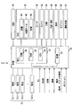
- FIG. 1 is a block diagram illustrating a schematic configuration of an information presentation device to which the present disclosure is applied and each device connected to the information presentation device.
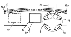
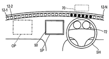
- FIG. 2 is an explanatory diagram showing an arrangement of light emitting elements constituting the information presentation device
- FIG. 3 is a diagram showing a structure of a light emitting unit constituting the information presentation device
- FIG. 4 is a flowchart showing a processing procedure of the light emission processing.
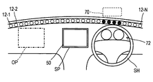
- FIG. 5A is a diagram illustrating a steady state in the embodiment
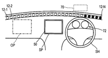
- FIG. 5B is a diagram exemplifying a first light emission mode in a case where the site requiring visual recognition is a display area in the head-up display
- FIG. 5C is a diagram illustrating a first light emission mode in a case where the site requiring visual recognition is a display area in the head-up display
- FIG. 6A is a diagram illustrating a second light emission mode in the embodiment.
- FIG. 6B is a diagram illustrating a second light emission mode in the embodiment.
- FIG. 7A is a diagram illustrating a third light emission mode in the embodiment;
- FIG. 7B is a diagram illustrating a third light emission mode in the embodiment.
- FIG. 7C is a diagram illustrating a third light emission mode in the embodiment.
- FIG. 8A is a diagram illustrating a case where warning information is displayed in the display area of the head-up display as the third light emission mode
- FIG. 8B is a diagram illustrating a third light emission mode in the embodiment
- FIG. 8C is a diagram illustrating a third light emission mode in the embodiment.
- FIG. 9A is a diagram illustrating a fourth light emission mode
- FIG. 9B is a diagram illustrating a fourth light emission mode
- FIG. 9C is a diagram illustrating a fourth light emission mode.
- An information presentation device 1 shown in FIG. 1 is mounted on an automobile and presents various information to an occupant.
- the information presentation apparatus 1 includes a light emitting unit 10 and a control unit 20.
- control unit 20 includes a storage device 22 and a microcomputer 24.
- the storage device 22 is a non-volatile storage device that can rewrite stored contents.
- the microcomputer 24 includes a ROM 26 that stores processing programs and data that need to retain stored contents even when the power is turned off, a RAM 28 that temporarily stores processing programs and data, and processes stored in the ROM 26 and RAM 28.
- a known computer having at least a CPU 30 that executes various processes according to a program is mainly configured.
- the ROM 26 stores a processing program for the microcomputer 24 to execute a light emission process for controlling the light emitting unit 10 in accordance with information from various connected devices connected to the information presentation device 1.
- the control unit 20 is connected with a head-up display 40, a navigation device 42, a monitor 50, and an in-vehicle camera 52 as connected devices.
- the head-up display 40 is a known device that displays information on a display area 70 provided on the windshield 80 (see FIG. 2).
- the navigation device 42 includes a position detector 44 that detects the current position, a map data storage unit 46 that stores map data, and a control device 48.
- This navigation device 42 is connected to the destination via the monitor 50 according to the result of the control device 48 collating the current position detected by the position detector 44 with the map data stored in the map data storage unit 46.
- This is a known device for guiding a route.
- the monitor 50 is a display device having a liquid crystal display.
- the monitor 50 may have a known touch panel function.
- the in-vehicle camera 52 is a well-known imaging device that images the situation around the host vehicle or the situation inside the host vehicle.
- a communication device 54 a peripheral monitoring device 56, a terminal connection unit 58, an air conditioner control device 60, and a driving support control device 62 are connected to the control unit 20 as connected devices.
- the communication device 54 is a known device that performs information communication.
- Information communication by the communication device 54 may be executed via a well-known wireless communication network, may be executed via well-known road-to-vehicle communication, or may be executed via well-known vehicle-to-vehicle communication. Also good.
- the periphery monitoring device 56 is a well-known device that monitors the situation around the host vehicle.
- the periphery monitoring device 56 is present in the vicinity of the own vehicle based on an exploration device that detects an object existing around the own vehicle based on the result of transmitting / receiving the exploration wave, or an image obtained by imaging the periphery of the own vehicle. Includes a camera that detects objects.
- the vicinity of the host vehicle includes a position that becomes a blind spot of the driver.
- the exploration device includes a known sonar that uses sound waves as exploration waves, a radar device that uses radio waves as exploration waves, and a lidar device (laser radar device) that uses laser light as exploration waves.
- the terminal connection unit 58 is a device to which the mobile terminal is connected, and executes information communication with the mobile terminal connected to itself. This terminal connection part 58 will output the signal showing that to the control part 20, if a portable terminal is connected.
- the portable terminal includes a known portable communication terminal, portable information device, and portable audio player.
- the air conditioner control device 60 is a well-known control device that controls an air conditioner mounted on the host vehicle.
- the air conditioner control device 60 executes temperature control for controlling the temperature in the vehicle interior by the air conditioner, air flow control for controlling the air flow into the vehicle interior, and the like. Note that the temperature control and the air volume control may be executed in accordance with information input by the user via an operation device such as a switch or a button.
- the driving support control device 62 is a well-known control device that realizes driving support control by controlling a driving system and a braking system mounted on the host vehicle.
- cruise control for maintaining the vehicle speed of the host vehicle within the allowable range from the set speed
- adaptive cruise control for maintaining the inter-vehicle distance from the preceding vehicle within the allowable range from the set distance are executed.
- an ignition signal, a door locking / unlocking signal, own vehicle state information, a speed signal, and an operation signal are input to the control unit 20.
- the ignition signal is a known signal indicating that the ignition switch is turned on.
- the door locking / unlocking signal is a signal indicating whether a door key provided in the host vehicle is locked or unlocked.
- the own vehicle state information is information representing the state of the own vehicle.
- the own vehicle state information includes various information such as the remaining amount of fuel in the internal combustion engine, the coolant temperature of the internal combustion engine, and the rotational speed (ie, the rotational speed) of the internal combustion engine per unit time.
- the speed signal is a signal that represents the vehicle speed of the host vehicle.
- the operation signal is a signal representing various operations on the own vehicle and a signal representing various operations on the in-vehicle device of the own vehicle. (Viewable site required)
- a vehicle on which the information presentation device 1 is mounted is provided with a plurality of display units (hereinafter referred to as “required visual parts”) on which information to be recognized by the user is presented. ing.
- This visually-recognized site includes, for example, the monitor 50, the display area 70 of the head-up display 40, various meters 72, and the front of the host vehicle (that is, the windshield 80).
- the monitor 50 is movable between a reference position SP defined as a center position in the vehicle width direction on the dashboard 4 and an operation position OP defined as a position in front of the passenger seat on the dashboard 4. It is. Note that a position signal indicating whether the position of the monitor 50 is the reference position SP or the operation position OP is input to the control unit 20.
- the various meters 72 display own vehicle state information such as the vehicle speed of the own vehicle, the coolant temperature, the remaining amount of fuel, and the rotational speed of the internal combustion engine.
- the various meters 72 are disposed in front of the driver's seat on the dashboard 4 and are provided so that a person seated on the driver's seat can be visually recognized from the gap of the steering wheel SH. That is, the monitor 50 and the various meters 72 are disposed so as to have a gap on one axis along the vehicle width direction.
- the display area 70 of the head-up display 40 is an area in front of the driver's seat in the windshield 80 and is provided immediately above the dashboard 4.
- the light emitting unit 10 includes a plurality of (for example, N) light emitting elements 12-1 to 12-N.
- Each light emitting element 12 includes a red light emitting diode, a green light emitting diode, and a blue light emitting diode, and can emit light in full color.
- the subscript “N” represents the number of light emitting elements 12. In the present embodiment, N is a natural number of 2 or more (for example, “100”).
- the plurality of light emitting elements 12 are arranged in a row along the vehicle width direction (corresponding to an example of the specified direction) at the upper end of the dashboard 4. Further, the plurality of light emitting elements 12 are arranged so as to be sandwiched between the monitor 50 and the windshield 80. Some of the plurality of light emitting elements 12 are arranged so as to be sandwiched between the display area 70 of the head-up display 40 and various meters 72.
- the plurality of light emitting elements 12 span at least a part of the periphery of the monitor 50 of the navigation device 42, the periphery of the display area 70 of the head-up display 40, the periphery of various meters 72, and the periphery of the windshield 80, and The monitor 50, the display area 70, various meters 72, and the windshield 80 are arranged over the periphery.
- the periphery in the monitor 50 is the upper side of the monitor 50, and the periphery in the display area 70 is the lower side of the display area 70. Further, the peripheral edge of the various meters 72 is the upper side of the various meters 72, and the peripheral edge of the windshield 80 is the lower side of the windshield 80.
- the light emitting unit 10 includes a diffusing member 14, a line control member 16, and a covering member 18.
- the diffusion member 14 is a well-known member that diffuses light.
- the diffusing member 14 is provided in the vehicle width direction so as to cover the light path from the light emitting element 12 to the vehicle interior.
- the line control member 16 is a well-known member that condenses light in one prescribed direction while suppressing light diffusion.
- the line control member 16 is provided in the vehicle width direction so as to cover the path of the light that has passed through the diffusion member 14 toward the vehicle interior.
- the covering member 18 is a thin-film member that transmits light and is formed of a colored material.
- the covering member 18 is provided in the vehicle width direction so as to cover the path of the light that has passed through the line control member 16 toward the vehicle interior. Note that the position where the covering member 18 is provided is the boundary of the dashboard 4 with the passenger compartment.
- the covering member 18 includes, for example, cloth or leather.
- the term “colored” includes a case where it is not colorless and transparent but is artificially colored or originally has a color. (Light emission treatment)
- the light emission process executed by the control unit 20 is activated when a door locking / unlocking signal indicating that the door key provided in the host vehicle is unlocked is input.
- the first illumination mode executed in S110 is, for example, that the light emitting elements 12 arranged at the periphery of the monitor 50 among all the light emitting elements 12 constituting the light emitting unit 10 have a predetermined color. It is a light emission mode that blinks at a first specified time with a specified color (for example, yellow). The first specified time is a predetermined time length.
- the steady state is a light emission mode when there is no information to be presented to the occupant, for example, a mode in which the next light emission is executed.
- the steady state in the present embodiment is that all the light emitting elements 12 constituting the light emitting unit 10 are first colored with a second prescribed color (for example, blue) that is different from the first prescribed color. Lights for two specified hours. After that, among all the light emitting elements 12 constituting the light emitting unit 10, the light emitting element 12 disposed in the center portion along the vehicle width direction has a stronger light emission intensity, and is disposed at both ends along the vehicle width direction. The light emitting element 12 is turned on with the third specified color (for example, orange) so that the intensity of the emitted light becomes weaker as the light emitting element 12 increases.
- a second prescribed color for example, blue
- S140 it is determined whether or not an operation command has been input.
- S140 it may be determined that an operation command has been input when the operation signal indicates that an operation for various connected devices has been accepted.
- an operation command an operation for starting display of information on the head-up display 40, an operation for starting display of information on the navigation device 42, an operation for starting imaging with the in-vehicle camera 52, and an air conditioner control device 60 Operation of temperature and air volume control for the
- the process proceeds to S160.
- the light emitting unit 10 emits light in the first specified mode (S150).
- the first specified mode is a mode of light emission corresponding to the contents of each operation command.
- the operation command is an operation to start displaying information on any of the visually-recognized parts 50, 70, 72
- the following first light emission mode may be set as the first specified mode.
- the first light emission mode in this case is a light emission mode in which the light emitting element 12 arranged at the periphery of the visually-recognized parts 50, 70, and 72 where the information is displayed is lit for a specified time in a specified color. It is.
- the first light emission mode in the case where the visual recognition site where information is displayed is the display area 70 in the head-up display 40, all the light emitting elements 12 configuring the light emitting unit 10 is illustrated.
- the light emitting elements 12 arranged at the periphery of the display area 70 of the head-up display 40 are lit for a time specified by a first specified color (for example, yellow).
- a first specified color for example, yellow
- the number of light emitting elements 12 that are lit in the first specified color from the light emitting elements 12 arranged at the periphery of the display area 70 of the head-up display 40 is the vehicle width.
- Each light emitting element 12 is turned on so as to spread along the direction.
- the intensity of light emission is decreased as time passes.
- the operation for starting the display of information may be performed by voice input (that is, voice recognition).
- voice input that is, voice recognition
- the display area 70 in the head-up display 40 is set as a visually-recognized portion where information is displayed and the reception of an operation for starting display of information is set as voice input (ie, voice recognition)
- the following second light emission mode may be set as the first specified mode.
- the light emitting elements 12 arranged at the periphery of the display area 70 of the head-up display 40 are designated in advance. Turns on at the first specified intensity. Thereafter, in the second light emitting mode, as shown in FIG. 6B, the number of light emitting elements 12 that are lit from the light emitting elements 12 arranged at least at the periphery of the display area 70 of the head-up display 40 is the vehicle width direction. Each light emitting element 12 is turned on so as to spread along the line. However, when increasing the number of the light emitting elements 12, the intensity of light emission is made stronger than the first designated intensity. Thereafter, in the second light emission mode, the light emitting elements 12 arranged at the periphery of the display area 70 of the head-up display 40 are lit at the first designated intensity.
- the first prescribed mode may be to increase the light emission intensity from the light emission in the steady mode.
- the following third light emission mode may be set as the first specified mode.
- the specified number of light emitting elements 12 are lit in the fourth specified color from the center to both ends along the vehicle width direction.
- the light emitting elements 12 emit light with a lighting pattern that turns off the light.
- the third light emission mode as shown in FIG. 7B, as time passes, the light wave of the fourth specified color is visually recognized as if moving toward both ends in the vehicle width direction. Switch the lighting pattern at specified time intervals.
- the third light emitting mode as shown in FIG. 7C, all the light emitting elements 12 are turned off.
- the light wave is a visual effect caused by a time difference between lighting and extinguishing of the light emitting element 12, and is visually recognized as if the lighting part is moving.
- the fourth specified color may be a warm color (for example, pink) as long as the temperature control operation on the air conditioner control device 60 represents an increase in temperature. Further, the fourth specified color may be a cold color (for example, light blue) as long as the temperature control operation on the air conditioner control device 60 indicates a decrease in temperature. If the air volume control operation on the air conditioner control device 60 represents an increase in the air volume, the time interval for switching the lighting pattern may be shortened so that the light wave moves at high speed. In addition, if the air volume control operation on the air conditioner control device 60 represents a decrease in the air volume, the time interval for switching the lighting pattern may be lengthened so that the light wave moves at a low speed.
- the visually-recognized information includes, for example, warning information that warns the passenger of the host vehicle and non-warning information that is content different from the warning and should be recognized by the passenger.
- the warning information indicates that at least the vehicle speed of the host vehicle recognized based on the speed signal exceeds the speed limit, and that the host vehicle is approaching the intersection based on information acquired via the communication device 54 or the like. Including. Further, the warning information indicates that another object is approaching from the blind spot of the driver of the own vehicle based on the detection result in the surroundings monitoring device 56, information on the traffic jam based on information acquired via the communication device 54 or the like. This includes the fact that the host vehicle is approaching the end, the fact that the remaining amount of fuel is decreasing based on the host vehicle state information, and the like.
- the non-warning information includes information communication status via the communication device 54, information communication status with the terminal connected via the terminal connection unit 58, the position where the monitor 50 exists, and the like.
- S160 If, as a result of the determination in S160, there is no visual information required (S160: NO), the process proceeds to S200. As a result of the determination in S160, if visual recognition information is present (S160: YES), it is determined whether the visual recognition information is warning information (S170).
- the light emitting unit 10 emits light in the second specified mode (S180). ).
- the light emitting element 12-1 disposed at the end on the passenger seat side is disposed at the end on the driver seat side.
- a mode in which the light-emitting elements 12 that are turned on are sequentially switched to the light-emitting elements 12-N so that the light moves along the vehicle width direction may be set as the second specified mode.
- the light emitting element 12-N disposed at the end on the passenger seat side is changed from the light emitting element 12-N disposed at the end on the driver seat side.
- a mode in which the light-emitting elements 12 that are turned on are sequentially switched so that the light moves in the vehicle width direction to ⁇ 1 may be set as the second specified mode.
- a specified number of light emitting elements 12 present in the center in the vehicle width direction when the non-warning information indicates that communication is being performed with a mobile terminal connected via the terminal connection unit 58, a specified number of light emitting elements 12 present in the center in the vehicle width direction.
- a mode of lighting for a specified time in the second specified color for example, light blue may be set as the second specified mode.
- the light emitting element 12 arranged at the position corresponding to the position where the monitor 50 is specified based on the position signal is displayed in the first specified color.
- the mode of emitting light may be the second specified mode. In the second specified mode in this case, when the monitor 50 is moved, the light emitting element 12 that is lit may be switched following the movement of the monitor 50.
- the light emitting unit 10 emits light in the third prescribed mode in S190, which is shifted when the visual recognition information is warning information.
- the surrounding monitoring device 56 uses the warning information that there is an approaching vehicle in the blind spot of the driver driving the vehicle, and displays the warning information in the display area 70 of the head-up display 40
- the following The three light emission modes may be set as the third specified mode.
- the third light emission mode as shown in FIG. 8A, a predetermined number of light emitting elements 12 from the end in the vehicle width direction where the blind spot where the approaching vehicle is located (the end on the driver's seat side in this embodiment) is located. Is lit in the third specified color (for example, orange).
- the specified number of light emitting elements 12 that are lit in the third specified color are connected to the end portion in the direction opposite to the end portion (this embodiment). In the form, it is changed in order so as to reach the end of the passenger seat).
- the third light emission mode as shown in FIG. 8C, the light emitting elements 12 arranged on the periphery of the display area 70 of the head-up display 40 are turned on.
- the above mode may be executed alone or in addition to the light emission in the steady mode.
- the following fourth light emission mode may be set as the third specified mode.
- the light emitting elements 12 adjacent to the light emitting elements 12 and turned off for the set number of times are controlled so as to form one lighting group.
- the light emitting element 12 that is turned on and the light emitting element 12 that is turned off are moving from the center in the vehicle width direction toward both ends in the vehicle width direction as time passes. Switch the lighting group so that it can be seen.
- all the light emitting elements 12 are turned on at the fourth intensity, which is the intensity of light emission that is weaker than the third intensity.
- a mode in which the light emitting elements 12 arranged on the periphery of the display area 70 of the head-up display 40 on which information related to the intersection is displayed is turned on. What is necessary is just to set it as a 3rd regulation aspect.
- the following light emission mode may be set as the third specified mode. That is, the prescribed number of light emitting elements 12 arranged in the center in the vehicle width direction are turned on, and the time progress of the light emitting elements 12 from the prescribed number of light emitting elements 12 to the set number (> defined number).
- a mode in which lighting and extinguishing are repeated at specified time intervals so as to be visually recognized as light expanding and contracting along the line may be set as a third specified mode.
- the set number is an integer greater than the specified number and not greater than N.
- the third mode in which the light emitting elements 12 arranged on the periphery of the various meters 72 are lit in the fifth specified color (for example, red). What is necessary is just to set it as a regulation aspect.
- the case where it is necessary to notify the feedback information is a case where it is necessary to notify that an occupant desires the operation command.
- an operation command is input to the air conditioner control device 60, and a situation specified by the operation command is realized.
- the information is displayed after an operation for starting display of information on the head-up display 40 is performed.
- the light emitting unit 10 emits light in a feedback manner that is a prescribed light emitting manner (S210).
- this feedback mode light emission by the first illumination mode can be considered.
- the visually-recognized parts 50, 70, 72 that display the information are displayed.
- the light emitting elements 12 arranged at the periphery are turned on for a specified time in a specified color. Further, in the light emission processing, if the required visual information is non-warning information, the light emitting unit 10 is emitted in the second specified mode. If the required visual information is warning information, the light emitting unit 10 is output in the third specified mode. Emits light.
- a part of the periphery of the visually-recognized parts 50, 70, and 72 where information to be recognized by the occupant is displayed can be emitted. That is, according to the information presenting apparatus 1, it is possible to point to the visually-recognized parts 50, 70, and 72 where information to be recognized by the occupant is displayed.
- the occupant can recognize the visually-recognized parts 50, 70, and 72 where information that should be recognized by the occupant is displayed.
- the information presentation apparatus since many light emitting elements 12 are arranged in a row, various light emitting modes can be realized. As a result, according to the information presentation device 1, it is possible to increase the amount of information that can be notified via the light emitting unit 10.
- the place where the light emitting elements 12 are arranged in a row is the upper end of the dashboard 4. For this reason, the driver can recognize the information presented when the light emitting unit 10 emits light and the situation ahead of the host vehicle 80 through the windshield 80 with a small line of sight movement. Therefore, the driver can simultaneously recognize the information presented when the light emitting unit 10 emits light and the situation in front of the host vehicle through the windshield 80, thereby contributing to the realization of safer driving of the automobile.
- the diffusing member 14 is provided on the light path from the light emitting element 12 to the vehicle interior. For this reason, according to the information presentation apparatus 1, the light from the light emitting element 12 to the vehicle interior can be diffused, and the light entering the vehicle interior can be used as a surface instead of a point. Thereby, according to the information presentation apparatus 1, the change of the light which a passenger
- a line control member 16 is provided on the light path from the light emitting element 12 to the vehicle interior. For this reason, according to the information presentation apparatus 1, the traveling direction of the light from the light emitting element 12 can be limited to one prescribed direction, and the light from the light emitting element 12 can be suppressed from being reflected in the window of the automobile.
- the information presentation device 1 is provided with a covering member 18 across the vehicle width direction so as to cover the path of the light passing through the line control member 16 toward the vehicle interior. For this reason, according to the information presentation apparatus 1, it is possible to obtain information on the mode of light emission when the light emitting element 12 emits light, and that the light emitting element 12 is visually recognized when the light emitting element 12 does not emit light. Can be reduced. As a result, according to the information presentation device 1, it is possible to improve the beauty of the information presentation device 1. (Other embodiments) As mentioned above, although embodiment of this indication was described, this indication is not limited to the above-mentioned embodiment, and can be carried out in various modes in the range which does not deviate from the gist of this indication.
- various light emission modes in the above embodiment are examples, and the light emission modes in the present disclosure are not limited to the contents of the above embodiments. That is, various light-emitting modes can be achieved by changing the combination of the location of the light-emitting element 12 to be turned on / off, the time interval from turning on to turning off, the color when turned on, the intensity of light emission, and the like. Any light emitting mode may be used as long as it can realize a mode in which the passenger can identify the information to be expressed.
- the monitor 50 and the various meters 72 are arranged on one axis along the vehicle width direction.
- the monitor 50 and the various meters 72 are mutually connected along the vehicle width direction. You may arrange
- the display area 70 of the head-up display 40 and the various meters 72 were arrange
- the information presentation apparatus includes a light emitting unit having a plurality of light emitting elements, and a control unit that controls a light emission mode of the light emitting unit.
- the plurality of light emitting elements are arranged in a row across at least a part of the periphery of each of the plurality of display units and over the plurality of display units.
- the plurality of display units are parts on which information to be recognized by the user is displayed, and at least a part thereof is arranged with a deviation along a predetermined direction defined in advance. .
- a part of the periphery of the display unit on which information to be recognized by the user is displayed can be emitted, and the display unit on which information to be recognized by the user is displayed can be indicated. .
- the display unit on which information to be recognized by the user is displayed can be recognized by the user.
- the plurality of light emitting elements are provided so as to straddle at least a part of the periphery of each of the plurality of display units, the amount of information that can be notified via the light emitting unit is increased. Can be made.
- information presentation device information can be presented by controlling the light emission mode of the light emitting unit.
- At least two of the plurality of display units may be arranged so as to have a gap along the specified direction.
- the plurality of light emitting elements may be arranged in a line along the prescribed direction.
- the flowchart of the present embodiment or the process of the flowchart is composed of a plurality of steps (or referred to as sections), and each step is expressed as S110, for example. Further, each step can be divided into a plurality of sub-steps, while a plurality of steps can be combined into one step.
Landscapes
- Engineering & Computer Science (AREA)
- Chemical & Material Sciences (AREA)
- Combustion & Propulsion (AREA)
- Transportation (AREA)
- Mechanical Engineering (AREA)
- Instrument Panels (AREA)
Abstract
情報を提示する情報提示装置1であって、利用者が認識すべき情報が表示され、少なくとも一部分が、予め規定された規定方向に沿ってズレを有して配置された複数の表示部(50、70、72)のそれぞれの周縁における少なくとも一部分に跨り、かつ、前記複数の表示部(50、70、72)に列状に配置された複数の発光素子(12)を有した発光部(10)と、前記発光部(10)の発光の態様を制御する制御部(20)と、を備える情報提示装置(1)が提供される。
Description
本出願は、2013年6月11日に出願された日本国特許出願2013-123043号に基づくものであり、ここにその記載内容を参照により援用する。
本開示は、情報を提示する情報提示装置に関する。
自動車に搭載される表示装置であって、制御信号に従って発光する発光部と、発光部を制御する制御装置とを備え、発光部の発光態様によって、当該自動車の状況を表す情報を報知する表示装置が知られている(特許文献1参照)。
この特許文献1に記載された表示装置における発光部は、自動車のインストールメントパネルに設けられたメータの上端部に列状に配置された発光ダイオードを有している。制御装置は、燃料残量、車室内の光量、車室内の紫外線量などに応じて、発光部の発光態様を変更する。
本願発明者らは、表示装置について以下を見出した。
自動車のインストールメントパネルにおけるメータの周辺には、情報を表示する表示装置として、メータの他に、ナビゲーション装置の表示部や、ヘッドアップディスプレイの表示部が設けられている。これらの表示部の設置位置は、インストールメントパネルにおけるメータの設置位置とはズレを有していることが多い。
このように互いにズレを有して設けられた複数の表示部が存在する場合、乗員が認識すべき情報を乗員が取得できなくなることを防止するために、当該情報が表示される表示部が報知されてもよい。
特許文献1に記載された表示装置においては、発光部を構成する発光ダイオードの設置領域が、インストールメントパネルにおけるメータの上端部に限られている。このため、特許文献1に記載された表示装置では、乗員が認識すべき情報が表示される表示部の周辺を発光させることができず、乗員が認識すべき情報が表示される表示部を指し示すことができない虞がある。すなわち、特許文献1に記載された表示装置では、乗員が認識すべき情報が表示される表示部を当該乗員に認識させることができない虞がある。
本開示は、情報提示装置において、乗員が認識すべき情報が表示される表示部を、当該乗員が認識可能とすることを目的とする。
本開示に係る、情報を提示する情報提示装置は、利用者が認識すべき情報が表示される部位であり、少なくとも一部分が、予め規定された規定方向に沿ってズレを有して配置された複数の表示部のそれぞれの周縁における少なくとも一部分に跨り、かつ、前記複数の表示部に列状に配置された複数の発光素子を有した発光部と、前記発光部の発光の態様を制御する制御部とを備える。
本開示に係る情報提示装置によれば、利用者が認識すべき情報が表示される表示部の周縁の一部を発光でき、利用者が認識すべき情報が表示される表示部を指し示すことができる。
従って、当該利用者は、利用者が認識すべき情報が表示される表示部を認識できる。
さらに、本開示に係る情報提示装置によれば、利用者が認識すべき情報が表示される表示部を、当該利用者が認識可能とすることができる。
情報提示装置によれば、発光部を介して報知可能な情報量を増加させることができる。すなわち、情報提示装置によれば、発光部の発光の態様を制御することで、情報を提示できる。
本開示についての上記および他の目的、特徴や利点は、添付の図面を参照した下記の詳細な説明から、より明確になる。添付図面において、
図1は、本開示が適用された情報提示装置及び情報提示装置に接続された各装置の概略構成を示すブロック図であり、
図2は、情報提示装置を構成する発光素子の配置を示す説明図であり、
図3は、情報提示装置を構成する発光部の構造を示す図であり、
図4は、発光処理の処理手順を示すフローチャートであり、
図5Aは、実施形態における定常態様を例示した図であり、
図5Bは、要視認部位がヘッドアップディスプレイにおける表示領域である場合の第一発光態様を例示した図であり、
図5Cは、要視認部位がヘッドアップディスプレイにおける表示領域である場合の第一発光態様を例示した図であり、
図6Aは、実施形態における第二発光態様を例示した図であり、
図6Bは、実施形態における第二発光態様を例示した図であり、
図7Aは、実施形態における第三発光態様を例示した図であり、
図7Bは、実施形態における第三発光態様を例示した図であり、
図7Cは、実施形態における第三発光態様を例示した図であり、
図8Aは、第三発光態様として、警告情報をヘッドアップディスプレイの表示領域に表示する場合を例示した図であり、
図8Bは、実施形態における第三発光態様を例示した図であり、
図8Cは、実施形態における第三発光態様を例示した図であり、
図9Aは、第四発光態様を例示した図であり、
図9Bは、第四発光態様を例示した図であり、
図9Cは、第四発光態様を例示した図である。
以下、本開示の実施形態を図面と共に説明する。
(情報提示装置)
図1に示す情報提示装置1は、自動車に搭載され、各種の情報を乗員に提示する。この情報提示装置1は、発光部10と、制御部20とを備えている。
(情報提示装置)
図1に示す情報提示装置1は、自動車に搭載され、各種の情報を乗員に提示する。この情報提示装置1は、発光部10と、制御部20とを備えている。
このうち、制御部20は、記憶装置22と、マイクロコンピュータ24とを備えている。記憶装置22は、記憶内容を書換可能な不揮発性の記憶装置である。
マイクロコンピュータ24は、電源が切断されても記憶内容を保持する必要がある処理プログラムやデータを格納するROM26と、処理プログラムやデータを一時的に格納するRAM28と、ROM26やRAM28に記憶された処理プログラムに従って各種処理を実行するCPU30とを少なくとも有した周知のコンピュータを中心に構成されている。
このうち、ROM26には、情報提示装置1に接続された各種接続機器からの情報に従って発光部10を制御する発光処理をマイクロコンピュータ24が実行するための処理プログラムが格納されている。
そして、制御部20には、接続機器として、ヘッドアップディスプレイ40と、ナビゲーション装置42と、モニタ50と、車載カメラ52とが接続されている。
ヘッドアップディスプレイ40は、フロントガラス80(図2参照)に設けられた表示領域70に情報を表示する周知の装置である。
ナビゲーション装置42は、現在位置を検出する位置検出器44と、地図データを記憶する地図データ記憶部46と、制御装置48とを備えている。このナビゲーション装置42は、位置検出器44にて検出した現在位置を、制御装置48が、地図データ記憶部46に記憶されている地図データに照合した結果に従って、モニタ50を介して目的地までの経路を案内する周知の装置である。
モニタ50は、液晶ディスプレイを備える表示装置である。このモニタ50は、周知のタッチパネル機能を備えていても良い。また、車載カメラ52は、自車両周辺の状況または自車両の車室内の状況を撮像する周知の撮像装置である。
さらに、制御部20には、接続機器として、通信装置54と、周辺監視装置56と、端末接続部58と、エアコン制御装置60と、運転支援制御装置62とが接続されている。
通信装置54は、情報通信を実行する周知の装置である。この通信装置54による情報通信は、周知の無線通信網を介して実行しても良いし、周知の路車間通信を介して実行しても良いし、周知の車車間通信を介して実行しても良い。
周辺監視装置56は、自車両の周辺の状況を監視する周知の装置である。この周辺監視装置56には、探査波を送受信した結果に基づいて自車両の周辺に存在する物体を検出する探査装置や、自車両の周辺を撮像した画像に基づいて自車両の周辺に存在する物体を検出するカメラを含む。自車両の周辺とは、運転者の死角となる位置を含む。探査装置には、音波を探査波とした周知のソナーや、電波を探査波としたレーダ装置、レーザ光を探査波としたライダー装置(レーザレーダ装置)などを含む。
また、端末接続部58は、携帯端末が接続される機器であり、自身に接続された携帯端末との間で情報通信を実行する。この端末接続部58は、携帯端末が接続されると、その旨を表す信号を制御部20に出力する。なお、携帯端末には、周知の携帯通信端末、携帯情報機器、携帯型オーディオプレーヤーを含む。
エアコン制御装置60は、自車両に搭載されているエアコンディショナを制御する周知の制御装置である。このエアコン制御装置60は、エアコンディショナによる車室内の温度を制御する温度制御や、車室内への風量を制御する風量制御などを実行する。なお、温度制御や風量制御は、スイッチやボタンなどの操作機器を介して利用者が入力した情報に従って実行されても良い。
運転支援制御装置62は、自車両に搭載されている駆動系や制動系を制御することで運転支援制御を実現する周知の制御装置である。運転支援制御には、自車両の車速を設定された速度から許容範囲に維持するクルーズコントロールや、先行車両との車間距離を設定された距離から許容範囲に維持するアダプティブクルーズコントロールを実行する。
また、制御部20には、イグニッション信号、ドア施解錠信号、自車状態情報、速度信号、操作信号が入力される。
このうち、イグニッション信号は、イグニッションスイッチがオンされたことを表す周知の信号である。ドア施解錠信号は、自車両に設けられたドアの鍵が施錠されているか解錠されているかを表す信号である。
自車状態情報は、自車両の状態を表す情報である。この自車状態情報には、内燃機関の燃料の残量や内燃機関の冷却水の水温、単位時間当たりの内燃機関の回転速度(即ち、回転数)などの各種情報を含む。速度信号は、自車両の車速を表す信号である。操作信号は、自車両に対する各種操作を表す信号、及び自車両の車載機器に対する各種操作を表す信号である。
(要視認部位)
ところで、情報提示装置1が搭載される自動車には、図2に示すように、利用者が認識すべき情報が提示される複数の表示部(以下、「要視認部位」と称す)が設けられている。この要視認部位には、例えば、モニタ50や、ヘッドアップディスプレイ40の表示領域70、各種メータ72、自車両の前方(即ち、フロントガラス80)を含む。
(要視認部位)
ところで、情報提示装置1が搭載される自動車には、図2に示すように、利用者が認識すべき情報が提示される複数の表示部(以下、「要視認部位」と称す)が設けられている。この要視認部位には、例えば、モニタ50や、ヘッドアップディスプレイ40の表示領域70、各種メータ72、自車両の前方(即ち、フロントガラス80)を含む。
このうち、モニタ50は、ダッシュボード4における車幅方向の中心の位置として規定された基準位置SPと、ダッシュボード4における助手席の前方の位置として規定された操作位置OPとの間を移動可能である。なお、制御部20には、モニタ50の位置が基準位置SPであるか操作位置OPであるかを表すポジション信号が入力される。
各種メータ72は、自車両の車速や冷却水の水温、燃料の残量、内燃機関の回転数などの自車状態情報を表示する。各種メータ72は、ダッシュボード4における運転席の前方に配置され、運転席に着座した人物がステアリングホイールSHの隙間から視認可能となるように設けられている。すなわち、モニタ50と各種メータ72とは、車幅方向に沿った一つの軸上に間隙を有するように配置されている。
一方、ヘッドアップディスプレイ40の表示領域70は、フロントガラス80における運転席の前方の領域であって、ダッシュボード4の直上に設けられた領域である。
すなわち、ヘッドアップディスプレイ40の表示領域70と各種メータ72とは、車高方向(特定方向の一例に対応)に沿った一つの軸上に間隙を有するように配置されている。
(発光部の構成)
発光部10は、複数個(例えば、N個)の発光素子12-1~12-Nを有している。各発光素子12は、赤色発光ダイオードと、緑色発光ダイオードと、青色発光ダイオードとを備え、フルカラーにて発光可能である。なお、添え字「N」は、発光素子12の個数を表す。本実施形態においては、Nは、2以上の自然数(例えば、「100」)である。
(発光部の構成)
発光部10は、複数個(例えば、N個)の発光素子12-1~12-Nを有している。各発光素子12は、赤色発光ダイオードと、緑色発光ダイオードと、青色発光ダイオードとを備え、フルカラーにて発光可能である。なお、添え字「N」は、発光素子12の個数を表す。本実施形態においては、Nは、2以上の自然数(例えば、「100」)である。
そして、複数個の発光素子12は、ダッシュボード4の上端部において車幅方向(規定方向の一例に対応する)に沿って列状に配置されている。さらに、複数個の発光素子12は、モニタ50とフロントガラス80とに挟まれるように配置されている。複数個の発光素子12の一部は、ヘッドアップディスプレイ40の表示領域70と各種メータ72とに挟まれるように配置されている。
すなわち、複数個の発光素子12は、ナビゲーション装置42のモニタ50における周縁、ヘッドアップディスプレイ40の表示領域70における周縁、各種メータ72の周縁、フロントガラス80の周縁の少なくとも一部に跨り、かつ、モニタ50、表示領域70、各種メータ72、フロントガラス80の周縁に渡って配置されている。
本実施形態において、モニタ50における周縁とは、モニタ50の上辺であり、表示領域70における周縁とは、表示領域70の下辺である。また、各種メータ72の周縁とは、各種メータ72の上辺であり、フロントガラス80の周縁とは、フロントガラス80の下辺である。
さらに、発光部10は、図3に示すように、拡散部材14と、ラインコントロール部材16と、被覆部材18とを備えている。
拡散部材14は、光を拡散する周知の部材である。この拡散部材14は、発光素子12から車室内への光の経路を覆うように、車幅方向に渡って設けられている。
ラインコントロール部材16は、光の拡散を抑制し規定された一方向に集光する周知の部材である。このラインコントロール部材16は、拡散部材14を通過した光が車室内へと向かう経路を覆うように、車幅方向に渡って設けられている。
被覆部材18は、光を透過し、かつ有色の材料によって形成された薄膜状の部材である。この被覆部材18は、ラインコントロール部材16を通過した光が車室内へと向かう経路を覆うように車幅方向に渡って設けられている。なお、被覆部材18が設けられる位置は、ダッシュボード4における車室内との境界である。
被覆部材18には、例えば、布や皮革を含む。そして、有色とは、無色透明ではなく、人工的に着色された場合や、元来、色を有している場合を含む。
(発光処理)
制御部20が実行する発光処理は、自車両に設けられたドアの鍵が解錠されたことを表すドア施解錠信号が入力されると起動される。
(発光処理)
制御部20が実行する発光処理は、自車両に設けられたドアの鍵が解錠されたことを表すドア施解錠信号が入力されると起動される。
そして、発光処理は、起動されると、図4に示すように、第一イルミネーション態様にて発光を実行する(S110)。
S110にて実行される第一イルミネーション態様とは、例えば、発光部10を構成する全ての発光素子12のうち、モニタ50の周縁に配置された発光素子12を、予め規定された色である第一規定色(例えば、黄色)にて第一規定時間ごとに明滅させる発光態様である。なお、第一規定時間とは、予め規定された時間長である。
続いて、イグニッション信号が入力されたか否かを判定する(S120)。このS120での判定の結果、イグニッション信号が入力されていなければ(S120:NO)、イグニッション信号が入力されるまで待機する。そして、イグニッション信号が入力されると(S120:YES)、即ち、イグニッションスイッチがオンされると、第一イルミネーション態様から定常態様へと発光態様を変更する(S130)。
このS130では、具体的には、車幅方向に沿って中央部に配置された発光素子12から、車幅方向に沿って両端部に配置された発光素子12-1、12-Nへと、時間の進行に沿って第一規定色にて点灯された発光素子12の数が増加するように発光させる第二イルミネーション態様での発光を実行する。そして、第二イルミネーション態様での発光を実行してから、予め規定された時間が経過すると、発光態様を定常態様へと変更する。
定常態様とは、乗員に対して提示すべき情報が存在しない場合の発光態様であり、例えば、次の発光を実行する態様である。
本実施形態における定常態様は、図5Aに示すように、発光部10を構成する全ての発光素子12を、第一規定色とは異なる色である第二規定色(例えば、青色)にて第二規定時間点灯する。その後、発光部10を構成する全ての発光素子12のうち、車幅方向に沿って中央部に配置された発光素子12ほど発光の強さが強く、車幅方向に沿って両端部に配置された発光素子12ほど発光の強さが弱くなるように、第三規定色(例えば、橙色)にて発光素子12を点灯する。
なお、図5A~図9Cにおいては、発光素子12に施されたハッチングにおける明度が低いほど、発光の強さが強いことを表し、ハッチングにおける明度が高いほど、発光の強さが弱いことを表す。
続いて、発光処理では、操作指令が入力されたか否かを判定する(S140)。このS140においては、操作信号が、各種接続機器に対する操作を受け付けたことを表している場合に、操作指令が入力されたと判定すれば良い。また、本実施形態においては、操作指令として、ヘッドアップディスプレイ40における情報の表示を開始する操作、ナビゲーション装置42における情報の表示を開始する操作、車載カメラ52による撮像開始の操作、エアコン制御装置60に対する温度・風量制御の操作などが考えられる。
そして、S140での判定の結果、操作指令が入力されていなければ(S140:NO)、S160へと進む。一方、S140での判定の結果、操作指令が入力されていれば(S140:YES)、第一規定態様にて発光部10を発光する(S150)。第一規定態様とは、各操作指令の内容に対応した発光の態様である。
例えば、要視認部位50、70、72のいずれかへの情報の表示を開始する操作がなされたことを操作指令とする場合には、以下の第一発光態様を第一規定態様とすれば良い。
すなわち、この場合の第一発光態様は、当該情報が表示される要視認部位50、70、72の周縁に配置された発光素子12を、規定された色にて規定された時間点灯する発光態様である。
具体的には、情報が表示される要視認部位をヘッドアップディスプレイ40における表示領域70とする場合の第一発光態様は、図5Bに示すように、発光部10を構成する全ての発光素子12のうち、ヘッドアップディスプレイ40の表示領域70の周縁に配置された発光素子12を、第一規定色(例えば、黄色)にて規定された時間点灯する。その後、第一発光態様では、図5Cに示すように、ヘッドアップディスプレイ40の表示領域70の周縁に配置された発光素子12から、第一規定色にて点灯する発光素子12の数が車幅方向に沿って広がるように各発光素子12を点灯する。ただし、ここで第一規定色にて点灯する発光素子12の数を増加させる場合には、発光の強さは、時間の経過に従って弱くする。
また、情報の表示を開始する操作は、音声入力(即ち、音声認識)によってなされても良い。例えば、ヘッドアップディスプレイ40における表示領域70を情報が表示される要視認部位とする場合であって、情報の表示を開始する操作の受付を音声入力(即ち、音声認識)とした場合には、以下の第二発光態様を第一規定態様とすれば良い。
すなわち、第二発光態様は、図6Aに示すように、発光部10を構成する全ての発光素子12のうち、ヘッドアップディスプレイ40の表示領域70の周縁に配置された発光素子12を、予め指定された第一指定強度にて点灯する。その後、第二発光態様では、図6Bに示すように、ヘッドアップディスプレイ40の表示領域70の周縁の少なくとも一部に配置された発光素子12から、点灯される発光素子12の数が車幅方向に沿って広がるように各発光素子12を点灯する。ただし、発光素子12の数を増加させる場合には、発光の強さを第一指定強度よりも強くする。その後、第二発光態様では、ヘッドアップディスプレイ40の表示領域70の周縁に配置された発光素子12を第一指定強度にて点灯する。
この他、例えば、車載カメラ52により撮像する操作がなされたことを操作指令とする場合には、定常態様における発光から発光の強さを強くすることを、第一規定態様とすれば良い。
また、エアコン制御装置60に対する温度・風量制御の操作がなされたことを操作指令とする場合、以下の第三発光態様を第一規定態様とすれば良い。
すなわち、第三発光態様では、図7Aに示すように、車幅方向に沿って中央部から両端部に向けて、規定数分の発光素子12を第四規定色にて点灯し、設定された数の発光素子12を消灯する点灯パターンにて発光する。そして、第三発光態様では、図7Bに示すように、時間の経過と共に、第四規定色による光の波が車幅方向の両端部に向かって移動しているかのように視認されるよう、点灯パターンを規定された時間間隔で切り替える。その後、第三発光態様では、図7Cに示すように、全ての発光素子12を消灯する。なお、光の波とは、発光素子12の点灯と消灯の時間差によって生じる視覚効果であり、点灯部分が動いているかのように視認される状態である。
なお、第四規定色は、エアコン制御装置60に対する温度制御の操作が温度の上昇を表していれば、暖色系の色(例えば、桃色)であっても良い。また、第四規定色は、エアコン制御装置60に対する温度制御の操作が温度の下降を表していれば、寒色系の色(例えば、水色)であっても良い。エアコン制御装置60に対する風量制御の操作が風量の増加を表していれば、点灯パターンを切り替える時間間隔を短くし、光の波が高速で移動するようにしても良い。また、エアコン制御装置60に対する風量制御の操作が風量の減少を表していれば、点灯パターンを切り替える時間間隔を長くし、光の波が低速で移動するようにしても良い。
第一規定態様での発光を終了すると、S160へと進む。
そのS160では、自動車の乗員が認識すべき情報である要視認情報が存在するか否かを判定する。要視認情報には、例えば、自車両の乗員に対して警告する警告情報と、警告とは異なる内容でありかつ乗員が認識すべき情報である非警告情報とを含む。
警告情報は、少なくとも速度信号に基づいて認識した自車両の車速が制限速度を超過している旨、通信装置54などを介して取得した情報に基づいて自車両が交差点に接近している旨を含む。さらに、警告情報は、周辺監視装置56での検知結果に基づいて自車両の運転者の死角から他の物体が接近している旨、通信装置54などを介して取得した情報に基づいて渋滞の最後尾に自車両が接近している旨、自車状態情報に基づき燃料残量が低下している旨など含む。非警告情報は、通信装置54を介した情報通信の結果、端末接続部58を介して接続された端末との情報通信の状況、モニタ50が存在する位置などを含む。
このS160での判定の結果、要視認情報が存在していなければ(S160:NO)、S200へと移行する。S160での判定の結果、要視認情報が存在していれば(S160:YES)、要視認情報が警告情報であるか否かを判定する(S170)。
このS170での判定の結果、要視認情報が警告情報でなければ(S170:NO)、即ち、要視認情報が非警告情報であれば、第二規定態様にて発光部10を発光する(S180)。
例えば、通信装置54を介して電子メールを受信したことを非警告情報とした場合には、助手席側の端部に配置された発光素子12-1から、運転席側の端部に配置された発光素子12-Nへと、車幅方向に沿って光が移動するように点灯中の発光素子12を順次切り替える態様を第二規定態様とすれば良い。また、電子メールを送信中である旨を非警告情報とした場合には、運転席側の端部に配置された発光素子12-Nから、助手席側の端部に配置された発光素子12-1へと、車幅方向に沿って光が移動するように点灯中の発光素子12を順次切り替える態様を第二規定態様とすれば良い。
さらに、例えば、端末接続部58を介して接続された携帯端末との間で通信中である旨を非警告情報とした場合には、車幅方向の中央部に存在する規定数の発光素子12を第二規定色(例えば、水色)にて規定時間点灯する態様を第二規定態様とすれば良い。
また、例えば、モニタ50が存在する位置を非警告情報とする場合、ポジション信号に基づいて特定されたモニタ50の存在位置に対応する位置に配置された発光素子12を、第一規定色にて発光させる態様を第二規定態様とすれば良い。この場合の第二規定態様では、モニタ50が移動される際に、そのモニタ50の移動に追従して点灯中の発光素子12を切り替えても良い。
第二規定態様での発光を終了すると、S200へと移行する。
一方、S170での判定の結果、要視認情報が警告情報であった場合に移行するS190では、第三規定態様にて発光部10を発光する。
例えば、周辺監視装置56にて自車両を運転する運転者の死角に接近車両が存在することを警告情報とし、警告情報をヘッドアップディスプレイ40の表示領域70に表示する場合には、以下の第三発光態様を第三規定態様とすれば良い。
すなわち、第三発光態様では、図8Aに示すように、接近車両が存在する死角が位置する車幅方向の端部(本実施形態では運転席側の端部)から規定数分の発光素子12を、第三規定色(例えば、橙色)にて点灯する。そして、第三発光態様では、図8Bに示すように、時間の経過と共に、第三規定色にて点灯する規定数分の発光素子12を、当該端部とは反対方向の端部(本実施形態では助手席側の端部)に到達するように順に変更する。その後、第三発光態様では、図8Cに示すように、ヘッドアップディスプレイ40の表示領域70の周縁に配置された発光素子12を点灯する。
なお、第三発光態様は、上記の態様を単独で実行しても良いし、定常態様による発光に加えて実行しても良い。
また、例えば、自車両の車速が制限速度を超過している旨を警告情報とした場合には、以下の第四発光態様を第三規定態様とすれば良い。
すなわち、第四発光態様では、図9Aに示すように、車幅方向に沿って中央部から両端部に向けて、第三規定色かつ第三強度にて点灯した規定数分の発光素子12と、その発光素子12に隣接し、設定された数分消灯した発光素子12とが一つの点灯グループとなるように制御する。そして、図9Bに示すように、時間の経過と共に、車幅方向の中央部から車幅方向の両端部に向かって点灯中の発光素子12及び消灯中の発光素子12が移動しているように視認されるように、点灯グループを切り替える。その後、自車両の車速が制限速度から許容範囲内となると、図9Cに示すように、第三強度よりも弱い発光の強さである第四強度にて全ての発光素子12を点灯する。
例えば、自車両が交差点に接近している旨を警告情報とした場合には、交差点に関する情報が表示されるヘッドアップディスプレイ40の表示領域70の周縁に配置された発光素子12を点灯する態様を第三規定態様とすれば良い。
また、例えば、渋滞の最後尾に自車両が接近している旨を警告情報とした場合には、以下の発光態様を第三規定態様とすれば良い。すなわち、車幅方向の中央部に配置された規定数分の発光素子12を点灯し、かつその規定数分の発光素子12から設定数(>規定数)までの発光素子12について、時間の進行に沿って光が伸縮しているように視認されるように、規定された時間間隔で点灯と消灯とを繰り返す態様を第三規定態様とすれば良い。なお、設定数は規定数より大きく、N以下の整数である。
さらに、燃料残量の低下している旨を警告情報とした場合には、各種メータ72の周縁に配置された発光素子12を第五規定色(例えば、赤色)にて点灯する態様を第三規定態様とすれば良い。
そして、第三規定態様での発光を終了すると、S200へと移行する。
そのS200では、フィードバック情報を通知する必要があるか否かを判定する。ここで、フィードバック情報を通知する必要がある場合とは、操作指令に対して乗員が望む状況となったことを通知する必要がある場合である。フィードバック情報を通知する必要がある場合の一例として、エアコン制御装置60に対して操作指令が入力され、その操作指令によって指定された状況を実現した場合が考えられる。また、フィードバック情報を通知する必要がある場合の他の例として、ヘッドアップディスプレイ40における情報の表示を開始する操作がなされた後、当該情報が表示された場合が考えられる。
このS200での判定の結果、フィードバック情報を通知する必要があれば(S200:YES)、予め規定された発光態様であるフィードバック態様にて発光部10を発光する(S210)。このフィードバック態様の例としては、第一イルミネーション態様による発光などが考えられる。
その後、S130へと戻る。
一方、S200での判定の結果、フィードバック情報を通知する必要がなければ(S200:NO)、S210を実行することなく、S130へと戻る。
つまり、本実施形態における発光処理では、要視認部位50、70、72のいずれかへの情報の表示を開始する操作がなされた場合、当該情報が表示される要視認部位50、70、72の周縁に配置された発光素子12を、規定された色にて規定された時間点灯する。さらに、発光処理では、要視認情報が非警告情報であれば、第二規定態様にて発光部10を発光し、要視認情報が警告情報であれば、第三規定態様にて発光部10を発光する。
以上説明したように、情報提示装置1によれば、乗員が認識すべき情報が表示される要視認部位50、70、72の周縁の一部を発光できる。すなわち、情報提示装置1によれば、乗員が認識すべき情報が表示される要視認部位50、70、72を指し示すことができる。
これにより、自車両の乗員は、自身が認識すべき情報が表示される要視認部位50、70、72を認識しやすくなる。
換言すれば、情報提示装置1においては、乗員が認識すべき情報が表示される要視認部位50、70、72を当該乗員に認識させることができる。
さらに、情報提示装置1では、数多くの発光素子12が列状に配置されているため、多様な発光態様を実現できる。この結果、情報提示装置1によれば、発光部10を介して報知可能な情報量を増加させることができる。
また、情報提示装置1において、発光素子12が列状に配置された場所は、ダッシュボード4の上端部である。このため、運転者は、発光部10が発光することによって提示される情報と、フロントガラス80越しの自車両前方の状況とを、少ない視線移動で認識することができる。したがって、運転者は、発光部10が発光することによって提示される情報と、フロントガラス80越しの自車両前方の状況とを同時に認識でき、自動車のより安全な運転の実現に寄与できる。
さらに、情報提示装置1では、発光素子12から車室内への光の経路上に拡散部材14が設けられている。このため、情報提示装置1によれば、発光素子12から車室内への光を拡散させることができ、車室内に進入する光を点ではなく面とすることができる。これにより、情報提示装置1によれば、乗員が視認する光の変化を滑らかにすることができ、発光素子12からの光の視認性を向上させることができる。
また、情報提示装置1には、発光素子12から車室内への光の経路上にラインコントロール部材16が設けられている。このため、情報提示装置1によれば、発光素子12からの光の進行方向を規定された一方向に制限でき、発光素子12からの光が自動車の窓に写ることを抑制できる。
なお、情報提示装置1には、ラインコントロール部材16を通過した光が車室内へと向かう経路を覆うように車幅方向に渡って被覆部材18が設けられている。このため、情報提示装置1によれば、発光素子12が発光した状態では、発光の態様による情報を知得でき、発光素子12が発光していない状態では、発光素子12が視認されることを低減できる。この結果、情報提示装置1によれば、情報提示装置1の美感を向上させることができる。
(その他の実施形態)
以上、本開示の実施形態について説明したが、本開示は上記実施形態に限定されず、本開示の要旨を逸脱しない範囲において、様々な態様にて実施することが可能である。
(その他の実施形態)
以上、本開示の実施形態について説明したが、本開示は上記実施形態に限定されず、本開示の要旨を逸脱しない範囲において、様々な態様にて実施することが可能である。
上記実施家形態における各種の発光態様は、例示であって、本開示における発光態様は、上記実施形態の内容に限らない。すなわち、各種の発光態様は、点灯・消灯する発光素子12の配置場所、点灯から消灯までの時間間隔、点灯する場合の色、発光の強さなどの組合せを変更することによって、発光部10が表す情報を乗員が識別可能な態様を実現できれば、どのような発光態様であっても良い。
また、上記実施形態においては、モニタ50と各種メータ72とは、車幅方向に沿った一つの軸上に配置されていたが、モニタ50と各種メータ72とは、車幅方向に沿って互いにズレを有するように配置されていても良い。さらに、上記実施形態においては、ヘッドアップディスプレイ40の表示領域70と各種メータ72とは、車高方向に沿った一つの軸上に配置されていたが、ヘッドアップディスプレイ40の表示領域70と各種メータ72とは、車高方向に沿って互いにズレを有するように配置されていても良い。
なお、上記実施形態の構成の一部を、課題を解決できる限りにおいて省略した態様も本開示の実施形態である。また、上記実施形態と変形例とを適宜組み合わせて構成される態様も本開示の実施形態である。また、特許請求の範囲に記載した文言によって特定される開示の本質を逸脱しない限度において考え得るあらゆる態様も本開示の実施形態である。
本開示に係る情報提示装置は、複数の発光素子を有した発光部と、発光部の発光の態様を制御する制御部とを備える。
そして、本開示において、複数の発光素子は、複数の表示部のそれぞれの周縁における少なくとも一部分に跨り、かつ、複数の表示部に渡って列状に配置されている。また、本開示においては、複数の表示部は、利用者が認識すべき情報が表示される部位であり、少なくとも一部分が、予め規定された規定方向に沿ってズレを有して配置されている。
このような情報提示装置によれば、利用者が認識すべき情報が表示される表示部の周縁の一部を発光でき、利用者が認識すべき情報が表示される表示部を指し示すことができる。
これにより、当該利用者は、自身が認識すべき情報が表示される表示部を認識しやすくなる。
以上のことから、情報提示装置においては、利用者が認識すべき情報が表示される表示部を、当該利用者が認識可能とすることができる。
さらに、このような情報提示装置によれば、複数の表示部のそれぞれの周縁における少なくとも一部分に跨るように複数の発光素子が設けられているため、発光部を介して報知可能な情報量を増加させることができる。
すなわち、情報提示装置によれば、発光部の発光の態様を制御することで、情報を提示できる。
また、情報提供装置においては、複数の表示部のうち少なくとも2つの表示部は、規定方向に沿って間隙を有するように配置されていても良い。この場合、複数の発光素子は、規定方向に沿って列状に配置されていても良い。
このような情報提示装置によれば、互いに間隙を有して離れて配置された表示部に情報が表示される場合であっても、情報が表示される表示部がいずれであるのかを、利用者に認識させることができる。
本実施例のフローチャート、あるいは、フローチャートの処理は、複数のステップ(またはセクションとも言及される)から構成され、各ステップは、たとえば、S110と表現される。さらに、各ステップは、複数のサブステップに分割されることができる、一方、複数のステップが合わさって一つのステップにすることも可能である。
以上、本開示に係る情報提示装置の実施形態、構成、態様を例示したが、本開示に係る実施形態、構成、態様は、上述した各実施形態、各構成、各態様に限定されるものではない。例えば、異なる実施形態、構成、態様にそれぞれ開示された技術的部を適宜組み合わせて得られる実施形態、構成、態様についても本開示に係る実施形態、構成、態様の範囲に含まれる。
Claims (7)
- 情報を提示する情報提示装置(1)であって、
利用者が認識すべき情報が表示され、少なくとも一部分が、予め規定された規定方向に沿ってズレを有して配置された複数の表示部(50、70、72)のそれぞれの周縁における少なくとも一部分に跨り、かつ、前記複数の表示部(50、70、72)に渡って列状に配置された複数の発光素子(12)を有した発光部(10)と、
前記発光部(10)の発光の態様を制御する制御部(20)と
を備える情報提示装置(1)。 - 前記複数の表示部(50、70、72)のうち少なくとも2つの表示部は、前記規定方向に沿って間隙を有するように配置され、
前記複数の発光素子(12)は、
前記規定方向に沿って列状に配置される請求項1に記載の情報提示装置(1)。 - 特定方向は前記規定方向とは異なる方向であり、
前記複数の表示部(50、70、72)のうちの2つの特定表示部(70、72)は、前記特定方向に沿って配置し、
前記複数の発光素子(12)の少なくとも一部は、
前記特定表示部(70、72)によって挟まれるように配置される請求項2に記載の情報提示装置(1)。 - 当該情報提示装置(1)は、自動車に搭載され、
前記複数の発光素子(12)は、
ダッシュボード(4)の上端部に車幅方向に渡って列状に配置される請求項1から請求項3のいずれか一項に記載の情報提示装置(1)。 - 前記発光部(10)は、
前記発光素子(12)から車室内への光の経路上に、光を拡散する拡散部材(14)
を備える請求項4に記載の情報提示装置(1)。 - 前記発光部(10)は、
前記拡散部材(14)から車室内への光の経路上に、光の拡散を抑制し、かつ規定された一方向に集光するラインコントロール部材(16)
を備える請求項5に記載の情報提示装置(1)。 - 前記発光部(10)は、
前記発光素子(12)から車室内への光の経路上であって、前記車室内との境界に前記発光素子(12)からの光を覆うように配置され、光を透過しかつ有色の被覆部材(18)
を備える請求項4から請求項6までのいずれか一項に記載の情報提示装置(1)。
Applications Claiming Priority (2)
| Application Number | Priority Date | Filing Date | Title |
|---|---|---|---|
| JP2013123043A JP2014240228A (ja) | 2013-06-11 | 2013-06-11 | 情報提示装置 |
| JP2013-123043 | 2013-06-11 |
Publications (1)
| Publication Number | Publication Date |
|---|---|
| WO2014199603A1 true WO2014199603A1 (ja) | 2014-12-18 |
Family
ID=52021920
Family Applications (1)
| Application Number | Title | Priority Date | Filing Date |
|---|---|---|---|
| PCT/JP2014/003000 Ceased WO2014199603A1 (ja) | 2013-06-11 | 2014-06-05 | 情報提示装置 |
Country Status (2)
| Country | Link |
|---|---|
| JP (1) | JP2014240228A (ja) |
| WO (1) | WO2014199603A1 (ja) |
Families Citing this family (5)
| Publication number | Priority date | Publication date | Assignee | Title |
|---|---|---|---|---|
| JP6512782B2 (ja) * | 2014-09-26 | 2019-05-15 | 株式会社デンソー | 情報提示装置 |
| JP6319350B2 (ja) | 2015-04-03 | 2018-05-09 | 株式会社デンソー | 情報提示装置 |
| NL2018281B1 (en) | 2017-02-01 | 2018-08-22 | Daf Trucks Nv | Method and system for alerting a truck driver |
| JP7613307B2 (ja) * | 2021-07-21 | 2025-01-15 | トヨタ自動車株式会社 | 車両用表示装置 |
| KR102543620B1 (ko) * | 2023-03-10 | 2023-06-21 | (주)케이앤씨텍 | 외장형 속도표시 기능을 갖는 차량용 헤드업 디스플레이 장치 |
Citations (4)
| Publication number | Priority date | Publication date | Assignee | Title |
|---|---|---|---|---|
| JPH0394586U (ja) * | 1989-09-28 | 1991-09-26 | ||
| JP2005326292A (ja) * | 2004-05-14 | 2005-11-24 | Fuji Heavy Ind Ltd | 表示装置及び車両の運転席構造 |
| JP2007512636A (ja) * | 2003-12-01 | 2007-05-17 | ボルボ テクノロジー コーポレイション | 進路制御を支援する方法およびシステム |
| WO2011055699A1 (ja) * | 2009-11-04 | 2011-05-12 | 本田技研工業株式会社 | 車両用表示装置 |
-
2013
- 2013-06-11 JP JP2013123043A patent/JP2014240228A/ja active Pending
-
2014
- 2014-06-05 WO PCT/JP2014/003000 patent/WO2014199603A1/ja not_active Ceased
Patent Citations (4)
| Publication number | Priority date | Publication date | Assignee | Title |
|---|---|---|---|---|
| JPH0394586U (ja) * | 1989-09-28 | 1991-09-26 | ||
| JP2007512636A (ja) * | 2003-12-01 | 2007-05-17 | ボルボ テクノロジー コーポレイション | 進路制御を支援する方法およびシステム |
| JP2005326292A (ja) * | 2004-05-14 | 2005-11-24 | Fuji Heavy Ind Ltd | 表示装置及び車両の運転席構造 |
| WO2011055699A1 (ja) * | 2009-11-04 | 2011-05-12 | 本田技研工業株式会社 | 車両用表示装置 |
Also Published As
| Publication number | Publication date |
|---|---|
| JP2014240228A (ja) | 2014-12-25 |
Similar Documents
| Publication | Publication Date | Title |
|---|---|---|
| JP7155650B2 (ja) | 周辺監視装置 | |
| US10723367B2 (en) | Information presentation device and information presentation method | |
| US10065503B2 (en) | Vehicular display control device | |
| KR102611337B1 (ko) | 차량의 ar 디스플레이 장치 및 그것의 동작방법 | |
| CN110789342B (zh) | 车辆用显示装置 | |
| US20190001987A1 (en) | Vehicle and control method thereof | |
| US20180017969A1 (en) | Controlling autonomous driving mode in an autonomous vehicle | |
| JP4843517B2 (ja) | 車両用視認補助装置 | |
| WO2018147066A1 (ja) | 車両用表示制御装置 | |
| US10442295B2 (en) | Display device and vehicle having the same | |
| JP6620527B2 (ja) | 情報処理装置及び車載システム | |
| KR102420922B1 (ko) | 차량 운전 보조장치 및 이를 포함하는 차량 | |
| US20190276044A1 (en) | User interface apparatus for vehicle and vehicle including the same | |
| CN110914095A (zh) | 用于运行机动车的驾驶员辅助系统的方法以及机动车 | |
| CN107428299A (zh) | 信息提示装置 | |
| US11608086B2 (en) | Display device of vehicle | |
| US20200156472A1 (en) | Display control device | |
| JP2014240228A (ja) | 情報提示装置 | |
| JP2018187984A (ja) | 自動運転時情報伝達方法および車載情報提示装置 | |
| US11314346B2 (en) | Vehicle control device and vehicle control method | |
| JP2011238171A (ja) | 車両用運転支援装置 | |
| CN113587952A (zh) | 一种导航系统及导航地图的显示方法 | |
| WO2016047061A1 (ja) | 情報提示装置 | |
| JP5810511B2 (ja) | 車両用表示装置および車両用表示方法 | |
| WO2014199604A1 (ja) | 情報提示装置 |
Legal Events
| Date | Code | Title | Description |
|---|---|---|---|
| 121 | Ep: the epo has been informed by wipo that ep was designated in this application |
Ref document number: 14810330 Country of ref document: EP Kind code of ref document: A1 |
|
| NENP | Non-entry into the national phase |
Ref country code: DE |
|
| 122 | Ep: pct application non-entry in european phase |
Ref document number: 14810330 Country of ref document: EP Kind code of ref document: A1 |