WO2014199625A1 - Pomme de douche - Google Patents
Pomme de douche Download PDFInfo
- Publication number
- WO2014199625A1 WO2014199625A1 PCT/JP2014/003072 JP2014003072W WO2014199625A1 WO 2014199625 A1 WO2014199625 A1 WO 2014199625A1 JP 2014003072 W JP2014003072 W JP 2014003072W WO 2014199625 A1 WO2014199625 A1 WO 2014199625A1
- Authority
- WO
- WIPO (PCT)
- Prior art keywords
- plate
- head
- watering
- water spray
- head cover
- Prior art date
- Legal status (The legal status is an assumption and is not a legal conclusion. Google has not performed a legal analysis and makes no representation as to the accuracy of the status listed.)
- Ceased
Links
Images



Classifications
-
- B—PERFORMING OPERATIONS; TRANSPORTING
- B05—SPRAYING OR ATOMISING IN GENERAL; APPLYING FLUENT MATERIALS TO SURFACES, IN GENERAL
- B05B—SPRAYING APPARATUS; ATOMISING APPARATUS; NOZZLES
- B05B1/00—Nozzles, spray heads or other outlets, with or without auxiliary devices such as valves, heating means
- B05B1/14—Nozzles, spray heads or other outlets, with or without auxiliary devices such as valves, heating means with multiple outlet openings; with strainers in or outside the outlet opening
- B05B1/18—Roses; Shower heads
Definitions
- the present invention relates to a shower head that discharges hot and cold water as a shower.
- the shower head described in Patent Literature 1 includes a cover, a watering case, a watering plate, and a watering plate presser.
- the cover has a cylindrical shape and forms an outline of the shower head.
- a notch is formed that fits into a watering case inserted inside.
- the watering case has a cylindrical shape and is provided with a convex portion on the front side.
- a plurality of water spray holes are provided on the surface of the water spray case.
- the watering plate is formed of an elastic body, and a plurality of watering nipples having water passage holes for discharging hot water are provided on the surface.
- the surface of such a watering plate is formed in a concave shape in the axial direction of the shower head and in a convex shape in the direction perpendicular to the axial direction of the shower head.
- the water spray plate presser is formed in a substantially square shape, and is provided with a laterally long water passage hole extending in the left-right direction.
- the shower head provided with the cover, the watering case, the watering plate and the watering plate holder as described above is assembled as follows. That is, after inserting the watering plate from above the watering case, the watering nipple of the watering plate is inserted into the watering hole of the watering case. Next, the watering plate holder is inserted from above the watering case, and the surface is placed in contact with the back surface of the watering plate. Thereafter, the watering case is inserted into the cover from below, and the convex portion of the watering case is fitted into the notch of the cover.
- the hot water supplied from below into the interior of the cover is discharged to the watering nipples provided on the watering plate through the watering holes of the watering plate presser and discharged from the watering holes.
- the water spray plate has a concave shape in the axial direction of the shower head and a convex shape in the vertical direction with respect to the axial direction of the shower head.
- the watering nipple inserted in the watering hole of the watering case is arranged to spread outward from the center of the shower head. Therefore, the water spray range of the shower head has a desired spread.
- the shower head described in Patent Document 1 is noted for a good shower function, the use of the shower head causes a foreign matter such as scales due to calcium in the water component to be observed in the water passage hole of the watering nipple of the watering plate. Clogging may occur. In such a case, it is necessary to remove the watering plate and remove the foreign matter in the reverse procedure of the assembly of the shower head. Therefore, regarding the shower head described in Patent Document 1, it is pointed out that the maintenance at the time of clogging is not always easy.
- Patent Document 1 is limited to a cylindrical shower head. Therefore, it is not possible to use a shower head of another shape to meet the design requirement.
- the watering plate is formed of an elastic body, but since the surface is provided with a plurality of watering nipples having water passage holes, the design and manufacture of the watering plate It is pointed out that this is not always easy.
- the present invention has been made in view of the circumstances as described above, and provides a shower head that can be easily maintained at the time of clogging, can meet a design requirement, and is easy to design and manufacture. It is an issue.
- the shower head of the present invention has a head body in which a hot water introduction flow path is formed inside, and can be attached to the surface side of the head body, and has a plate-like portion.
- a hard head cover in which a plurality of water spray holes are formed through the front and back surfaces of the plate-like portion; and a plate-like portion that can be attached to the back surface of the head cover and has a surface of the plate-like portion.
- a plurality of sprinkling protrusions that can be inserted into each one of the sprinkling holes are erected, and the sprinkling protrusion has a discharge hole at the tip, and passes through the discharge hole to the back surface of the plate-like portion.
- a shower head provided with an elastic water spray plate in which a discharge flow path is formed, wherein the plate-like portion of the head cover has a curved surface and a back surface having a planar shape, In the plate, the plate-shaped part is uniform.
- the plurality of sprinkling protrusions have a length that protrudes outward from the surface of the plate-like portion of the head cover, the length of the protruding portion is uniform, and the protruding portion is a discharge channel.
- a foreign matter removing portion for removing the foreign matter inside or around the discharge hole by elastic deformation is formed.
- the shower head of the present invention maintenance at the time of clogging is easy, it is possible to meet the design requirements, and the design and manufacture are easy.
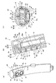
- FIG. 1 is a side view of the shower head which is one Embodiment of this invention.
- (B) is an exploded perspective view of the shower head of (a), (b) is shown from the front side of the head cover, and (c) is shown from the back side of the head cover. It is.
- It is a schematic diagram of the watering plate in the shower head shown to Fig.1 (a)-(c), (a) is a top view, (b) is a front view, (c) is a side view.
- (A) is the principal part perspective view of the shower apparatus provided with the shower head shown in FIG. 1,
- (b) is the sectional view on the AA line of (a),
- (c) is (a).
- FIG. 1A is a side view of a shower head according to an embodiment of the present invention.
- FIGS. 1B and 1C are exploded perspective views of the shower head of FIG. 1A, FIG. 1B is a view from the front side of the head cover, and FIG. 1C is a view from the back side of the head cover.
- FIG. 2 is a schematic view of a watering plate in the shower head shown in FIGS. 1 (a) to 1 (c), (a) is a plan view, (b) is a front view, and (c) is a side view.
- 3 (a) is a perspective view of the main part of the shower device provided with the shower head shown in FIG. 1, and FIG.
- FIG. 3 (b) is a cross-sectional view taken along the line AA in FIG. 3 (a).
- FIG. 3C is a cross-sectional view taken along line BB in FIG.
- the surface of the shower head constituting member that discharges hot water as a shower is the front surface, and the surface that is opposite to the surface that discharges hot water is the back surface.
- the shower head 1 includes a head body 2, a hard head cover 3, and a watering plate 4 having elasticity.
- the head main body 2 has a hot water introduction channel 5 formed therein.
- the head cover 3 can be attached to the front surface side of the head body 2 and has a plate-like portion. In this plate-like portion, a plurality of water spray holes 10 are formed penetrating the front and back.
- the water spray plate 4 can be attached to the back surface 8b of the head cover 3 and has a plate-like portion. On the surface 15 a of the plate-like portion, a plurality of watering protrusions 16 that can be inserted into each one of the watering holes 10 are erected.
- the sprinkling protrusion 16 has a discharge hole 17 at its tip, and a hot water discharge passage 18 is formed through the discharge hole 17 to the back surface 15b of the plate-like portion.
- the plate-like portion of the head cover 3 has a front surface 8a having a curved surface shape and a back surface 8b having a planar shape.
- the plate-like portion has a uniform thickness.
- the plurality of water spray protrusions 16 have a length that protrudes outward from the surface 8 a of the plate-like portion of the head cover 3, and the lengths of the protrusion portions are uniform.
- the foreign matter removing portion 12 for removing the foreign matter around the discharge hole 17 by elastic deformation is formed.
- a shower head 1 includes a head body 2 having a vertically long shape, and a head cover 3 that can be attached to the surface side of the front end portion of the head body 2 in the length direction. And a watering plate 4 that can be attached to the back surface of the head cover 3.
- the shower head 1 is housed in a shower case 41 including a front surface side shower case 42 and a back surface side shower case 43 so that the surface of the head cover 3 is exposed.
- a part of the shower device 40 is configured.
- a hot water introduction passage 5 extending in the length direction is formed inside.
- outflow holes 6 are formed on the surface of the head body 2, and the outflow holes 6 communicate with each other through the introduction flow path 5 and the outflow flow path 7.
- the outflow channel 7 extends in the thickness direction of the head body 2 and is formed inside the head body 2.
- the head main body 2 is provided with a flow path forming portion 30 at two positions adjacent to the front end portion in the length direction and the front end portion.
- the flow path forming part 30 is configured by a cylindrical side wall part 31 and a plate-like flat plate part 32 having a circular shape in plan view.
- Side wall portions 31 of two adjacent flow path forming portions 30 are connected to each other, so that the two flow path forming portions 30 are integrally formed.
- the side wall portions 31 of the two flow path forming portions 30 connected to each other have a snowball shape in plan view.
- the plan view snowman shape means an outer shape in which two circles are partially overlapped and connected. Introduced flow paths 5 shown in FIGS. 3B and 3C are formed inside the two flow path forming portions 30 connected to each other.
- the flat plate part 32 of the flow path forming part 30 is provided on the surface side of the side wall part 31.
- An outflow hole 6 is formed in the center portion of the surface 32 a of the flat plate portion 32.
- a peripheral wall portion 33 protruding from the surface 32 a of the flat plate portion 32 is provided on the entire periphery of the periphery of the surface 32 a of the flat plate portion 32.
- the peripheral wall portion 33 is formed as a part of the side wall portion 31 of the flow path forming portion 30.
- support portions 34 protruding from the surface 32 a of the flat plate portion 32 are arranged at equal intervals at three locations around the outflow hole 6 inside the peripheral wall portion 33.
- the support part 34 has a columnar shape.
- the peripheral wall portion 33 and the support portion 34 constitute a pressing portion 35 that holds the water spray plate 4, and the protruding height is substantially uniform so that the water spray plate 4 can be stably held.
- a head body 2 can be formed from, for example, hard resin, metal, or the like.
- the head cover 3 has a vertically long shape corresponding to the longitudinal end portion of the head body 2 shown in FIG. 3B.
- the head cover 3 has a plate-like portion 8 as a plate-like portion.
- the outer shape of the plate-like portion 8 is a vertically long shape, both ends in the length direction are formed in an arc shape, both sides of the both ends in the width direction are formed in parallel with each other, and have a substantially elliptical shape in plan view.
- the surface 8a of the plate-like portion 8 has a curved surface shape. Specifically, it has a shape warped in a concave shape in the length direction and a shape curved in a convex shape in the width direction.
- the back surface 8b of the plate-like portion 8 has a planar shape. Accordingly, the thickness of the plate-like portion 8 differs depending on the surface shape.
- the surface shape of the plate-like portion 8 of the head cover 3 is not limited to the shape of the present embodiment, and may be various surface shapes such as a convex curved surface shape, a concave curved surface shape, and an uneven curved surface shape from the viewpoint of design. .
- the plate-like portion 8 is provided with watering portions 9 at two locations, that is, a tip portion and a portion adjacent to the tip portion.
- a plurality of circular watering holes 10 are formed so as to penetrate the front and back of the plate-like part 8.
- the watering hole 10 is provided as two rows of the inner side and the outer side, and the row of the watering hole 10 located on the inner side and the row of the watering hole 10 located on the outer side are arranged concentrically.
- the water sprinkling part 9 is provided with a peripheral wall part 11 protruding from the back surface of the plate-like part 8, and the peripheral wall part 11 partitions the water sprinkling part 9 from other parts in the head cover 3.
- the peripheral wall portion 11 has a snowman-like shape in plan view, and is formed so that the flow path forming portion 30 of the head main body 2 can be accommodated in the inside thereof with almost no gap.
- both the part corresponding to the watering part 9 located at the tip part of the plate-like part 8 and the part corresponding to the watering part 9 located in the part adjacent to the tip part of the plate-like part 8 It has a substantially C-shape in plan view and has the same size.
- Such a head cover 3 can be formed from hard resin, metal, etc., and has rigidity.
- the water spray plate 4 has a flat plate portion 15 of a size that fits within the peripheral wall portion 11 provided on the back surface of the head cover 3 with almost no gap as a plate-like portion.
- the shape of the flat plate portion 15 is the same as a snowman shape in plan view as the peripheral wall portion 11.
- the flat plate portion 15 has a uniform thickness throughout, and the thickness is within the height of the peripheral wall portion 11.
- the uniform thickness may include a manufacturing error.
- the difference between the thickness of the thickest portion and the thickness of the thinnest portion is an error of about 10% of the thickness of the thickest portion. Permissible.
- a plurality of watering protrusions 16 having a cylindrical shape are erected on the surface 15 a of the flat plate portion 15.
- the outer diameter of the sprinkling protrusion 16 is substantially the same as the inner diameter of the sprinkling hole 10 formed in the sprinkling part 9 of the head cover 3, and the sprinkling protrusion 16 is the same as the arrangement of the sprinkling holes 10 in the sprinkling part 9 of the head cover 3. It is said that.
- the sprinkling projections 16 are provided on the surface 15a of the flat plate portion 15 as two rows on the inner side and the outer side, and the row of the sprinkling projections 16 located on the inner side and the row of the sprinkling projections 16 located on the outer side are arranged concentrically.
- each of the water spray protrusions 16 can be inserted into each of the water spray holes 10.
- the projection length of the water sprinkling protrusion 16 has a length exceeding a certain amount of the thickness of the plate-like portion 8 in which the corresponding water sprinkling hole 10 is formed.
- the plurality of water spray protrusions 16 provided on the flat plate portion 15 are formed with different protrusion lengths according to the surface shape of the plate-like portion 8 of the head cover 3 corresponding to the arrangement position.
- the protrusion length of the water spray protrusion 16 can be defined as the length from the surface 15a of the flat plate portion 15 to the tip of the water spray protrusion 16.
- a portion of the sprinkling protrusion 16 that protrudes outward from the surface 8 a of the plate-like portion 8 is formed as the foreign matter removing portion 12 as described later.
- the water spray protrusion 16 has a discharge hole 17 at the tip, and in the water spray plate 4, as shown in FIGS. 3B and 3C, hot water penetrating from the discharge hole 17 to the back surface 15 b of the flat plate portion 15.
- a discharge flow path 18 is formed.
- the inner diameter of the portion located on the back surface side of the flat plate portion 15 in the discharge flow path 18 is enlarged toward the back surface 15 b of the flat plate portion 15, thereby forming the expanded diameter portion 19.
- the enlarged diameter portion 19 makes it easy to introduce hot water into the discharge flow path 18.
- Such a watering plate 4 can be formed from rubber
- the water spray plate 4 is formed by inserting each water spray protrusion 16 into each one of the water spray holes 10 formed in the water spray portion 9 of the head cover 3. It is attached to the back of the. In the mounted state, the surface 15 a of the flat plate portion 15 of the water spray plate 4 overlaps the back surface 8 b of the plate-like portion 8 of the head cover 3, and the water spray plate 4 has elasticity, so that the flat plate portion 15 is inside the peripheral wall portion 11. Fits almost without gaps. The mounting state of the water spray plate 4 to the head cover 3 is stably maintained by the rigid head cover 3 and the elasticity of the water spray plate 4.
- the tip end portion of the water spray protrusion 16 inserted into the water spray hole 10 protrudes outward from the surface 8 a of the plate-like portion 8 of the head cover 3, and this protrusion portion forms the foreign matter removing portion 12.
- the length of the protruding portion of the sprinkling protrusion 16 that forms the foreign matter removing portion 12 is uniform for the plurality of sprinkling protrusions 16.
- the uniform length of the protruding portions of the sprinkling protrusions 16 is not construed as being limited to the meaning that the lengths of the protruding portions of all the sprinkling protrusions 16 are the same. Variations in the length of the protruding portion between the water sprinkling protrusions 16 to such an extent that the design of the surface of the head cover 3 is not impaired are allowed.
- the difference between the length of the protruding portion of the sprinkling protrusion 16 having the longest protruding portion length and the length of the protruding portion of the sprinkling protrusion 16 having the shortest protruding portion length is the water sprinkling length of the protruding portion. Variations within 10% of the length of the protruding portion of the protrusion 16 are also allowed.
- the length of the protruding portion can be defined as the length from the center of the water spray hole 10 on the virtual surface of the plate-like portion 8 where the water spray hole 10 is formed to the tip of the water spray protrusion 16 in the length direction. .
- the head cover 3 is attached to the front surface side of the head body 2 in such a state that the watering plate 4 is attached to the back surface 8b of the plate-like portion 8.
- the attachment can be realized by fitting, fixing using a fixing tool such as a screw, and the like, and watertightness can be enhanced by interposing an O-ring or the like.
- the side wall portion 31 of the flow path forming portion 30 of the head main body 2 is fitted inside the peripheral wall portion 11 with almost no gap.
- the back surface 15 b of the flat plate portion 15 of the water spray plate 4 is pressed by the peripheral wall portion 33 constituting the pressing portion 35 and the distal end portion of the support portion 34.
- the surface 15a of the flat plate portion 15 of the water spray plate 4 is in close contact with the back surface 8b of the plate-like portion 8 of the head cover 3, and the water spray plate 4 can be held more stably.
- the attachment state of the water spray plate 4 to the head cover 3 can be made more reliable.
- a hot water inflow channel 14 is formed.
- the inflow channel 14 communicates with the introduction channel 5 through the outflow hole 6 and the outflow channel 7.
- the discharge flow path 18 communicates with the inflow flow path 14 through the enlarged diameter portion 19, and the introduction flow path 5 of the head body 2 communicates with the discharge holes 17 of the water spray protrusions 16. Therefore, the shower head 1 can eject the hot water introduced into the introduction flow path 5 from each discharge hole 17 as a shower.
- the shower head 1 As the shower head 1 is used, clogging may occur in the discharge flow path 18 of the sprinkling protrusions 16 due to foreign matters such as scale caused by calcium in the water component.
- the foreign matter is removed or crushed by applying an external force to the foreign matter removing portion 12 by elastically deforming the foreign matter removing portion 12 by, for example, rubbing the watering projection 16 protruding outward from the surface 8a of the plate-like portion 8 with a finger. Or In this way, foreign matter can be easily removed without disassembling the shower head 1 and removing the watering plate 4.
- foreign matter may adhere to and accumulate in the vicinity of the discharge hole 17, for example, in the water spray hole 10 of the head cover 3.
- the foreign matter can be taken out by applying an external force to the foreign matter removing portion 12 by elastically deforming it by rubbing the sprinkling projection 16 with a finger or by elastically deforming the water spray plate 4 through the sprinkling projection 16. It is possible to easily remove foreign matters such as crushing or crushing.
- the sprinkling protrusion 16 has a length that protrudes outward from the surface 8a of the plate-like portion 8 of the head cover 3, and the protruding portion forms the foreign matter removing portion 12, so that maintenance such as clogging can be performed. Easy.
- the foreign substance removing unit 12 preferably has a length of 0.5 to 2 mm. The foreign substance removing unit 12 having such a length can more easily remove foreign substances.
- the surface 8a of the plate-like portion 8 of the head cover 3 has a curved surface shape that can correspond to various surface shapes such as a convex curved surface shape, a concave curved surface shape, and a concave and convex curved surface shape, it can meet a design requirement. it can. Therefore, it is not limited to a cylindrical shower head as described in Patent Document 1, and can be designed in various shapes, and is versatile. Moreover, since the length of the protruding portion of the sprinkling protrusion 16 protruding outward from the surface 8a of the plate-like portion 8 of the head cover 3 is made uniform, the design of the surface of the head cover 3 is not impaired and the shower has a good appearance. The head 1 can be obtained.
- the watering plate 4 Since the flat plate portion 15 of the watering plate 4 has a uniform thickness, the watering plate 4 can be easily designed and manufactured.
- the water spray plate 4 having a uniform thickness of the flat plate portion 15 can be used in combination with various head covers 3 having different surface shapes, and the shower head 1 can be easily designed and manufactured.
- FIG. 4 is an enlarged cross-sectional view of the vicinity of a water spray hole of a head cover of a shower head according to another embodiment of the present invention. 4, the same parts as those in the embodiment shown in FIGS. 1 to 3 are denoted by the same reference numerals, and the description thereof is omitted.
- the shower head 50 can also incline a part of the side surface 21 of the watering hole 10 formed in the watering part 9 of the head cover 51 inward.
- the slope of the side surface 21 is inserted into the water spray hole 10, and the water spray protrusion 16 protruding outward from the surface of the plate-like portion 8 of the head cover 51 is located outward of the water spray portion 9 toward the downstream side, that is, outside the head cover 51. It is said that the direction is inclined.
- Such an inclination of the side surface 21 regulates the arrangement of the sprinkling protrusions 16.
- the inclination of the side surface 21 can be provided in all or part of the water spray hole 10.
- the shower head 50 since a part of the side surface 21 of the water spray hole 10 is inclined as described above, the water spray protrusion 16 inserted into the water spray hole 10 is inclined in the inclination direction of the side surface 21, and the arrangement is restricted. . For this reason, as shown in FIG. 4, the sprinkling range R of hot water discharged from the discharge holes 17 of the sprinkling protrusions 16 extends outward of the head cover 51. Therefore, even if the shower head 50 is comparatively small, the watering range R required for the shower function can be realized.
- the head cover 51 is hard and has high dimensional accuracy in manufacturing, even if the dimensions of the sprinkling plate 4 having elasticity vary, the expansion of the sprinkling range R can be stably performed without being greatly affected by the variation. Can be realized.
- the inclination of the side surface 21 of the water sprinkling hole 10 can be formed by the protrusion 22 which protrudes inside the sprinkling hole 10, for example, as shown in FIG.
- the protrusion 22 can easily form the slope of the side surface 21.
- Examples of the shape of the protrusion 22 include an arc shape or an arc shape along the inner periphery of the water spray hole 10.
- the inclination angle ⁇ 1 is larger than the inclination angle ⁇ 2. That is, the relation ⁇ 1> ⁇ 2 is established.
- the amount of hot water discharged from the 16 discharge holes 17 can be secured.
- a comfortable shower feeling can be given to the user who uses the shower head 50, and it is effective in enhancing the cleaning power by the shower.
- the magnitudes of the inclination angles ⁇ 1 and ⁇ 2 can be appropriately determined according to the size and specific application of the shower head 50, the projection length of the water spray projection 16, and the like.
- the present invention is not limited to the above embodiment. Various modes are possible for the shape and size of the head main body, head cover, and watering plate, and the type of material forming them.
Landscapes
- Bathtubs, Showers, And Their Attachments (AREA)
- Nozzles (AREA)
Abstract
L'invention concerne une pomme de douche (1) qui peut être aisément réparée en cas d'obstruction, peut répondre aux exigences de conception et peut faciliter la conception et la production d'une plaque d'arrosage. La pomme de douche (1) comprend une unité de pomme (2), un couvercle de pomme rigide (3) et une plaque d'arrosage (4) présentant une certaine élasticité. A l'intérieur du couvercle de pomme (3), une pluralité de trous d'arrosage (10) sont formés dans une section en forme de plaque (8). La section en forme de plaque (8) comporte une surface avant (8a) de forme bombée et une surface arrière (8b) de forme plane. Une pluralité de protubérances d'arrosage (16) pouvant être insérées dans les trous d'arrosage (10) font saillie à partir de la surface avant (15a) d'une section en forme de plaque (15) sur la plaque d'arrosage (4). La section en forme de plaque (8) comporte une surface avant (8a) de forme bombée et une surface arrière (8b) de forme plane. Les protubérances d'arrosage (16) comportent des trous de pulvérisation (17) au niveau de leurs extrémités distales et des passages de pulvérisation (18) pour l'eau chaude qui s'étendent à partir des trous de pulvérisation (17) jusqu'à la surface arrière (15b) de la section en forme de plaque (15). Les protubérances d'arrosage (16) présentent une longueur suffisante pour faire saillie vers l'extérieur à partir de la surface avant (8a) de la section en forme de plaque (8) du couvercle de pomme (3), les sections protubérantes étant de longueur uniforme et formant des parties d'élimination de matières étrangères (12).
Applications Claiming Priority (2)
| Application Number | Priority Date | Filing Date | Title |
|---|---|---|---|
| JP2013122130A JP6315364B2 (ja) | 2013-06-10 | 2013-06-10 | シャワーヘッド |
| JP2013-122130 | 2013-06-10 |
Publications (1)
| Publication Number | Publication Date |
|---|---|
| WO2014199625A1 true WO2014199625A1 (fr) | 2014-12-18 |
Family
ID=52021938
Family Applications (1)
| Application Number | Title | Priority Date | Filing Date |
|---|---|---|---|
| PCT/JP2014/003072 Ceased WO2014199625A1 (fr) | 2013-06-10 | 2014-06-09 | Pomme de douche |
Country Status (2)
| Country | Link |
|---|---|
| JP (1) | JP6315364B2 (fr) |
| WO (1) | WO2014199625A1 (fr) |
Families Citing this family (2)
| Publication number | Priority date | Publication date | Assignee | Title |
|---|---|---|---|---|
| JP6656581B2 (ja) * | 2015-12-15 | 2020-03-04 | Toto株式会社 | 吐水装置 |
| US12017235B2 (en) | 2018-12-21 | 2024-06-25 | J. Wagner Gmbh | Atomiser system having a silicone nozzle array |
Citations (3)
| Publication number | Priority date | Publication date | Assignee | Title |
|---|---|---|---|---|
| WO2006035792A1 (fr) * | 2004-09-29 | 2006-04-06 | Toto Ltd. | Pomme de douche |
| JP2008012413A (ja) * | 2006-07-04 | 2008-01-24 | Toto Ltd | シャワーヘッド |
| JP2012135606A (ja) * | 2010-12-07 | 2012-07-19 | Lixil Corp | シャワー吐水装置 |
Family Cites Families (4)
| Publication number | Priority date | Publication date | Assignee | Title |
|---|---|---|---|---|
| JP2004105649A (ja) * | 2002-09-20 | 2004-04-08 | Toto Ltd | シャワーノズル |
| JP2004105650A (ja) * | 2002-09-20 | 2004-04-08 | Toto Ltd | シャワーノズル |
| JP5344370B2 (ja) * | 2009-01-13 | 2013-11-20 | Toto株式会社 | シャワーヘッド |
| JP5365993B2 (ja) * | 2009-03-25 | 2013-12-11 | Toto株式会社 | シャワーヘッド |
-
2013
- 2013-06-10 JP JP2013122130A patent/JP6315364B2/ja active Active
-
2014
- 2014-06-09 WO PCT/JP2014/003072 patent/WO2014199625A1/fr not_active Ceased
Patent Citations (3)
| Publication number | Priority date | Publication date | Assignee | Title |
|---|---|---|---|---|
| WO2006035792A1 (fr) * | 2004-09-29 | 2006-04-06 | Toto Ltd. | Pomme de douche |
| JP2008012413A (ja) * | 2006-07-04 | 2008-01-24 | Toto Ltd | シャワーヘッド |
| JP2012135606A (ja) * | 2010-12-07 | 2012-07-19 | Lixil Corp | シャワー吐水装置 |
Also Published As
| Publication number | Publication date |
|---|---|
| JP6315364B2 (ja) | 2018-04-25 |
| JP2014236926A (ja) | 2014-12-18 |
Similar Documents
| Publication | Publication Date | Title |
|---|---|---|
| US7055767B1 (en) | Shower head structure | |
| US20070252021A1 (en) | Shower Head | |
| US7721979B2 (en) | Shower spray device | |
| USD568633S1 (en) | Dresser | |
| US8807461B2 (en) | Shower head | |
| JP2012152470A (ja) | シャワー吐水装置 | |
| JP6315364B2 (ja) | シャワーヘッド | |
| KR20170028765A (ko) | 청소기 | |
| JP2010162436A (ja) | シャワーヘッド | |
| JP4057555B2 (ja) | 平板ディスプレイ表面処理用流体噴射装置 | |
| MY136755A (en) | Microstructured high pressure nozzle with built-in filter function | |
| JP2017113282A5 (fr) | ||
| JP2008012413A (ja) | シャワーヘッド | |
| JP5365993B2 (ja) | シャワーヘッド | |
| EP2449931B1 (fr) | Plaque de pulvérisation d'eau | |
| JP5505622B2 (ja) | シャワー装置 | |
| JP6115761B2 (ja) | シャワーヘッド | |
| DE502007000095D1 (de) | Zwischenwirbelimplantat | |
| JP6343919B2 (ja) | シャワーヘッド | |
| JP2015146829A (ja) | シャワーヘッド | |
| CN111389606B (zh) | 具有喷射盘保持设备的淋浴头 | |
| JP6343918B2 (ja) | シャワーヘッド | |
| KR200481324Y1 (ko) | 샤워호스용 설치유도 부재 | |
| JP2006122192A (ja) | 簡易ビデ | |
| USD561635S1 (en) | Bracelet |
Legal Events
| Date | Code | Title | Description |
|---|---|---|---|
| 121 | Ep: the epo has been informed by wipo that ep was designated in this application |
Ref document number: 14810375 Country of ref document: EP Kind code of ref document: A1 |
|
| NENP | Non-entry into the national phase |
Ref country code: DE |
|
| 122 | Ep: pct application non-entry in european phase |
Ref document number: 14810375 Country of ref document: EP Kind code of ref document: A1 |