WO2014199635A1 - Dispositif de génération de force de propulsion - Google Patents
Dispositif de génération de force de propulsion Download PDFInfo
- Publication number
- WO2014199635A1 WO2014199635A1 PCT/JP2014/003108 JP2014003108W WO2014199635A1 WO 2014199635 A1 WO2014199635 A1 WO 2014199635A1 JP 2014003108 W JP2014003108 W JP 2014003108W WO 2014199635 A1 WO2014199635 A1 WO 2014199635A1
- Authority
- WO
- WIPO (PCT)
- Prior art keywords
- main body
- flange
- cylindrical housing
- propulsion device
- fixed flange
- Prior art date
- Legal status (The legal status is an assumption and is not a legal conclusion. Google has not performed a legal analysis and makes no representation as to the accuracy of the status listed.)
- Ceased
Links
Images


Classifications
-
- B—PERFORMING OPERATIONS; TRANSPORTING
- B63—SHIPS OR OTHER WATERBORNE VESSELS; RELATED EQUIPMENT
- B63H—MARINE PROPULSION OR STEERING
- B63H1/00—Propulsive elements directly acting on water
- B63H1/02—Propulsive elements directly acting on water of rotary type
- B63H1/12—Propulsive elements directly acting on water of rotary type with rotation axis substantially in propulsive direction
- B63H1/14—Propellers
- B63H1/16—Propellers having a shrouding ring attached to blades
- B63H2001/165—Hubless propellers, e.g. peripherally driven shrouds with blades projecting from the shrouds' inside surfaces
-
- B—PERFORMING OPERATIONS; TRANSPORTING
- B63—SHIPS OR OTHER WATERBORNE VESSELS; RELATED EQUIPMENT
- B63H—MARINE PROPULSION OR STEERING
- B63H23/00—Transmitting power from propulsion power plant to propulsive elements
- B63H23/22—Transmitting power from propulsion power plant to propulsive elements with non-mechanical gearing
- B63H23/24—Transmitting power from propulsion power plant to propulsive elements with non-mechanical gearing electric
Definitions
- the present invention relates to a thrust generator for generating a propulsive force for a ship or the like.
- a propulsion device (hereinafter also referred to as “rim drive propulsion device”) in which a propeller is disposed on the inner periphery of a rotor of a ring-shaped electric motor and the electric motor and the propeller are integrated is attracting attention. Yes.
- the propeller since the propeller is disposed on the inner periphery of the rotor of the electric motor, cavitation generated from the propeller blade tip can be suppressed. Therefore, the efficiency is improved, cavitation noise can be reduced, and low noise and vibration can be reduced.
- a seawater lubricated bearing is adopted as a bearing that supports the propeller blades, even if the propulsion unit is damaged, there is no problem of oil leakage, which can contribute to reducing the environmental load in the marine field.
- a rotor of a ring-shaped electric motor is provided with a propeller blade that protrudes inward in the radial direction, and a propellant blade that is driven by the motor is rotated to inject water flow in the axial direction to generate a propulsive force.
- thrust generators see, for example, Patent Documents 1 and 2). These thrust generators are provided, for example, in arrangement holes (tunnels) that penetrate in the horizontal direction of the hull provided at the bow or stern of the hull so that the propeller blades and the like can be disassembled. All propeller blades are connected to a boss located in the center of the rotor.
- an object of the present invention is to provide a thrust generator with good maintainability that can be integrally removed from a ship with a propeller blade or the like as a propeller main body.
- a thrust generator of the present invention is a thrust generator that is disposed in a liquid and generates a thrust by injecting the liquid, and includes a cylindrical housing that is open on both sides in the axial direction.
- a propulsion device body including an annular stator disposed inside the cylindrical housing, an annular rotor disposed inside the stator, and propeller blades provided on an inner peripheral surface of the rotor; and the propulsion device A pair of fairings that are detachably attached to both side surfaces of the main body and expand from the position corresponding to the inner peripheral surface of the rotor toward the cylindrical housing, and the cylindrical housing is radially inward. It has a fixed flange protruding in the direction, and the propeller main body is detachably attached to the fixed flange by a fastening member.
- the propulsion device main body and the cylindrical housing can be separated by removing the fastening member. Therefore, the propulsion device main body can be pulled out from the cylindrical housing in the axial direction for maintenance, and the maintainability can be improved. Therefore, the structure of the propeller blades and the like can be easily removed and inspected as a propeller main body even during maintenance inspection of the propeller blades and the like.
- the propulsion device main body may have a connecting portion that overlaps the fixed flange in the axial direction of the cylindrical housing, and the fastening member may be a bolt that penetrates the connecting portion or the fixed flange. If comprised in this way, when a fairing is removed from a propeller main body, a volt
- the cylindrical housing may have a support flange that supports the propulsion device main body at a position away from the fixed flange in the axial direction. If comprised in this way, the attitude
- the fixing flange may have a liquid passing portion that allows a cooling liquid to flow to an outer peripheral portion of the propulsion device main body in a state where the propulsion device main body is attached to the fixing flange. If comprised in this way, since a cooling fluid will flow into the outer peripheral part of a propulsion device main body through the liquid flow part of a fixed flange, a propulsion device main body can be cooled efficiently. Accordingly, the efficiency of the propulsion device can be improved by appropriately cooling the motor portion that rotates the propeller blades.
- the fixed flange is continuous in the circumferential direction, and the propulsion device main body has a ring-shaped connecting portion that overlaps the fixed flange in the axial direction of the cylindrical housing, and the fixed flange includes the liquid passing portion.
- a plurality of flow holes may be provided in a region where the fixed flange and the connection part overlap, and the connection part may have a plurality of flow holes at a position that coincides with the flow hole. If comprised in this way, a cooling fluid can be flowed in into an outer peripheral part of a propulsion device main body, or a cooling liquid can be flowed out from an outer peripheral part so that the connection part and fixed flange of a propulsion device main body may be penetrated.
- the cylindrical housing has a support flange that supports the propulsion unit main body at a position axially away from the fixed flange, and the support flange causes the coolant to flow to an outer peripheral portion of the propulsion unit main body. It may have a liquid passing part which enables.
- the coolant that has flowed into the outer peripheral part of the propulsion unit main body from the liquid passing part of the fixed flange or the support flange in the circumferential direction at the outer peripheral part of the propulsion unit main body is formed. According to this configuration, the coolant flowing into the outer peripheral portion of the propulsion device main body from the liquid passing portion of the fixed flange or the support flange is allowed to flow in the circumferential direction of the propulsion device main body, so that the outer peripheral portion of the propulsion device main body is efficiently It can cool well.
- the fluid passage portion of the fixed flange and the fluid passage portion of the support flange are disposed within a partial range in the circumferential direction, and the cylindrical housing forms a flow path between the fixed flange and the support flange.
- the flow path forming member may have an opening at a position opposite to the liquid passing portion of at least one of the fixed flange and the support flange across the axis of the cylindrical housing. If comprised in this way, the cooling fluid which flowed into the outer peripheral part of the propulsion unit main body from one liquid passing part of a fixed flange and a support flange will be carried out in the circumferential direction of a propulsion unit main body by the flow path formed of the flow path formation member.
- this cooling liquid flows out from the other liquid passing part of the fixed flange and the supporting flange, a long cooling flow path can be formed in the outer peripheral part of the propulsion device main body, so that the cooling can be performed more efficiently.
- the cooling efficiency can be increased by setting the flow path cross-sectional area so that the flow rate of the coolant is increased.
- the thrust generator includes a power cable connected from the cylindrical housing to the stator, a waterproof tube provided between the cylindrical housing and the propulsion device body, and through which the power cable is inserted, May be further provided. If comprised in this way, the power cable can be kept waterproof by the waterproof tube during operation, and the power cable can be removed by removing the waterproof tube when removing the propulsion unit main body.
- the thrust generation device further includes a power cable connected from the cylindrical housing to the stator, and the power cable is watertight and detachable in water between the cylindrical housing and the propeller main body.
- An underwater connector may be included. If comprised in this way, when removing a propeller main body, an electric power cable can be easily cut off in the part of an underwater connector.
- the present invention can be attached to a ship or the like, and can be easily removed and integrally maintained with the propeller main body at the time of maintenance of the propeller blade, etc., and it is possible to constitute a thrust generator with high maintainability. Become.
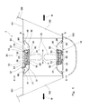
- FIG. 1 is a longitudinal sectional view showing a thrust generator according to a first embodiment of the present invention.
- FIG. 2 is a front view taken along the line II-II shown in FIG.
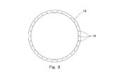
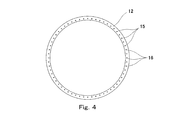
- FIG. 3 is a front view of the support flange shown in FIG. 4 is a front view of the fixing flange shown in FIG.
- FIG. 5 is a schematic diagram for explaining a water flow in a flange portion of the thrust generator shown in FIG.
- FIG. 6 is a longitudinal sectional view when the thrust generator shown in FIG. 1 is disassembled.
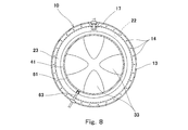
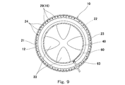
- FIG. 9 is a cross-sectional view taken along the line IX-IX shown in FIG.
- FIG. 10 is a longitudinal sectional view showing a thrust generating apparatus according to the third embodiment of the present invention.
- FIG. 11 is a longitudinal sectional view showing a thrust generator according to a fourth embodiment of the present invention.
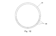
- FIG. 12 is a front view of the support flange shown in FIG.
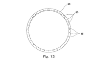
- FIG. 13 is a front view of the fixing flange shown in FIG.
- FIG. 14 is a front view of the flow path forming flange shown in FIG. 11 by the arrow XIV-XIV.
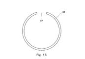
- FIG. 15 is a front view of the flow path forming flange indicated by arrows XV-XV in FIG.
- FIG. 16 is a schematic diagram for explaining the water flow in the flange portion of the thrust generator shown in FIG. It is a longitudinal cross-sectional view which shows a part of thrust generating apparatus which concerns on a 1st modification. It is a longitudinal cross-sectional view which shows a part of thrust generating apparatus which concerns on a 2nd modification. It is a longitudinal cross-sectional view which shows a part of thrust generating apparatus which concerns on a 3rd modification. It is a longitudinal cross-sectional view which shows a part of thrust generating apparatus which concerns on a 4th modification.
- a thrust generator provided in a cylindrical wall (tunnel) penetrating in the horizontal direction of the hull provided at the bow or stern of the hull and used for a side thruster of the ship will be described as an example. That is, the thrust generator is disposed in water.
- the thrust generator 1 of this embodiment is provided on a cylindrical wall 101 provided in a hull 100, and thrusts by injecting water W horizontally from both openings 102 of the cylindrical wall 101. Is supposed to occur.
- the central portion of the cylindrical wall 101 is an arrangement portion 103, and a cylindrical housing 10 that is open on both sides in the axial direction is fixed to the arrangement portion 103.
- the cylindrical wall 101 is divided into a pair of short pipes that are separated from each other in the horizontal direction of the hull, and the arrangement portion 103 is configured by a gap between these short pipes.
- the cylindrical housing 10 is formed to have the same inner diameter as the cylindrical wall 101 and is fixed to the cylindrical wall 101 by welding or the like.
- the axial direction of the cylindrical housing 10 may be referred to as a left-right direction (a surface facing the direction is a side surface).
- a propeller main body 20 is disposed inside the cylindrical housing 10.
- two flanges 12 and 13 projecting radially inward are provided at predetermined positions on the inner peripheral surface of the cylindrical housing 10.
- a fixing flange 12 for fixing the propulsion device main body 20 is provided on the right side in the drawing, and a support flange 13 for supporting the propulsion device main body 20 is provided on the left side in the drawing.
- These flanges 12 and 13 are arranged apart from each other in the axial direction X of the plurality of propeller blades 33 (also the axial direction of the cylindrical housing 10), and are equidistant from the center of the propeller blades 33 in the axial direction X. It is arranged at the position.
- the flanges 12 and 13 may be appropriately arranged according to the size of the propulsion device main body 20 and the like.
- the distance between the side surfaces of the fixed flange 12 and the support flange 13 facing each other is 0.2 times or more the diameter of the propeller constituted by the propeller blades 33.
- both the fixed flange 12 and the support flange 13 are continuous in the circumferential direction.
- the cylindrical housing 10 should just have at least 1 flange (only the fixed flange 12), and the fixed flange 12 and support are provided.
- the total number of flanges 13 may be three or more.
- a configuration having the function of the support flange 13 may be provided so as to protrude from the propulsion device main body 20.
- a configuration as shown in FIG. 19 is adopted so that the propulsion device main body 20 is pulled out from the cylindrical housing 10 to the left side.
- the propulsion device main body 20 is pulled out from the cylindrical housing 10 to the right side.
- the propulsion device main body 20 is disposed on the inner side of the cylindrical housing 10 and on the inner side of the outer peripheral casing 22.
- An annular stator 25 and a pair of annular side casings 23 fixed to both side surfaces of the outer casing 22 are provided.
- the stator 25 is disposed in an annular groove that is formed by the outer casing 22 and the side casing 23 and opens radially inward.
- the outer peripheral casing 22 is a cylindrical body that is longer than the distance between the side surfaces of the fixing flange 12 and the support flange 13 that face each other.
- a connecting portion 21 that overlaps the fixing flange 12 in the axial direction X is provided at one end (right side) of the outer peripheral casing 22 so as to protrude outward in the radial direction.
- the connection part 21 is a ring shape which continues in the circumferential direction.
- the connecting portion 21 is fixed to the fixing flange 12 by a fixing bolt 24 (an example of a fastening member of the present invention) in contact with the right side surface (side surface opposite to the support flange 13) of the fixing flange 12. That is, the propulsion device main body 20 is detachably attached to the fixing flange 12 by the fixing bolt 24 that penetrates the connecting portion 21.
- the outer peripheral surface of the outer casing 22 is supported by the inner peripheral surface of the support flange 13.
- the power cable 27 penetrates the side casing 23 provided in the opposite direction (left side) to the connecting portion 21.
- the power cable 27 is connected from the cylindrical housing 10 to the armature coil 26 of the stator 25.
- the stator 25 is provided with a plurality of armature coils 26 and is formed in an annular shape.
- the power cable 27 is inserted into a waterproof tube 17 provided between the cylindrical housing 10 and the side casing 23.
- the waterproof tube 17 is fixed to the cylindrical housing 10, and an end is attached to the side casing 23 with a bolt or the like.
- An annular rotor 30 is disposed inside the stator 25.
- the rotor 30 has a rotor core 31 formed in an annular shape with a plurality of magnets attached thereto, and an annular rotor body 32 in which the rotor core 31 is fitted.
- the rotor 30 is rotated by a rotor core 31 that is rotated by supplying power to the armature coil 26 of the stator 25.
- the rotation speed, the rotation direction, and the like of the rotor core 31 can be changed.
- the stator 25 is adapted to transfer heat to the outer casing 22 by heat conduction.
- the stator 25 and the rotor 30 constitute an electric motor.
- the stator 25 is cooled by convection cooling outside the outer casing 22 (that is, the outer peripheral portion of the propulsion device main body 20). It has become.
- a propeller blade 33 is provided on the inner peripheral surface of the rotor body 32. These propeller blades 33 are formed in a shape capable of generating thrust even when rotating in either the forward direction or the reverse direction.
- the propeller blade 33 has a base attached to the rotor body 32. Therefore, the occurrence of cavitation by the propeller blade 33 can be suppressed. Therefore, noise and vibration caused by cavitation can be reduced.
- the propeller blade 33 has a tip positioned near the center of the rotor 30, and a central opening (see FIG. 2) is defined at the center of the rotor 30 by the tips of all the propellers.
- a plurality of propeller blades 33 in this embodiment are provided at equal intervals in the circumferential direction (in this example, four as will be described later).
- the rotor 30 is supported by water-lubricated bearings 50 and 51 provided on the inner peripheral edge of the side casing 23.
- the rotor body 32 is provided with collar portions 34 and 35 extending on both sides in the axial direction X from the central portion where the rotor core 31 is provided.
- the inner peripheral surface 52 of the water-lubricated bearings 50 and 51 supports a radial load acting in the radial direction of the rotor body 32 by forming a water film between the outer peripheral surfaces of the collar portions 34 and 35.
- the water-lubricated bearings 50 and 51 have opposing surfaces 53 with both side surfaces in the axial direction X of the rotor body 32 (annular surfaces extending radially outward from the roots of the collar portions 34 and 35).
- a thrust film acting in the axial direction of the rotor main body 32 is supported by forming a water film between the both side surfaces and the opposing surface 53.
- the inner peripheral surface 52 is a radial bearing surface
- the facing surface 53 is a thrust bearing surface.
- the water-lubricated bearings 50 and 51 are provided so as to sandwich the rotor body 32 from the axial direction X, and the radial load and thrust load acting on the rotor 30 are supported by these water-lubricated bearings 50 and 51. Yes.
- the water-lubricated bearings 50 and 51 are sliding bearing systems. Further, water W flows from the facing surface 53 to a gap between the rotor core 31 and the stator 25. Such water-lubricated bearings 50 and 51 do not cause a problem of oil leakage.
- a pair of fairings 40 and 41 are provided in which the collar portions 34 and 35 are connected to the inner peripheral surface.
- These fairings 40 and 41 extend while expanding in diameter in a direction away from the rotor 30. More specifically, the fairings 40 and 41 expand toward the cylindrical housing 10 from a position corresponding to the inner peripheral surface of the rotor 30 (in this embodiment, a position that forms a continuous surface with the inner peripheral surface of the rotor 30). The diameter is formed so that the end is close to the inner periphery of the cylindrical housing 10.
- fairings 40 and 41 are formed so as to extend from the position of the water-lubricated bearings 50 and 51 to the axial end of the cylindrical housing 10 (near the boundary of the arrangement portion 103). These fairings 40 and 41 are detachably attached to the water-lubricated bearings 50 and 51 constituting both side surfaces of the propulsion device body 20 with bolts (not shown).
- a fairing 41 is provided with a predetermined gap S from the cylindrical housing 10 (the same applies to the fairing 40).
- Propeller blades 33 are located at the center of the fairing 41 (40). In this example, there are four propeller blades 33, and the central portion of the propeller blade 33 is a space.
- the support flange 13 is provided with a plurality of flow holes (fluid passages) 14 in the circumferential direction.
- the plurality of flow holes 14 allow water W to flow through the support flange 13.
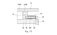
- the fixing flange 12 is provided with a plurality of fixing holes (screw holes having female threads) 15 and flow holes (liquid passage portions) 16 alternately on the entire circumference.
- the fixing holes 15 are provided at an equal pitch in the circumferential direction, and through holes 16 are provided at an equal pitch between the fixing holes 15.
- the fixing bolt 24 is screwed into the fixing hole 15. That is, the flow hole 16 is provided in a region where the fixing flange 12 and the connecting portion 21 overlap.
- the plurality of flow holes 16 allow water W to flow through the fixed flange 12.
- the same number of flow holes 14 and 16 are provided in the fixed flange 12 and the support flange 13.
- the through holes 14 and 16 are for allowing water W to flow to the outer peripheral portion of the propulsion device main body 20 in a state where the propulsion device main body 20 is attached to the fixed flange 12.
- FIG. 5 is a drawing of a state in which the propulsion device main body 20 is attached to the fixed flange 12.
- the outer peripheral casing 22 of the propulsion unit body 20 has a portion in contact with the fixed flange 12 and a portion in contact with the support flange 13 formed in the large diameter portion 45 by a width corresponding to the plate thickness of the flanges 12 and 13.
- the small diameter portion 46 is formed. Further, the large diameter portion 45 continues to the small diameter portion 46 with a tapered surface. This increases the clearance (clearance) between the fixed flange 12 and the support flange 13 and the outer casing 22 when the propulsion device body 20 is moved in the axial direction X, and facilitates the movement of the propulsion device main body 20 in the axial direction X. ing.
- the connecting portion 21 of the propulsion device main body 20 is brought into contact with the right side surface of the fixed flange 12.
- the propulsion device main body 20 is fixed by inserting the fixing bolt 24 into the bolt insertion hole 28 provided in the connecting portion 21 and screwing it into the fixing hole (screw hole having a female screw) 15 provided in the fixing flange 12. It is fixed to the flange 12.
- the propulsion device main body 20 is fixed by surface pressure of a contact surface between the connecting portion 21 and the fixing flange 12 generated by fastening the connecting portion 21 to the fixing flange 12 with a fixing bolt 24. In the figure, only one of the fixing bolts 24 provided in the circumferential direction is shown.
- the small-diameter portion 46 is formed except for the portion corresponding to the plate thickness of the support flange 13 and the portion corresponding to the plate thickness of the fixed flange 12 as described above. Until then, it is easy to move in the axial direction X with a large gap.
- flow holes 14 and 16 are provided in the fixed flange 12 and the support flange 13.
- the connecting portion 21 is provided with a plurality of flow holes (fluid portions) 29 at positions corresponding to the flow holes 16 of the fixed flange 12. Therefore, as shown in the figure, the flow holes 16 and 29 are communicated with each other in a state where the connecting portion 21 is fixed to the fixing flange 12.
- a cooling flow path 90 for water cooling the outer casing 22 is formed between the outer casing 22 between the fixed flange 12 and the support flange 13 and the cylindrical housing 10.
- the propulsion device when the propeller blade 33 is rotated and a water flow is generated, the propulsion device is generated from the gap S (FIG. 1) between the cylindrical housing 10 and one of the fairings 40 and 41.
- Water W (coolant) flows into the main body 20, and the water W flows through the cooling channel 90.
- the propulsion device main body 20 injects the water W to the left side, the water W passes through the through holes 29 and 16 provided in the connecting portion 21 and the fixing flange 12, and the outer casing 22 and the cylindrical housing 10. And flows between the outer casing 22 and the cylindrical housing 10 and then flows out through the flow holes 14 provided in the support flange 13.
- the flow of the water W along the cooling flow path 90 is caused by the flow of the water W injected to one side from the opening 102 of the cylindrical wall 101 by rotating the propeller blade 33.
- the flow of water W occurs in either the left or right direction depending on the rotation direction of the propeller blades 33.
- FIG. 6 is a drawing when the thrust generator 1 according to the first embodiment is disassembled.
- the fairings 40 and 41 fixed to the water-lubricated bearings 50 and 51 with bolts (not shown) are removed.
- the fairings 40 and 41 can be taken out in the axial direction X from the opening 102 of the cylindrical wall 101 by removing the bolts.
- the fixing bolt 24 that fixes the connecting portion 21 of the propeller main body 20 to the fixing flange 12 is removed. Further, the power cable 27 is disconnected at the hull side connection portion (not shown), and the waterproof tube 17 through which the power cable 27 is inserted is removed from the side casing 23. Thereafter, the configuration of the propeller blades 33 and the like is integrally pulled out to the right as the propeller main body 20.
- the propulsion device main body 20 can be easily pulled out by, for example, placing a rail or the like on the lower inner surfaces of the cylindrical housing 10 and the cylindrical wall 101 and moving the rail in the horizontal direction along the rail.
- all the operations for removing and attaching the rotor 30 and the propeller blades 33 and the like as the propulsion device main body 20 can be performed by the outboard operation, and the configuration other than the power cable 27 is provided between the hull 100 and the thrust generator 1. It is not necessary to perform waterproofing on the surface, and the number of places where waterproofing is required can be reduced as much as possible.
- the propeller blade 33 is attached to a ship or the like, and when the propeller blade 33 is maintained, the configuration of the propeller blade 33 and the like is integrally removed as the propeller main body 20 so that it can be easily installed on the ocean or at a factory. Maintenance is possible.
- FIG. 7 is a longitudinal sectional view of the thrust generator 2 according to the second embodiment.
- the second embodiment is a hydrostatic bearing system in which water-lubricated bearings 60 and 61 supply water W forcibly.
- symbol is attached
- the thrust generator 2 of the second embodiment is provided with a buffer space 62 in the outer peripheral portion of the water-lubricated bearings 60 and 61. Then, water W is forcibly supplied to the buffer space 62 through the pipe 63.
- the pipe 63 is connected to a pump (not shown) provided in the ship via a coupling joint 64 provided in the cylindrical housing 10.
- the waterproof tube 17 through which the power cable 27 is inserted is provided at the upper part of the side casing 23, and the pipe 63 is provided at the lower part of the water-lubricated bearing 60.
- the support flange 13 can be seen around the side casing 23, and the flow holes 14 provided in the support flange 13 can be seen.
- a pipe 63 is also provided below the water-lubricated bearing 61 provided on the opposite side of the outer casing 22.
- the connecting portion 21 of the outer casing 22 can be seen around the side casing 23, and the flow hole 29 of the connecting portion 21 can be seen.
- the through holes 29 are in communication with the through holes 16 provided in the fixed flange 12.
- the water-lubricated bearings 60 and 61 and the rotor 30 are also in a state where the rotor 30 is not rotated.
- a water film can always be formed between the two.
- a stable water film can always be formed between the bearing surfaces of the water-lubricated bearings 60 and 61 and the rotor 30, and, for example, at a low speed rotation such as a ship that holds a fixed point.
- the rotor 30 can be supported stably even under conditions such as long-term use.
- the configuration of the propeller blades 33 and the like can be integrally taken out from the opening 102 of the cylindrical wall 101 in the axial direction X as the propeller main body 20. Therefore, maintenance of the propeller blade 33 and the like can be easily performed.
- FIG. 10 is a longitudinal sectional view showing a thrust generator 3 according to the third embodiment.
- an underwater connector 71 is provided in the middle of the power cable 70 in place of the direct connection by the power cable 27 in the thrust generating device 1 of the first embodiment.
- the power cable 70 is connected from the cylindrical housing 10 to the stator 25.
- symbol is attached
- one side casing 23 is provided with an output cable 73 provided with a socket 72 for an underwater connector 71.
- the cylindrical wall 101 is provided with an input cable 75 provided with a plug 74 of the underwater connector 71 at the tip.
- the underwater connector 71 in the state shown in the figure is in a state where the plug 74 and the socket 72 are connected.
- the fairings 40 and 41 are removed in the same manner as the thrust generator 1 of the first embodiment, the plug 74 of the underwater connector 71 is removed from the socket 72, and the propulsion unit main body is removed. If the fixing bolt 24 that fixes the connecting portion 21 of the 20 to the fixing flange 12 is removed, the configuration of the propeller blade 33 and the like can be integrally removed in the axial direction X as the propeller main body 20.
- FIG. 11 is a longitudinal sectional view of the thrust generator 4 according to the fourth embodiment.
- a fixed flange 80, a support flange 81, and a flow path forming member that are expected to have a further cooling effect are provided.
- symbol is attached
- the thrust generator 4 of this embodiment is provided with a fixed flange 80 and a support flange 81 projecting radially inward on the inner peripheral surface of the cylindrical housing 10, and a flow path forming member therebetween.
- Coil forming flanges 82 and 83 are provided. These flow path forming flanges 82 and 83 are formed to have an inner diameter slightly larger than the inner diameters of the fixed flange 80 and the support flange 81. This prevents interference when the propulsion device body 20 is removed or attached in the axial direction X.
- the support flange 81 is provided with a flow hole (fluid portion) 84 only below the center portion. That is, the flow hole 84 is disposed within a partial range in the circumferential direction. These flow holes 84 are provided at an equal pitch.
- the plurality of flow holes 84 allow water W to flow through the support flange 81.
- the fixing flange 80 is provided with a plurality of fixing holes 15 on the entire circumference, and a flow hole (liquid passing portion) 85 is provided only above the center portion. That is, the flow hole 85 is disposed within a partial range in the circumferential direction.
- the plurality of flow holes 85 allow water W to flow through the fixed flange 80.
- the fixing holes 15 are provided at an equal pitch in the circumferential direction, and flow holes 85 are provided at an equal pitch between the upper fixing holes 15.
- the same number of flow holes 84 and 85 are provided in the fixed flange 80 and the support flange 81.
- the right flow path forming flange 82 facing the fixed flange 80 has an opening 86 in which a predetermined lower range is cut off. That is, the opening 86 is located on the opposite side of the flow hole 85 of the fixed flange 80 with the axis of the cylindrical housing 10 interposed therebetween. In this example, the opening 86 is formed by cutting a range of 30 °.
- the left channel forming flange 83 facing the support flange 81 has an opening 87 in which a predetermined range of the upper part is cut off. That is, the opening 87 is located on the opposite side to the flow hole 84 of the support flange 81 with the axis of the cylindrical housing 10 interposed therebetween. In this example, the opening 87 is formed by cutting out a range of 30 °.
- FIG. 16 is a view showing a state where the propulsion device main body 20 is attached to the fixed flange 80.
- the outer peripheral casing 22 of the propulsion unit main body 20 has a portion in contact with the fixed flange 80 and a portion in contact with the support flange 81 formed in the large-diameter portion 45 by a width corresponding to the plate thickness of these flanges 80, 81.
- the small diameter portion 46 is formed. This increases the clearance (clearance) between the fixed flange 80 and the support flange 81 and the outer casing 22 when the propulsion device body 20 is moved in the axial direction X, and makes it easier to move the propulsion device main body 20 in the axial direction X. ing.
- the flow path forming flanges 82 and 83 are larger in inner diameter than the fixed flange 80 and the support flange 81, the clearance with the outer casing 22 is large and the propulsion device body 20 can be easily moved in the axial direction X.
- Such a propulsion device main body 20 brings the connecting portion 21 of the propulsion device main body 20 into contact with the right side surface of the fixed flange 80 as shown in the drawing.
- the propulsion device main body 20 is fixed by inserting the fixing bolt 24 into the bolt insertion hole 28 provided in the connecting portion 21 and screwing it into the fixing hole (screw hole having a female screw) 15 provided in the fixing flange 80. It is fixed to the flange 80.
- the propulsion device main body 20 is fixed by surface pressure of a contact surface between the connecting portion 21 and the fixing flange 80 generated by fastening the connecting portion 21 to the fixing flange 80 with the fixing bolt 24. In the figure, only one of the fixing bolts 24 provided in the circumferential direction is shown.
- the small-diameter portion 46 is formed except for the portion corresponding to the plate thickness of the support flange 81 of the outer peripheral casing 22 and the portion corresponding to the plate thickness of the fixing flange 80 as described above. Until then, it is easy to move in the axial direction X with a large gap.
- the connecting portion 21 and the fixed flange 80 are provided with through holes 29 and 85 in the upper part
- the support flange 81 is provided with a through hole 84 in the lower part
- the right flow path forming flange 82 is provided in the lower part.
- An opening 86 is provided, and an opening 87 is provided in the upper portion of the left channel forming flange 83.
- the water W (coolant) for cooling the outer casing 22 with water is passed in the circumferential direction between the outer casing 22 between the fixed flange 80 and the support flange 81 and the cylindrical housing 10.
- a cooling flow path 90 is formed. That is, as shown by arrows 91 to 94 in the figure, when the propeller blade 33 is rotated and a water flow is generated, the propulsion unit is released from the gap S (FIG. 11) between the cylindrical housing 10 and one of the fairings 40 and 41. Water W flows toward the main body 20, and the water W flows through the cooling flow path 90.
- the cooling flow path 90 of the fourth embodiment is the cooling flow path (the area in the circumferential direction between the fixed flange 12 and the support flange 13) in the thrust generators 1 to 3 of the first to third embodiments. ),
- the flow passage cross-sectional area is narrower, the flow rate of the cooling water flowing along the outer surface of the outer peripheral casing 22 is increased, and the cooling efficiency can be further increased.
- the thrust generator 4 of this embodiment if the connecting portion 21 of the propulsion device main body 20 is removed from the fixed flange 80, the propulsion device main body 20 can be easily removed from the hull and the like for maintenance.
- the propeller blade 33 when the propeller blade 33 is rotated to generate thrust, a water flow is generated in the cooling passage 90 formed around the outer casing 22 from the fixed flange 80 side or the support flange 81 side.
- the stator 25 can be efficiently cooled, and the efficiency of the motor portion can be improved.
- the propulsion device main body 20 including the propeller blades 33 and the like is integrally removed from the cylindrical housing 10 fixed to the hull and the like as a unit. Therefore, the maintainability of the thrust generators 1 to 4 that are rim drive propulsion devices can be greatly improved.
- the outer peripheral casing 22 is efficiently cooled between a fixing flange (12 or 80) that fixes the propulsion device body 20 to the cylindrical housing 10 and a support flange (13 or 81) that supports the propulsion device body 20. Therefore, it is possible to improve the cooling efficiency of the motor portions of the thrust generators 1 to 4 and improve the efficiency as a propulsion device.
- the liquid passing portion is constituted by the through holes 14 and 84.
- the cooling liquid may be allowed to pass through other configurations such as a groove-like liquid passing portion. It is not limited.
- the thrust generation devices 1 to 4 are provided on the cylindrical wall 101 provided on the hull 100 as the side thruster of the ship.
- the thrust generation apparatuses 1 to 4 may be used in other configurations. It is not limited to a device. That is, the liquid ejected by the thrust generator may be other than water.
- the fixed flange (12 or 80) does not necessarily have to be continuous in the circumferential direction, and may be composed of a plurality of pieces scattered in the circumferential direction.
- the liquid passing part of the fixed flange may be constituted by a gap between the pieces.
- the support flange (13 or 81) does not necessarily have to be continuous in the circumferential direction, and may be composed of a plurality of pieces scattered in the circumferential direction.
- the liquid passing part of the fixed flange may be constituted by a gap between the pieces.
- the connecting portion 21 does not necessarily have a ring shape continuous in the circumferential direction, and may be composed of a plurality of pieces scattered in the circumferential direction.
- the flow holes (16 or 85) provided in the fixed flange (12 or 80) are arranged on the outer side in the radial direction than the connection part 21. 29 may not be provided.
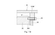
- a spacer 201 may be sandwiched between the fixed flange (12 or 80) and the connecting portion 21.
- annular members having various cross-sectional shapes can be used.
- the spacer 201 may be composed of a plurality of pieces scattered in the circumferential direction.
- the connecting portion 21 is not necessarily formed integrally with the outer casing 22.
- the stop plate 202 may be fixed to the side surface of the outer peripheral casing 22 with a bolt 203, and the connecting portion 21 may be configured by the peripheral portion of the stop plate 202.
- the peripheral portion of the side casing 23 may be projected from the outer peripheral casing 22 to form the connecting portion 21.
- the connecting portion 21 that overlaps the fixing flange (12 or 80) in the axial direction of the cylindrical housing 10 may be in contact with the left side surface (side surface on the support flange 13 side) of the fixing flange, as shown in FIG. .
- the fixing bolt 24 passes through the fixing flange (12 or 80) and is screwed into the screw hole 204 provided in the connecting portion 21.
- the propulsion device main body 20 may not have the connecting portion 21 that overlaps the fixed flange (12 or 80) in the axial direction of the cylindrical housing 10.
- a screw hole 205 is provided on the outer peripheral surface of the outer casing 22, and the cylindrical housing 10 and the fixing flange are fixed to the screw hole 205 so as to penetrate in the radial direction of the cylindrical housing 10.
- the bolt 24 may be screwed. However, in this case, it is necessary to remove the fixing bolt 24 from the hull.
- FIGS. 1 to 19 if the fixing bolt 24 is configured to penetrate the fixing flange (12 or 80) or the connecting portion 21 in the axial direction of the cylindrical housing 10, only the outboard work is required.
- the propulsion unit main body 20 can be removed and attached.
- the thrust generating device according to the present invention can be used as a propulsion device for ships and the like.
- Thrust generator 10 Cylindrical housing 12 Fixed flange 13 Support flange 14 Flow hole (fluid passage) 15 Fixing hole (screw hole) 16 flow hole (liquid flow part) 17 Waterproof tube 20 Propeller body 21 Connecting portion 22 Outer casing 23 Side casing 24 Fixing bolt (fastening member) 25 Stator 26 Armature Coil 27 Power Cable 28 Bolt Insertion Hole 29 Flowing Hole (Liquid Passing Portion) DESCRIPTION OF SYMBOLS 30 Rotor 33 Propeller blades 40, 41 Fairing 45 Large diameter part 46 Small diameter part 50, 51 Water-lubricated bearing 52 Inner peripheral surface 53 Opposing surface 60, 61 Water-lubricated bearing 62 Buffer space 63 Piping 70 Power cable 71 Underwater connector 80 Fixed flange 81 Support flange 82, 83 Flow path forming flange (flow path forming member) 84,85 Flow hole (liquid flow part) 86,87 Opening 90 Cooling channel 91-94 Arrow 100 Hull 101 Cyl 101
Landscapes
- Chemical & Material Sciences (AREA)
- Engineering & Computer Science (AREA)
- Combustion & Propulsion (AREA)
- Mechanical Engineering (AREA)
- Ocean & Marine Engineering (AREA)
- Other Liquid Machine Or Engine Such As Wave Power Use (AREA)
- Structures Of Non-Positive Displacement Pumps (AREA)
- Hydraulic Turbines (AREA)
Abstract
Le dispositif de génération de force de propulsion (1) de l'invention contient : un logement de forme tubulaire (10) ouvert aux deux extrémités dans une direction axiale ; un corps principal d'hélice (20) disposé côté interne du logement de forme tubulaire (10) ; et une paire de carénages (40, 41) installée de manière amovible sur les deux faces latérales du corps principal d'hélice (20). Le corps principal d'hélice (20) contient : un stator (25) de forme circulaire ; un rotor (30) de forme circulaire disposé côté interne du stator (25) ; et des pales d'hélice (33) agencées sur une face périphérique interne du rotor (30). Le logement de forme tubulaire (10) possède un rebord de fixation (12) en saillie vers l'intérieur de la direction radiale. Le corps principal d'hélice (20) est installé de manière amovible sur le rebord de fixation (12) à l'aide d'un élément de serrage (24).
Priority Applications (3)
| Application Number | Priority Date | Filing Date | Title |
|---|---|---|---|
| KR1020157036331A KR101707558B1 (ko) | 2013-06-11 | 2014-06-11 | 추력 발생 장치 |
| CN201480021405.1A CN105209337B (zh) | 2013-06-11 | 2014-06-11 | 推力发生装置 |
| EP14811555.3A EP3009342A4 (fr) | 2013-06-11 | 2014-06-11 | Dispositif de génération de force de propulsion |
Applications Claiming Priority (2)
| Application Number | Priority Date | Filing Date | Title |
|---|---|---|---|
| JP2013122922A JP6204709B2 (ja) | 2013-06-11 | 2013-06-11 | 推力発生装置 |
| JP2013-122922 | 2013-06-11 |
Publications (1)
| Publication Number | Publication Date |
|---|---|
| WO2014199635A1 true WO2014199635A1 (fr) | 2014-12-18 |
Family
ID=52021947
Family Applications (1)
| Application Number | Title | Priority Date | Filing Date |
|---|---|---|---|
| PCT/JP2014/003108 Ceased WO2014199635A1 (fr) | 2013-06-11 | 2014-06-11 | Dispositif de génération de force de propulsion |
Country Status (5)
| Country | Link |
|---|---|
| EP (1) | EP3009342A4 (fr) |
| JP (1) | JP6204709B2 (fr) |
| KR (1) | KR101707558B1 (fr) |
| CN (1) | CN105209337B (fr) |
| WO (1) | WO2014199635A1 (fr) |
Cited By (2)
| Publication number | Priority date | Publication date | Assignee | Title |
|---|---|---|---|---|
| CN114348225A (zh) * | 2021-12-22 | 2022-04-15 | 中国人民解放军海军工程大学 | 一种减振降噪的无轴侧推装置和流道系统 |
| CN115158622A (zh) * | 2022-06-15 | 2022-10-11 | 中国船舶重工集团公司第七一九研究所 | 适应复杂水域的集成电机推进装置 |
Families Citing this family (6)
| Publication number | Priority date | Publication date | Assignee | Title |
|---|---|---|---|---|
| GR1009624B (el) * | 2018-11-02 | 2019-10-23 | Λαλιζας Ανωνυμη Εταιρεια Κατασκευης Και Εμποριας Ναυτιλιακων Σωστικων Και Αθλητικων Ειδων | Προωστηρας θαλασσιου σκαφους αποτελουμενος απο πτυσσομενο στατορα δυο ή περισσοτερων μερων και ροτορα την προπελα που εχει στην περιφερεια της εγκατεστημενους μονιμους μαγνητες |
| KR102444501B1 (ko) * | 2019-11-12 | 2022-09-16 | 한국전기연구원 | 회전 전기기기 및 그를 가지는 추진시스템 |
| CN112339965B (zh) * | 2020-11-26 | 2025-02-11 | 中国船舶重工集团公司第七0四研究所 | 可湿坞拆卸维修的弹性安装式无轴侧推装置 |
| KR102884831B1 (ko) | 2021-03-12 | 2025-11-11 | 바르트실라 네덜란드 비.브이. | 해양 선박을 위한 추진 조립체 |
| US12595036B2 (en) | 2022-04-08 | 2026-04-07 | Taiga Motors Inc. | Rim-driven motor for personal watercraft |
| KR102773304B1 (ko) * | 2022-11-25 | 2025-02-27 | 국방과학연구소 | 해수를 통한 냉각이 가능한 수중 운동체의 추진 장치 |
Citations (5)
| Publication number | Priority date | Publication date | Assignee | Title |
|---|---|---|---|---|
| US20030186601A1 (en) * | 2002-03-29 | 2003-10-02 | Collier Gregory J. | Thruster for submarine vessels |
| JP2009161003A (ja) * | 2007-12-28 | 2009-07-23 | Kawasaki Heavy Ind Ltd | 推力発生装置 |
| WO2009153124A2 (fr) * | 2008-05-27 | 2009-12-23 | Siemens Aktiengesellschaft | Turbomachine pourvue de deux rotors |
| JP2011005927A (ja) | 2009-06-25 | 2011-01-13 | Kawasaki Heavy Ind Ltd | 推力発生装置 |
| JP2011005926A (ja) | 2009-06-25 | 2011-01-13 | Kawasaki Heavy Ind Ltd | 推力発生装置 |
Family Cites Families (7)
| Publication number | Priority date | Publication date | Assignee | Title |
|---|---|---|---|---|
| US1326730A (en) * | 1919-12-30 | Shaetless propeller | ||
| US7220154B2 (en) * | 2003-11-13 | 2007-05-22 | Sword Marine Technology, Inc. | Outboard jet drive marine propulsion system |
| JP4795144B2 (ja) * | 2006-07-05 | 2011-10-19 | 川崎重工業株式会社 | 水力発電装置 |
| CN101546931B (zh) * | 2009-04-28 | 2011-07-27 | 中国船舶重工集团公司第七一二研究所 | 一种集成推进器 |
| NO331651B1 (no) * | 2009-05-20 | 2012-02-13 | Rolls Royce Marine As | Opplagring av propellenhet for et fartøy |
| DE102009040471B4 (de) * | 2009-09-08 | 2016-07-21 | Tutech Innovation Gmbh | Mechanisch angetriebener Schiffpropulsor mit hohem Wirkungsgrad |
| NO335623B1 (no) * | 2009-11-25 | 2015-01-12 | Rolls Royce Marine As | Skyvekraftenhet og fremgangsmåte for installasjon av en skyvekraftenhet |
-
2013
- 2013-06-11 JP JP2013122922A patent/JP6204709B2/ja active Active
-
2014
- 2014-06-11 WO PCT/JP2014/003108 patent/WO2014199635A1/fr not_active Ceased
- 2014-06-11 EP EP14811555.3A patent/EP3009342A4/fr not_active Withdrawn
- 2014-06-11 KR KR1020157036331A patent/KR101707558B1/ko active Active
- 2014-06-11 CN CN201480021405.1A patent/CN105209337B/zh active Active
Patent Citations (5)
| Publication number | Priority date | Publication date | Assignee | Title |
|---|---|---|---|---|
| US20030186601A1 (en) * | 2002-03-29 | 2003-10-02 | Collier Gregory J. | Thruster for submarine vessels |
| JP2009161003A (ja) * | 2007-12-28 | 2009-07-23 | Kawasaki Heavy Ind Ltd | 推力発生装置 |
| WO2009153124A2 (fr) * | 2008-05-27 | 2009-12-23 | Siemens Aktiengesellschaft | Turbomachine pourvue de deux rotors |
| JP2011005927A (ja) | 2009-06-25 | 2011-01-13 | Kawasaki Heavy Ind Ltd | 推力発生装置 |
| JP2011005926A (ja) | 2009-06-25 | 2011-01-13 | Kawasaki Heavy Ind Ltd | 推力発生装置 |
Non-Patent Citations (1)
| Title |
|---|
| See also references of EP3009342A4 * |
Cited By (3)
| Publication number | Priority date | Publication date | Assignee | Title |
|---|---|---|---|---|
| CN114348225A (zh) * | 2021-12-22 | 2022-04-15 | 中国人民解放军海军工程大学 | 一种减振降噪的无轴侧推装置和流道系统 |
| CN115158622A (zh) * | 2022-06-15 | 2022-10-11 | 中国船舶重工集团公司第七一九研究所 | 适应复杂水域的集成电机推进装置 |
| CN115158622B (zh) * | 2022-06-15 | 2023-05-23 | 中国船舶重工集团公司第七一九研究所 | 适应复杂水域的集成电机推进装置 |
Also Published As
| Publication number | Publication date |
|---|---|
| CN105209337B (zh) | 2018-01-12 |
| JP2014240224A (ja) | 2014-12-25 |
| EP3009342A1 (fr) | 2016-04-20 |
| CN105209337A (zh) | 2015-12-30 |
| KR101707558B1 (ko) | 2017-02-16 |
| KR20160018580A (ko) | 2016-02-17 |
| JP6204709B2 (ja) | 2017-09-27 |
| EP3009342A4 (fr) | 2017-04-19 |
Similar Documents
| Publication | Publication Date | Title |
|---|---|---|
| JP6204709B2 (ja) | 推力発生装置 | |
| JP5432606B2 (ja) | 推力発生装置 | |
| JP5281500B2 (ja) | 推力発生装置 | |
| JP5100370B2 (ja) | 推力発生装置 | |
| KR101689228B1 (ko) | 추진장치 | |
| CN104718131B (zh) | 用于船舶的推进系统 | |
| US9017119B2 (en) | Ship propulsion device and ship having the same | |
| KR101205949B1 (ko) | 선박용 추진장치 및 이를 포함하는 선박 | |
| JP2016176350A (ja) | 圧縮機システム | |
| CN114348225B (zh) | 一种减振降噪的无轴侧推装置和流道系统 | |
| KR101444292B1 (ko) | 선박의 클러치 모듈 | |
| KR101205939B1 (ko) | 선박용 추진장치 및 이를 포함하는 선박 | |
| KR101447862B1 (ko) | 선박용 추진기 연결 구조체 및 이를 구비한 선박 | |
| CN105799898A (zh) | 一种大功率万向拖船 | |
| ITLT20140007U1 (it) | Eco drive sistem (eds) la eco drive sistem e' una trasmissione in linea d'asse per imbarcazioni plananti studiata per migliorare l'efficienza , la sicurezza, e il confort di bordo | |
| KR20120137689A (ko) | 선박용 추진장치 및 이를 갖춘 선박 |
Legal Events
| Date | Code | Title | Description |
|---|---|---|---|
| 121 | Ep: the epo has been informed by wipo that ep was designated in this application |
Ref document number: 14811555 Country of ref document: EP Kind code of ref document: A1 |
|
| WWE | Wipo information: entry into national phase |
Ref document number: 2014811555 Country of ref document: EP |
|
| NENP | Non-entry into the national phase |
Ref country code: DE |
|
| ENP | Entry into the national phase |
Ref document number: 20157036331 Country of ref document: KR Kind code of ref document: A |