WO2014199758A1 - Dispositif de mesure de fréquence à décalage doppler et dispositif de mesure de courants de marée équipé de celui-ci - Google Patents
Dispositif de mesure de fréquence à décalage doppler et dispositif de mesure de courants de marée équipé de celui-ci Download PDFInfo
- Publication number
- WO2014199758A1 WO2014199758A1 PCT/JP2014/062663 JP2014062663W WO2014199758A1 WO 2014199758 A1 WO2014199758 A1 WO 2014199758A1 JP 2014062663 W JP2014062663 W JP 2014062663W WO 2014199758 A1 WO2014199758 A1 WO 2014199758A1
- Authority
- WO
- WIPO (PCT)
- Prior art keywords
- doppler shift
- shift frequency
- echo signal
- frequency
- signal component
- Prior art date
- Legal status (The legal status is an assumption and is not a legal conclusion. Google has not performed a legal analysis and makes no representation as to the accuracy of the status listed.)
- Ceased
Links
Images




Classifications
-
- G—PHYSICS
- G01—MEASURING; TESTING
- G01S—RADIO DIRECTION-FINDING; RADIO NAVIGATION; DETERMINING DISTANCE OR VELOCITY BY USE OF RADIO WAVES; LOCATING OR PRESENCE-DETECTING BY USE OF THE REFLECTION OR RERADIATION OF RADIO WAVES; ANALOGOUS ARRANGEMENTS USING OTHER WAVES
- G01S15/00—Systems using the reflection or reradiation of acoustic waves, e.g. sonar systems
- G01S15/02—Systems using the reflection or reradiation of acoustic waves, e.g. sonar systems using reflection of acoustic waves
- G01S15/50—Systems of measurement, based on relative movement of the target
- G01S15/58—Velocity or trajectory determination systems; Sense-of-movement determination systems
- G01S15/60—Velocity or trajectory determination systems; Sense-of-movement determination systems wherein the transmitter and receiver are mounted on the moving object, e.g. for determining ground speed, drift angle, ground track
-
- G—PHYSICS
- G01—MEASURING; TESTING
- G01P—MEASURING LINEAR OR ANGULAR SPEED, ACCELERATION, DECELERATION, OR SHOCK; INDICATING PRESENCE, ABSENCE, OR DIRECTION, OF MOVEMENT
- G01P5/00—Measuring speed of fluids, e.g. of air stream; Measuring speed of bodies relative to fluids, e.g. of ship, of aircraft
- G01P5/24—Measuring speed of fluids, e.g. of air stream; Measuring speed of bodies relative to fluids, e.g. of ship, of aircraft by measuring the direct influence of the streaming fluid on the properties of a detecting acoustical wave
- G01P5/241—Measuring speed of fluids, e.g. of air stream; Measuring speed of bodies relative to fluids, e.g. of ship, of aircraft by measuring the direct influence of the streaming fluid on the properties of a detecting acoustical wave by using reflection of acoustical waves, i.e. Doppler-effect
Definitions
- the present invention relates to, for example, a Doppler shift frequency measuring device that measures a Doppler shift frequency of an ultrasonic wave transmitted in water, and a tide meter provided with the Doppler shift frequency measuring device.
- tidal currents have been measured with a tide meter for the purpose of fishing assistance and marine research.
- the tide meter is attached to the bottom of a ship and includes a transducer that transmits and receives ultrasonic waves at a certain depression angle ⁇ with respect to directions that are 120 degrees apart from each other in the horizontal direction, for example.
- the tidal current meter allows the ship's velocity (relative to the tidal current) from the Doppler shift frequency generated in reflected waves (against water echoes) resulting from countless scatterers (plankton, etc.) in the sea located at the set depth. Calculate water speed).
- the tide meter determines the speed of the ship (ground speed) with respect to the sea floor from the Doppler shift frequency generated in the reflected wave (ground echo) from the sea floor. Furthermore, the tidal current meter determines the tidal current speed from the difference between the ground speed and the speed of water.
- the directivity characteristic of this type of tidal current meter has a main lobe in the direction of the depression angle ⁇ and has a side lobe that opens in an umbrella shape at a certain angle from the main lobe and goes in the vertical direction. .
- the received signal of the transmitter / receiver is obtained by adding the received signal component due to the side lobe to the received signal component due to the main lobe, particularly near the sea floor. There was a problem that the speed could not be measured.
- the angle between the direction of the main lobe and the vertical line is made smaller than the angle between the direction of the side lobe and the vertical line, thereby increasing the intensity of the bottom reflected wave from the side lobe.
- an underwater detection device that is lowered and can extract a reflected wave from the bottom of the main lobe (see Patent Document 1).
- the present invention has been made in view of the circumstances as described above, and provides a Doppler shift frequency measuring apparatus capable of measuring a Doppler shift frequency with higher accuracy than conventional ones and a tide meter including the Doppler shift frequency measurement apparatus. For the purpose.
- the Doppler shift frequency measuring device includes an ultrasonic wave having a main lobe heading in a direction of a predetermined depression angle and a side lobe that opens in an umbrella shape at a predetermined angle from the main lobe and whose main directing direction is a vertical direction.
- a transmitter / receiver for receiving the ultrasonic echo signal, and a signal component in a predetermined cutoff band with the ultrasonic frequency as a center frequency from the echo signal received by the transmitter / receiver.
- a Doppler shift frequency detecting means for detecting a Doppler shift frequency of the echo signal component due to the main lobe included in the echo signal from which the signal component of the cutoff band is removed. .
- the Doppler shift frequency measuring apparatus of the present invention can remove the echo signal component due to the side lobe by the filter means, so that the angle formed by the main lobe pointing direction and the vertical line is different from the conventional one.
- the Doppler shift frequency of the echo signal component due to the main lobe can be detected without reducing it. Therefore, the Doppler shift frequency measuring apparatus of the present invention can measure the Doppler shift frequency with higher accuracy than the conventional one.
- the Doppler shift frequency measuring device of the present invention has a configuration in which the filter means removes an echo signal component generated by reflection of the ultrasonic waves of the side lobes at the bottom of the water.
- the Doppler shift frequency measuring device of the present invention can remove an echo signal component having a relatively strong signal intensity from the bottom of the water due to side lobes.
- the Doppler shift frequency detection means is configured to detect an echo signal component generated by reflecting the ultrasonic waves of the main lobe with a scatterer in water within a predetermined distance range from the water bottom. It has a configuration for detecting the Doppler shift frequency.
- the Doppler shift frequency measurement device of the present invention can detect the Doppler shift frequency of the echo signal component generated in the water near the bottom of the water with higher accuracy than before.
- the ultrasonic wave transmitted by the transducer has a plurality of frequency components different from each other, and the filter means is predetermined with each frequency component as a center frequency.
- the Doppler shift frequency detecting means detects the Doppler shift frequency of the echo signal component by the main lobe included in the echo signal from which the signal component of each stop band is removed. It has a configuration that is to be detected.
- the Doppler shift frequency measuring apparatus of the present invention can detect the Doppler shift frequency of the echo signal component due to the main lobe using the broadband ultrasonic wave having a plurality of frequency components.
- the tide meter of the present invention obtains a Doppler shift frequency measuring device, a ground speed indicating the speed of the ship with respect to the seabed, and a water speed indicating the speed of the ship with respect to a current at a predetermined depth based on the Doppler shift frequency. And a tidal velocity calculation means for calculating a tidal velocity at the predetermined depth from the difference between the ground vessel speed and the water vessel speed.
- the tidal current meter of the present invention includes a Doppler shift frequency measuring device that can measure the Doppler shift frequency with higher accuracy than the conventional one, and therefore calculates the tidal velocity with higher accuracy than the conventional one. can do.
- the present invention can provide a Doppler shift frequency measuring device having an effect that the Doppler shift frequency can be measured with higher accuracy than the conventional one, and a tide meter provided with the Doppler shift frequency measuring device.
- FIG. 4 is a power spectrum of an anti-water echo signal component by a main lobe in a region A shown in FIG. 3 in an embodiment of a tide meter according to the present invention.
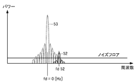
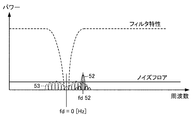
- FIG. 4 is a power spectrum of an anti-water echo signal component by a main lobe and a side lobe in a region B shown in FIG. 3 in one embodiment of the tide meter according to the present invention. It is explanatory drawing of the filter process in one Embodiment of the tide meter which concerns on this invention. It is a flowchart in one Embodiment of the tide meter which concerns on this invention. It is explanatory drawing of the filter process in the other aspect of one Embodiment of the tide meter which concerns on this invention.
- the tide meter 10 in the present embodiment includes a Doppler shift frequency measurement device 20, a tide calculation unit 11, and a display unit 12.
- the tide meter 10 includes a microcomputer (not shown) including a CPU (Central Processing Unit), a ROM (Read Only Memory), a RAM (Random Access Memory), and an input / output circuit to which various interfaces are connected.
- This microcomputer realizes the function of the tide meter 10 by causing a CPU to execute a control program stored in advance in a ROM.
- the tide meter 10 includes an operation unit (not shown), and the user can operate the operation unit to set a depth for measuring a tide, for example.
- the Doppler shift frequency measuring device 20 includes a transmission signal generation unit 21, a transmission amplifier 22, a transmission / reception switching unit 23, a transducer 24, a reception amplifier 25, an analog-digital converter (ADC) 26, a filter 27, and a frequency detection unit 28. Yes.
- ADC analog-digital converter
- the transmission signal generator 21 generates a transmission signal in the ultrasonic band and outputs it to the transmission amplifier 22 (22a to 22c).
- the transmission amplifier 22 (22a to 22c) amplifies the transmission signal generated by the transmission signal generation unit 21 with a predetermined amplification factor and outputs the amplified signal to the transmission / reception switching unit 23.
- the transmission / reception switching unit 23 (23a to 23c) switches between a transmission path from the transmission amplifier 22 to the transmitter / receiver 24 and a reception path from the transmitter / receiver 24 to the reception amplifier 25.
- the transmitter / receiver 24 (24a to 24c) is installed, for example, on the bottom of the ship and transmits ultrasonic waves.
- the transmitter / receiver 24 is arranged so that ultrasonic waves to be transmitted are transmitted into the sea at a certain depression angle so as to be at an angular interval of 120 degrees with respect to the horizontal direction.
- the transmitter / receiver 24 receives an echo signal in which the transmitted ultrasonic wave is reflected by an infinite number of scatterers in the sea and the sea floor, and outputs the echo signal to the reception amplifier 25 via the transmission / reception switching unit 23.
- the reception amplifier 25 (25a to 25c) amplifies the echo signal input from the transmitter / receiver 24 via the transmission / reception switching unit 23 with a predetermined amplification factor and outputs the amplified signal to the ADC 26.
- the ADC 26 (26a to 26c) converts an input analog value signal into a digital value signal and outputs the digital value signal to the filter 27.
- the filter 27 (27a to 27c) removes frequency components in the vicinity of the center frequency from the signal input from the ADC 26, with the frequency of the transmission signal generated by the transmission signal generation unit 21 as the center frequency.
- the filter 27 constitutes filter means according to the present invention.
- the frequency detector 28 (28a to 28c) detects the Doppler shift frequency of the echo signal due to the main lobe at the set depth from the output signal of the filter 27.
- the frequency detector 28 (28a to 28c) constitutes a Doppler shift frequency detector according to the present invention.
- the power flow calculation unit 11 includes a memory (not shown) that stores data of the Doppler shift frequency detected by the frequency detection unit 28. Further, the tidal current calculation unit 11 calculates the water vessel speed at the set depth set by the operation unit (not shown) based on the Doppler shift frequency detected by the frequency detection unit 28, calculates the ground vessel speed, The speed of the tidal current at the set depth is obtained based on the water ship speed and the ground ship speed. This tidal current calculation unit 11 constitutes a tidal current velocity calculating means according to the present invention.
- the display unit 12 is input with the data of the tidal velocity calculated by the tidal current calculating unit 11 and displays the tidal velocity on the screen.
- the transducer 24 transmits ultrasonic waves in three directions.
- the transducers 24a, 24b, and 24c transmit the main lobes 31, 32, and 33, respectively.
- the three main lobes 31 to 33 thus formed have an angular interval of 120 degrees and a predetermined depression angle ⁇ .
- the main lobe 31 is a main lobe heading in the bow direction.
- FIG. 3 is a diagram showing temporal changes in the signal intensity of the echo signal component due to the main lobe and the side lobe.
- the actual echo signal component is a combination of the main lobe and the side lobe, but in order to make the explanation easy to understand, FIG. 3 shows the signal intensity of the echo signal component by the main lobe and the side lobe individually.
- the echo signal 40 includes an echo signal component 41 (solid line) due to the main lobe and an echo signal component 42 (dotted line) due to the side lobe 34.
- the echo signal component 41 due to the main lobe includes an attenuation section 41a in which the anti-water echo signal component generated by reflection from plankton, which is a scatterer in seawater, gradually attenuates over time, and the transmission signal is reflected from the seabed. And a bottom reflection section 41b in which a ground echo signal component is generated.
- the echo signal component 42 by the side lobe 34 similarly includes an attenuation section 42a in which the anti-water echo signal component gradually attenuates over time, and a seabed reflection section 42b in which the ground echo signal component is generated. .
- the attenuation section 41a immediately before the seabed reflection section 41b is a section of seawater in the vicinity of the seabed (hereinafter referred to as “bottom tide”), and is therefore represented as a bottom tide section 41c.
- the bottom tide section 41c is, for example, a section corresponding to a water depth of about 70 m to 100 m if the seabed depth is 100 m.
- the illustrated range that is not affected by the echo by the side lobe 34 is the tidal current measurement possible range.
- FIG. 4 shows an example of the power spectrum of the water echo signal component by the main lobe in the region A where the depth is relatively deep in the tidal current measurable range shown in the figure.
- the water echo signal component 51 in this example has a Doppler shift frequency fd51 having a frequency higher than 0 Hz.
- the frequency detector 28 can easily detect the Doppler shift frequency fd51.
- FIG. 3 an example of the power spectrum of the water echo signal component in the region B is shown in FIG.
- the water echo signal component 52 due to the main lobe has a Doppler shift frequency fd52 having a frequency higher than 0 Hz.
- the frequency detector 28 cannot detect the Doppler shift frequency fd52 in this state.
- the water echo signal component 53 is due to the side lobe 34 whose main directing direction is substantially along the vertical direction, so that the center frequency thereof is a Doppler shift frequency of approximately 0 Hz. Become. That is, the center frequency of the water echo signal component 53 substantially matches the frequency of the ultrasonic signal transmitted by the transducer 24 (the frequency of the ultrasonic wave transmitted into the sea).
- the frequency detector 28 can detect the Doppler shift frequency fd52 when the tidal velocity has a certain speed. That is, the filter 27 can remove the received signal component due to the side lobe from the signal input from the ADC 26.
- the filter 27 is constituted by, for example, a band elimination filter or a band pass filter, and its filter characteristics (center frequency, filter attenuation characteristic, etc.) are set by an operation unit (not shown).
- the transmission signal generation unit 21 generates a transmission signal in the ultrasonic band (step S11) and outputs it to the transmission amplifier 22.
- the transmission amplifier 22 amplifies the transmission signal and outputs it to the wave transmitter / receiver 24 via the transmission / reception switching unit 23.
- the transmitter / receiver 24 transmits ultrasonic waves in the directions of the main lobes 31 to 33 shown in FIG. 2, for example (step S12).
- the transmitter / receiver 24 receives the reflected wave reflected from the object by the transmitted ultrasonic wave, outputs the signal to the receiving amplifier 25 via the transmission / reception switching unit 23, and the receiving amplifier 25 receives the reflected wave signal (step). S13).
- the ADC 26 converts the analog reception signal into a digital reception signal (step S14), and outputs it to the filter 27.
- the filter 27 performs the filtering process described with reference to FIG. 6 (step S15), and the received signal whose signal level of the water echo signal component 53 by the side lobe 34 is equal to or lower than the noise floor level is frequency. Output to the detection unit 28.
- the frequency detection unit 28 detects the Doppler shift frequency of the echo signal component due to the main lobes 31 to 33 at the set depth and the sea floor (step S16), and outputs the detected data to the tidal current calculation unit 11.
- the tidal current calculation unit 11 calculates the speed of the watercraft and the speed of the ground from the Doppler shift frequency according to the above [Equation 1], and calculates the speed of the tidal current at the set depth from the difference between the speed of the ground and the speed of the watercraft. (Step S17).
- the tidal current calculation unit 11 outputs the calculated tidal current velocity data to the display unit 12, and the display unit 12 displays the tidal current velocity data on the screen together with a numerical value indicating the set depth, for example.
- the tide speed is preferably displayed on the display unit 12 as less than 1 knot.
- the filter 27 can remove the echo signal component due to the side lobe, so that the main lobe directing direction and the vertical line are different from the conventional one.
- the Doppler shift frequency of the echo signal component due to the main lobe can be detected without reducing the angle formed. Therefore, the Doppler shift frequency measuring device 20 in the present embodiment can measure the Doppler shift frequency with higher accuracy than the conventional one.
- the tide meter 10 in the present embodiment is configured to include the Doppler shift frequency measurement device 20 that can measure the Doppler shift frequency with higher accuracy than the conventional one, the tide meter 10 has a higher accuracy than the conventional one. Can be calculated.
- the tide meter 10 according to the present embodiment can calculate the bottom tide velocity with high accuracy because the filter 27 removes the echo signal component due to the side lobe.
- the transmission signal generation unit 21 has been described by taking an example of generating a single-frequency transmission signal.
- a description will be given with reference to FIG.
- the transmission signal generation unit 21 generates a wideband transmission signal including signal components of different frequencies f1, f2, and f3.
- This type of transmission signal is generated by, for example, BPSK modulating a carrier wave having a constant frequency with a predetermined code.
- the filter 27 performs comb-type filter processing in which the vicinity of the frequencies at which the Doppler shift frequencies fd1, fd2, and fd3 are each 0 Hz is applied to each side of the signal components of the frequencies f1, f2, and f3.
- the echo signal components 61, 62, and 63 due to the lobe can be attenuated, and the echo signal components 71, 72, and 73 due to the main lobe can be extracted.
- the frequency detector 28 can detect the Doppler shift frequencies fd71, fd72, and fd73 of the echo signal components 71, 72, and 73 due to the main lobe.
- Tidal Current Meter 11 Tidal Current Calculation Unit (Tidal Current Speed Calculation Means) DESCRIPTION OF SYMBOLS 12 Display part 20 Doppler shift frequency measuring device 21 Transmission signal production
Landscapes
- Physics & Mathematics (AREA)
- Engineering & Computer Science (AREA)
- Acoustics & Sound (AREA)
- Radar, Positioning & Navigation (AREA)
- Remote Sensing (AREA)
- General Physics & Mathematics (AREA)
- Computer Networks & Wireless Communication (AREA)
- Multimedia (AREA)
- Aviation & Aerospace Engineering (AREA)
- Measurement Of Velocity Or Position Using Acoustic Or Ultrasonic Waves (AREA)
Abstract
Le problème décrit par la présente invention est de pourvoir à un dispositif de mesure de fréquence à décalage Doppler pouvant mesurer des fréquences à décalage Doppler avec une précision supérieure à celle de dispositifs existants, et de pourvoir à un dispositif de mesure de courants de marée équipé dudit dispositif. La solution selon l'invention porte sur un dispositif (20) de mesure de fréquence à décalage Doppler équipé : d'un transducteur (24) qui émet des ondes ultrasonores dans l'eau et reçoit des signaux d'écho des ondes ultrasonores, le transducteur (24) comportant un lobe principal dirigé dans la direction d'un angle de dépression déterminé, et comportant un lobe latéral dont la direction principale d'orientation consiste en la direction verticale et qui s'ouvre en forme de parapluie à un certain angle désigné à partir du lobe principal ; d'un filtre (27) qui élimine à partir des signaux d'écho reçus au moyen du transducteur (24) les composantes de signaux qui se trouvent dans une bande de coupure déterminée en établissant la fréquence des ondes ultrasonores en tant que fréquence centrale ; et d'une unité de détection (28) de fréquence qui détecte les fréquences à décalage Doppler parmi les composantes de signaux d'écho au niveau du lobe principal qui sont comprises dans les signaux d'écho à partir desquels les composantes de signaux dans la bande de coupure ont été éliminées.
Priority Applications (1)
| Application Number | Priority Date | Filing Date | Title |
|---|---|---|---|
| JP2015522657A JP6403669B2 (ja) | 2013-06-11 | 2014-05-13 | 潮流計 |
Applications Claiming Priority (2)
| Application Number | Priority Date | Filing Date | Title |
|---|---|---|---|
| JP2013122307 | 2013-06-11 | ||
| JP2013-122307 | 2013-06-11 |
Publications (1)
| Publication Number | Publication Date |
|---|---|
| WO2014199758A1 true WO2014199758A1 (fr) | 2014-12-18 |
Family
ID=52022059
Family Applications (1)
| Application Number | Title | Priority Date | Filing Date |
|---|---|---|---|
| PCT/JP2014/062663 Ceased WO2014199758A1 (fr) | 2013-06-11 | 2014-05-13 | Dispositif de mesure de fréquence à décalage doppler et dispositif de mesure de courants de marée équipé de celui-ci |
Country Status (2)
| Country | Link |
|---|---|
| JP (1) | JP6403669B2 (fr) |
| WO (1) | WO2014199758A1 (fr) |
Cited By (8)
| Publication number | Priority date | Publication date | Assignee | Title |
|---|---|---|---|---|
| CN104865404A (zh) * | 2015-06-17 | 2015-08-26 | 王三名 | 一种声学多普勒流速测量仪和流速测量方法 |
| JP2016217958A (ja) * | 2015-05-25 | 2016-12-22 | 古野電気株式会社 | ドップラシフト周波数測定装置、対水速度計、及び潮流計 |
| CN106370886A (zh) * | 2016-08-30 | 2017-02-01 | 厦门博意达科技有限公司 | 微探头超声波多普勒流速仪的控制电路及信号处理方法 |
| EP3401700A4 (fr) * | 2015-09-16 | 2019-05-22 | Furuno Electric Co., Ltd. | Indicateur de vitesse de bateau et procédé d'obtention de vitesse de bateau |
| WO2020037452A1 (fr) * | 2018-08-20 | 2020-02-27 | 深圳市大疆创新科技有限公司 | Procédé et dispositif d'estimation de décalage de point de fréquence, aéronef sans pilote et télécommande |
| CN112415223A (zh) * | 2020-11-19 | 2021-02-26 | 中国科学院大学 | 一种液态金属内部的速度测量方法、装置及存储介质 |
| CN114152774A (zh) * | 2021-12-06 | 2022-03-08 | 中国科学院大学 | 液体流场的流速测量方法、装置、电子设备及存储介质 |
| CN115015576A (zh) * | 2022-06-28 | 2022-09-06 | 中国海洋大学 | 一种时频同步原理的海流及海流计三维运动速度测量方法 |
Citations (3)
| Publication number | Priority date | Publication date | Assignee | Title |
|---|---|---|---|---|
| JPH03242583A (ja) * | 1990-02-20 | 1991-10-29 | Furuno Electric Co Ltd | 水中探知装置 |
| JPH08136642A (ja) * | 1994-11-11 | 1996-05-31 | Nec Corp | 境界面監視ソナー |
| JP2007064768A (ja) * | 2005-08-30 | 2007-03-15 | Furuno Electric Co Ltd | 水中探知装置 |
Family Cites Families (4)
| Publication number | Priority date | Publication date | Assignee | Title |
|---|---|---|---|---|
| JPS61173182A (ja) * | 1985-01-28 | 1986-08-04 | Furuno Electric Co Ltd | 広範囲角水中探知装置に用いる指向性ビ−ム形成方法 |
| JPS63152580U (fr) * | 1987-11-19 | 1988-10-06 | ||
| US5177710A (en) * | 1992-01-31 | 1993-01-05 | Westinghouse Electric Corp. | High speed multibeam sidelock sonar with few elements |
| JP5409452B2 (ja) * | 2010-03-15 | 2014-02-05 | 古野電気株式会社 | 探知装置 |
-
2014
- 2014-05-13 JP JP2015522657A patent/JP6403669B2/ja not_active Expired - Fee Related
- 2014-05-13 WO PCT/JP2014/062663 patent/WO2014199758A1/fr not_active Ceased
Patent Citations (3)
| Publication number | Priority date | Publication date | Assignee | Title |
|---|---|---|---|---|
| JPH03242583A (ja) * | 1990-02-20 | 1991-10-29 | Furuno Electric Co Ltd | 水中探知装置 |
| JPH08136642A (ja) * | 1994-11-11 | 1996-05-31 | Nec Corp | 境界面監視ソナー |
| JP2007064768A (ja) * | 2005-08-30 | 2007-03-15 | Furuno Electric Co Ltd | 水中探知装置 |
Cited By (10)
| Publication number | Priority date | Publication date | Assignee | Title |
|---|---|---|---|---|
| JP2016217958A (ja) * | 2015-05-25 | 2016-12-22 | 古野電気株式会社 | ドップラシフト周波数測定装置、対水速度計、及び潮流計 |
| US10175262B2 (en) | 2015-05-25 | 2019-01-08 | Furuno Electric Co., Ltd. | Doppler shift frequency measuring device, log speed meter and tidal current meter |
| CN104865404A (zh) * | 2015-06-17 | 2015-08-26 | 王三名 | 一种声学多普勒流速测量仪和流速测量方法 |
| EP3401700A4 (fr) * | 2015-09-16 | 2019-05-22 | Furuno Electric Co., Ltd. | Indicateur de vitesse de bateau et procédé d'obtention de vitesse de bateau |
| CN106370886A (zh) * | 2016-08-30 | 2017-02-01 | 厦门博意达科技有限公司 | 微探头超声波多普勒流速仪的控制电路及信号处理方法 |
| WO2020037452A1 (fr) * | 2018-08-20 | 2020-02-27 | 深圳市大疆创新科技有限公司 | Procédé et dispositif d'estimation de décalage de point de fréquence, aéronef sans pilote et télécommande |
| CN112415223A (zh) * | 2020-11-19 | 2021-02-26 | 中国科学院大学 | 一种液态金属内部的速度测量方法、装置及存储介质 |
| CN112415223B (zh) * | 2020-11-19 | 2021-09-24 | 中国科学院大学 | 一种液态金属内部的速度测量方法、装置及存储介质 |
| CN114152774A (zh) * | 2021-12-06 | 2022-03-08 | 中国科学院大学 | 液体流场的流速测量方法、装置、电子设备及存储介质 |
| CN115015576A (zh) * | 2022-06-28 | 2022-09-06 | 中国海洋大学 | 一种时频同步原理的海流及海流计三维运动速度测量方法 |
Also Published As
| Publication number | Publication date |
|---|---|
| JPWO2014199758A1 (ja) | 2017-02-23 |
| JP6403669B2 (ja) | 2018-10-10 |
Similar Documents
| Publication | Publication Date | Title |
|---|---|---|
| JP6403669B2 (ja) | 潮流計 | |
| US8864671B2 (en) | Methods and systems for color flow imaging | |
| JP2007507691A (ja) | ソナー・システムおよびプロセス | |
| RU2488133C1 (ru) | Гидроакустический комплекс для обнаружения движущегося источника звука, измерения азимутального угла на источник и горизонта источника звука в мелком море | |
| KR102374304B1 (ko) | 미식별 수중신호 위치의 추정 방법 및 시스템 | |
| RU2474836C1 (ru) | Гидроакустический комплекс для измерения азимутального угла на источник звука в мелком море | |
| KR20170029899A (ko) | 능동 소나 시스템의 lfm신호 파라미터 추정 장치 및 방법 | |
| JP5235737B2 (ja) | パルスドップラレーダ装置 | |
| JP2012247304A (ja) | 短時間信号のピークパワースペクトルを検出する方法及び装置 | |
| RU2541699C1 (ru) | Гидроакустический способ измерения дистанции с помощью взрывного источника | |
| RU2602759C1 (ru) | Способ автоматического обнаружения и классификации объекта в водной среде | |
| JP6347660B2 (ja) | 魚群探知機、単体魚検出方法、および単体魚検出プログラム | |
| KR100979286B1 (ko) | 수중 거리 및 방위를 측정하는 장치 및 방법 | |
| RU2510608C1 (ru) | Способ измерения толщины льда с подводного носителя | |
| RU2541435C1 (ru) | Способ определения осадки айсберга | |
| RU2650419C1 (ru) | Гидролокационный способ классификации подводных объектов в контролируемой акватории | |
| JP6610224B2 (ja) | バイスタティックアクティブソーナー装置およびその受信器 | |
| RU2655019C1 (ru) | Способ измерения скорости судна доплеровским лагом | |
| JP7638582B2 (ja) | 境界音響反射に基づくターゲット強度自己測定方法及びターゲット強度自己測定システム | |
| RU2476899C1 (ru) | Гидроакустический комплекс для измерения азимутального угла и горизонта источника звука в мелком море | |
| RU85001U1 (ru) | Допплеровский акустический локатор для мониторинга поля ветра и турбулентности в атмосферном пограничном слое | |
| KR101091645B1 (ko) | 도플러 편이 추정장치 및 도플러 편이 추정방법 | |
| JP2014020907A (ja) | 水中探知装置、水中探知方法、及びプログラム | |
| RU2590932C1 (ru) | Гидроакустический способ измерения глубины погружения неподвижного объекта | |
| KR101158792B1 (ko) | 신호의 믹싱기법을 이용한 코히어런트 도플러 유속분포 측정 방법 및 장치 |
Legal Events
| Date | Code | Title | Description |
|---|---|---|---|
| 121 | Ep: the epo has been informed by wipo that ep was designated in this application |
Ref document number: 14811272 Country of ref document: EP Kind code of ref document: A1 |
|
| ENP | Entry into the national phase |
Ref document number: 2015522657 Country of ref document: JP Kind code of ref document: A |
|
| NENP | Non-entry into the national phase |
Ref country code: DE |
|
| 122 | Ep: pct application non-entry in european phase |
Ref document number: 14811272 Country of ref document: EP Kind code of ref document: A1 |