WO2014200002A1 - Chapeau coupé dans une feuille unique - Google Patents
Chapeau coupé dans une feuille unique Download PDFInfo
- Publication number
- WO2014200002A1 WO2014200002A1 PCT/JP2014/065392 JP2014065392W WO2014200002A1 WO 2014200002 A1 WO2014200002 A1 WO 2014200002A1 JP 2014065392 W JP2014065392 W JP 2014065392W WO 2014200002 A1 WO2014200002 A1 WO 2014200002A1
- Authority
- WO
- WIPO (PCT)
- Prior art keywords
- piece
- outer peripheral
- peripheral piece
- cut
- pair
- Prior art date
- Legal status (The legal status is an assumption and is not a legal conclusion. Google has not performed a legal analysis and makes no representation as to the accuracy of the status listed.)
- Ceased
Links
Images





















Classifications
-
- A—HUMAN NECESSITIES
- A42—HEADWEAR
- A42B—HATS; HEAD COVERINGS
- A42B1/00—Hats; Caps; Hoods
- A42B1/208—Hats; Caps; Hoods made from a flat sheet
Definitions
- the present invention relates to a hat cut out from a single sheet.
- Patent Document 1 discloses a crown portion that covers the head by providing an outer periphery of a main body made of a single sheet as a collar and providing a separation boundary line in the inner periphery of the collar. There is shown a seat-type cap characterized in that the holding portion that keeps the shape of the crown portion is integrally formed, and the crown portion and the protruding piece can be designed.
- Japanese Utility Model Laid-Open No. 2-125925 discloses that a sheet, a forehead cover, a ceiling cover, left and right temporal covers, A pair of caps that are continuously cut out without being separated from the pair of occipital covering pieces and the pair of left and right locking bands, bent along a predetermined fold line, and formed by locking the pair of left and right locking bands
- a locking piece is provided at a rear end of the pair of left and right occipital covering pieces, the engaging pieces are overlapped with each other to form a curved portion on the occipital covering piece, and the locking piece is attached to the ceiling portion.
- a cap characterized in that it is engaged with a locking hole formed in the cover piece and the ceiling cover piece is supported substantially horizontally by the elasticity of the front curved portion.
- the seat-type cap disclosed in Japanese Patent Application Laid-Open No. 2009-57674 has the following problems.
- the plug-in type is not suitable as an outdoor hat because the top of the wearer is not covered.
- (B) In addition, in the case of using a hook-and-loop fastener or a fastener for assembling, there is a problem that the cost is increased, and disposal or packaging as a product is troublesome.
- the hat disclosed in Japanese Utility Model Laid-Open No. 2-125925 has the following problems.
- the present invention has been made to solve these problems.
- the hat cut out from one sheet of the present invention It consists of a single sheet that is almost oval.
- An outer peripheral piece provided with a cut in a predetermined width leaving one end in the length direction;
- a U-shaped piece having a predetermined width left inside the outer peripheral piece and having a pair of left and right engaging pieces in the vicinity of the tip;
- a pair of left and right strips formed by cutting a U-shaped portion between the U-shaped piece and the outer peripheral piece in the middle;
- An insertion port for inserting the engaging piece into each of the base portion of the outer peripheral piece, both sides of the cut formed in the outer peripheral piece, and the distal end portion of the strip piece is formed, The first-stage engagement piece of the U-shaped
- the reversing part formed by folding the outer peripheral piece at the cut position is further folded inward with a predetermined width.
- the collar piece is provided with a concave groove corresponding to a pair of left and right engaging pieces formed in two steps near the tip of the U-shaped piece, It is also characterized in that a concave groove is attached to an appropriate position of the assembled hat body.
- the hat cut out from one sheet of the present invention It consists of a single sheet that is almost oval.
- An outer peripheral piece provided by forming a cut in a predetermined width leaving one end in the length direction of the sheet, A U-shaped piece having a predetermined width left inside the outer peripheral piece and having a pair of left and right engaging pieces in the vicinity of the tip; A pair of left and right strips formed by cutting a U-shaped portion between the U-shaped piece and the outer peripheral piece at an intermediate cutting portion; A hook piece cut off at the cutting portion at the end of the pair of left and right strip pieces; Forming a notch with one end open toward the outer periphery at an intermediate position of the outer peripheral piece, and forming a pair of engaging pieces at a predetermined interval along the outer periphery of the base of the outer peripheral piece; Inserting holes of the engaging pieces are formed at both sides of the cut formed in the outer peripheral piece, the tip of the strip piece, and the end position of the outer peripheral piece, The first-stage engagement piece of the U-shaped
- the present invention is a simple hat made of a single sheet.
- a U-shaped piece and a pair of left and right strips are formed, and a first-stage engaging piece provided on the U-shaped piece is formed on the strip.
- the engaging piece formed on the inner periphery of the end position of the outer peripheral piece is inserted into the insertion port formed in the base of the outer peripheral piece, and the reversing portion is used by the user.
- the head is surrounded by a head, and if necessary, the collar piece is attached to an appropriate position of the assembled hat body.
- the hat cut out from one sheet of the present invention has the following effects. a) A U-shaped piece and a pair of left and right strip pieces, and a sufficient gap between the strip piece and the outer peripheral piece so that air permeability is good and the top of the wearer is reliably covered It is suitable as an outdoor hat. b) Further, since no hook-and-loop fasteners or fasteners are used for assembly, the cost is not increased, and disposal or packaging as a product is extremely easy. c) Since the whole is within the elliptical outline, the area of one sheet to be used is small, and the cost can be reduced.
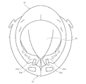
- FIG. 5 From the back side. It is the perspective view which looked at the state which turned up both sides of the perimeter piece from the back side.
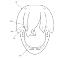
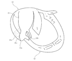
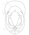
- FIG. 1 It is a perspective view which shows the step which further folds an outer peripheral piece from the middle of the width direction. It is a bottom view in the state where the hat body was completed. It is the perspective view which looked down at the completion state from diagonally upward. It is a perspective view of the state which is going to attach a collar piece to a hat main body.
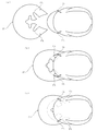
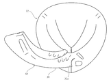
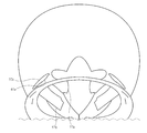
- the attachment process of a scissors is shown, (a) is a plan view showing a state before assembly, (b) is in the middle of assembly, and (c) is an assembled state. It is the perspective view which looked down from the front after completion
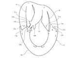
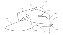
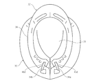
- a hat cut out from one sheet of the present embodiment is configured as follows. That is, the cap 11 of the present embodiment is composed of a substantially elliptical sheet 11a. As the material of the sheet 11a, it is desirable to use a material having a thickness of about 1 to 3 mm. Examples of the material include cloth, cardboard, soft plastic sheet such as EVA (ethylene vinyl acetate) sheet, and heat insulation. It is possible to use not only a plastic foam sheet or a composite sheet thereof, but also a rigid plastic sheet, an FRP sheet made of a carbon material or the like, or a composite sheet thereof.
- EVA ethylene vinyl acetate
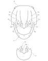
- the cap 11 is provided with an outer peripheral piece 12 formed by forming a cut with a predetermined width while leaving one end in the length direction of the sheet 11a, and a cut with a predetermined width left inside the outer peripheral piece 12. And a U-shaped piece 13 provided with a pair of left and right engaging pieces 14a, 14b and engaging pieces 15a, 15b in the vicinity of the tip, and a U-shape between the U-shaped piece 13 and the outer peripheral piece 12 A pair of left and right strips 16 and 16 formed by cutting a portion at an intermediate cutting part 16a, and a flange piece 17 cut off at the cutting part 16a at the end of the pair of left and right strips 16 and 16 are formed. Has been.
- a notch 12a having one end opened toward the outer periphery is formed at an intermediate position of the outer peripheral piece 12, and the outer peripheral piece 12 is folded back and inverted at the position of the notch 12a.
- Reference numeral 18 denotes an inversion portion.
- a pair of left and right engaging pieces 12b and 12c are formed on the inner periphery of the end portion of the reversing portion 18 of the outer peripheral piece 12.
- the outer peripheral piece 12 is further formed with a folded portion 18b that is folded back in the width direction and inward with a predetermined width at the inversion portion 18.
- the engagement pieces 12b and 12c and the engagement pieces 14a and 14b are respectively formed on the base portion of the outer peripheral piece 12, the both sides of the cut 12a formed in the outer peripheral piece 12, and the tip portions of the strip pieces 16 and 16, respectively.
- insertion ports 21a, 21b, 21c, and 21d into which the engagement pieces 15a and 15b are inserted are formed.
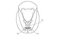
- 22a and 22b are string-through holes provided on the side of the cut 12a on both sides of the folded portion of the reversing portion 18, respectively.
- Reference numeral 23 denotes a blindfold provided at the tip of the U-shaped piece 13.
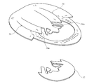
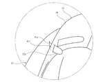
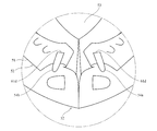
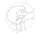
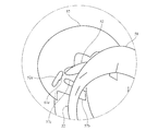
- the hat can be assembled from the single sheet 11a by the following steps. 1) First, as shown in FIG. 2, the collar piece 17 is cut off at the cutting portion 16a at the ends of the pair of left and right strip pieces 16,16. 2) Next, as shown in FIG. 3, the first-stage engaging pieces 14a, 14b of the U-shaped piece 13 are connected to the outer peripheral piece 12 via the insertion port 21a at the tip end portion of the strip pieces 16, 16. It inserts in the insertion port 21b provided inside the notch 12a formed in this. As shown in FIGS. 4 and 5, the second-stage engagement pieces 15 a and 15 b of the U-shaped piece 13 are inserted into an insertion port 21 c provided outside a notch 12 a formed in the outer peripheral piece 12.
- the reversing portion 18 of the outer peripheral piece 12 is folded back at the position of the notch 12a. Thereafter, as shown in FIG. 7, the engaging pieces 12 b and 12 c provided on the inner periphery of the reversing portion 18 of the outer peripheral piece 12 are inserted into the insertion port 21 d provided on the base portion of the outer peripheral piece 12. 4) Further, as shown in FIG. 8, the outer peripheral piece 12 is further folded inward in the width direction and inward at a predetermined width at the reversing portion 18, and the width of the outer peripheral piece 12 is reduced by fitting the insertion port 21e into the engaging piece 18a and stopping.
- the folded portion 18b can be attached to the user's head so as to sandwich the user's temporal region.
- a stapler, a clip, an adhesive, a double-sided adhesive tape, or the like may be used as the locking means for the folded portion 18b.
- each part can be fixed by bonding or sewing, or unnecessary parts can be cut off.
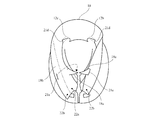
- FIG. 9 shows the completed state.
- the elastic band 22c is bound to the string through holes 22a and 22b, and the elastic piece 12 absorbs the size and adjusts the length to adjust the length of the outer peripheral piece 12. The size of can be changed.
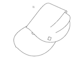
- FIG. 10 is a bird's-eye view of the completed state. 5) As shown in FIG.
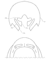
- the flange piece 17 corresponds to a pair of left and right engaging pieces 14a and 14b and engaging pieces 15a and 15b formed in two steps near the tip of the U-shaped piece 13.
- a pair of concave grooves 17a and 17b and fan-shaped pieces 17c and cuts 17d therebetween are provided, and the concave grooves 17a and 17b, the fan-shaped pieces 17c and the cuts 17d are attached to appropriate positions of the hat main body after assembly. Or plug in.
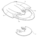
- the flange piece 17 can be used as a flange by being inserted between the upper portion of the outer peripheral piece 12 after being turned back and the inverted portion 18 after being turned back. That is, as shown in FIG. 12A, the opening end of the flange piece 17 is faced toward the end portion of the completed hat body. And it inserts between the upper part of the outer periphery piece 12 of the said hat main body, and the inversion part 18 after folding, and as shown in FIG.12 (b), the concave groove 17a of the said hook piece 17 is the upper part of the said outer periphery piece 12. Are inserted into the engaging pieces 12b and 12c connecting the inverted portion 18 after the turn-back.
- FIG. 12C shows a state in which the hook piece 17 has been attached to the hat body. 13 is a perspective view as seen from the front after completion of assembly, and FIG. 14 is a side view thereof.
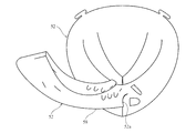
- the collar piece 17 is inserted between the U-shaped piece 13 and the strip pieces 16 and 16 for use as a decoration, or between the base portion of the outer peripheral piece 12 and the tip of the reversing portion 18 located therebelow. It can also be used as a cover for the back of the head. At this time, if the concave grooves 17a and 17b are mounted so as to be engaged with the outer peripheral piece 12, the U-shaped piece 13, and the strip pieces 16 and 16 at the insertion position, the collar piece 17 is securely attached to the hat body without falling off. Can be attached.
- the present invention has the following effects. a) The U-shaped piece 13 and the pair of left and right strips 16 and 16 and the strips 16 and 16 and the outer peripheral piece 12 can be provided with a sufficient gap, have good ventilation, and are worn by the wearer's head. Since the top part is reliably covered, it is suitable as an outdoor hat. b) Further, since no hook-and-loop fasteners or fasteners are used for assembly, the cost is not increased, and disposal or packaging as a product is extremely easy. c) Since the entirety falls within the oval outline, the area of the single sheet 11a to be used is small, and the cost can be reduced.
- the U-shaped piece 13 and the pair of left and right strip pieces 16, 16 have a sufficient gap between the strip pieces 16, 16 and the outer peripheral piece 12, and the air permeability is good. Since the reversing portion 18 surrounds the user's head, the temporal region also has air permeability, and there is no risk of getting steamed even when worn for a long time. e) Since the whole is within the oval outline, it is possible to easily print various designs.
- a hat cut out from one sheet of the present embodiment is configured as follows. That is, the cap 31 of this embodiment is composed of a substantially elliptical sheet 31a. The material of the sheet 31a may be the same as that in the first embodiment.
- the cap 31 is provided with an outer peripheral piece 32 formed by forming a cut with a predetermined width while leaving one end of the sheet 31a in the length direction, and a cut with a predetermined width left inside the outer peripheral piece 32.
- a U-shaped piece 33 provided with a pair of left and right engaging pieces 34a, 34b and engaging pieces 35a, 35b in the vicinity of the tip, and a U-shape between the U-shaped piece 33 and the outer peripheral piece 32.
- a pair of left and right strips 36, 36 formed by cutting a portion at an intermediate cutting part 36a, and a collar piece 37 cut off at the cutting part 36a at the end of the pair of left and right strips 36, 36 are formed. Has been.
- a cut 32a having one end opened toward the outer periphery is formed at an intermediate position of the outer peripheral piece 32, and the outer peripheral piece 32 is folded and inverted at the position of the cut 32a.
- Reference numeral 38 denotes the inversion portion.
- a pair of left and right engaging pieces 32b and 32c are formed in the vicinity of the inner periphery of the end portion of the reversing portion 38 of the outer peripheral piece 32. Further, the front end portions of the strips 36, 36, both sides of the cuts 32a formed in the outer peripheral piece 32 and the inverted positions of the outer peripheral pieces, and the engaging pieces 32b, 32c and the engagement portions at the base of the outer peripheral piece 32, respectively.
- Insertion ports 41a, 41b, 41c, 41d, 41e, 41f, 41g into which the combined pieces 34a, 34b or the engaging pieces 35a, 35b are inserted are formed.
- reference numerals 42a, 42b and 42c denote rubber band engaging pieces provided at predetermined intervals on the cut 32a side of the reversing portion 38.
- Reference numeral 43 denotes a blindfold provided at the tip of the U-shaped piece 13.
- the hat can be assembled from the single sheet 31a by the following steps. 1) First, as shown in FIGS. 16 and 17, the collar piece 37 is cut off at the cutting portion 36 a at the end of the pair of left and right strip pieces 36, 36. 2) Next, as shown in FIG. 18, the first-stage engaging pieces 34a, 34b of the U-shaped piece 33 are connected to the front end portions of the strip pieces 36, 36 through the insertion port 41a in FIG. As shown, it inserts into the insertion port 41b provided inside the cut 32a formed in the outer peripheral piece 32. Further, as shown in FIGS. 20 and 21, the second-stage engagement pieces 35 a and 35 b of the U-shaped piece 33 are inserted into an insertion port 41 c provided outside a notch 32 a formed in the outer peripheral piece 32.
- the insertion holes are arranged near the engagement pieces 32b and 32c provided at the tips of the engagement pieces 32b and 32c in the vicinity of the inner periphery of the reversing portion 38 of the outer periphery piece 32.
- the flange piece 37 corresponds to a pair of left and right engaging pieces 34a, 34b and engaging pieces 35a, 35b formed in two steps near the tip of the U-shaped piece 33.
- a pair of concave grooves 37a and 37b and a fan-shaped piece 37c and an outer piece 37d between them are provided, and the fan-shaped piece 37c and the outer piece 37d are attached or inserted as required at appropriate positions of the hat body after assembly.
- the collar piece 37 can be used as a collar by being inserted between the upper part of the outer peripheral piece 32 after folding and the inverted part 38 after folding. That is, as shown in FIG. 30, the opening end of the flange piece 37 is faced and inserted between the upper part of the outer peripheral piece 32 of the cap body and the reversing portion 38 after the folding, and the fan-shaped piece 37c of the flange piece 37 is inserted. The outer piece 37d is inserted so as to sandwich the engaging pieces 32b and 32c connecting the upper portion of the outer peripheral piece 32 and the reversing portion 38 after folding. Next, as shown in FIG.
- FIG. 32 shows the completed state, in which the rubber band 44 is engaged with any one of the rubber band engaging pieces 42a, 42b, 42c provided at a predetermined interval on the cut 32a side of the reversing portion 38, and its elasticity
- the size of the outer peripheral piece 32 can be changed by absorbing the size or adjusting the length.
- FIG. 33 shows a state where a rubber band is attached.
- a hat cut out from one sheet of the present embodiment is configured as follows. That is, the hat 51 of this embodiment is composed of a substantially elliptical sheet 51a. The material of the sheet 51a may be the same as that in the first embodiment.
- the cap 51 is provided with an outer peripheral piece 52 provided with a cut having a predetermined width while leaving one end in the length direction of the sheet 51a, and a cut with a predetermined width left inside the outer peripheral piece 52. And a U-shaped piece 53 provided with a pair of left and right engaging pieces 54a, 54b and engaging pieces 55a, 55b in the vicinity of the tip, and a U-shape between the U-shaped piece 53 and the outer peripheral piece 52.
- a pair of left and right strip pieces 56, 56 formed by cutting a portion with an intermediate cutting portion 56a, and a collar piece 57 cut off at the cutting portion 56a at the end of the pair of left and right strip pieces 56, 56 are formed. Has been.
- a fan-shaped piece 57a and an outer piece 57b are formed at the opening of the flange piece 57 corresponding to the engaging pieces 54a and 54b or the engaging pieces 55a and 55b.
- 61e is an insertion port formed in the flange piece 57 between the sector piece 57a and the outer piece 57b.
- a notch 52a having one end opened toward the outer periphery is formed at an intermediate position of the outer peripheral piece 52, and the outer peripheral piece 52 is folded back and inverted at the position of the notch 52a.
- Reference numeral 58 denotes the inversion portion.
- a pair of engaging pieces 52b and 52c are formed at predetermined intervals along the outer periphery of the base portion of the outer peripheral piece 52. Then, the engagement pieces 52b, 52c and the engagement pieces 52 are provided at the leading ends of the strip pieces 56, 56, both sides of the notch 52a formed in the outer peripheral piece 52 and the inverted positions of the outer peripheral pieces, and the base of the outer peripheral piece 52, respectively.
- Insertion ports 61a, 61b, 61c, 61d, 61e, 61f, 61g into which the mating pieces 54a, 54b or the engaging pieces 55a, 55b are inserted are formed.
- 62a, 62b, and 62c are rubber band engaging pieces provided at predetermined intervals on the notch 52a side of the reversing portion 58.
- Reference numeral 63 denotes a blindfold provided at the tip of the U-shaped piece 13.
- the hat can be assembled from the single sheet 51a by the following steps. 1) First, as shown in FIGS. 35 and 36, the collar piece 57 is cut off at the cutting portion 56a at the ends of the pair of left and right strip pieces 56, 56. 2) Next, as shown in FIG. 37, the first-stage engaging pieces 54a, 54b of the U-shaped piece 53 are connected to the front end portion of the strip pieces 56, 56 through the insertion port 61a in FIG. As shown, it inserts into the insertion port 61b provided inside the cut 52a formed in the outer peripheral piece 52. Further, as shown in FIGS. 39 and 40, the second-stage engagement pieces 55a and 55b of the U-shaped piece 53 are inserted into an insertion port 61c provided outside a notch 52a formed in the outer peripheral piece 52.
- the collar piece 57 can be used as a collar by being inserted between the upper part of the outer peripheral piece 52 after being folded and the reversing part 58 after being folded. That is, as shown in FIG. 45, the opening ends of the collar pieces 57 face each other, and are inserted between the upper part of the outer peripheral piece 52 of the cap body and the reversing portion 58 after being turned back. 5) Next, as shown in FIGS. 46 and 47, a pair of engaging pieces 52b and 52c formed along the outer periphery of the base portion of the outer peripheral piece 52 are connected to the fan-shaped piece 57a and the outer piece 57b.
- the outer piece 57b is folded from the inner side of the outer peripheral piece 52 and inserted into the other insertion port 61g formed at the tip of the outer peripheral piece 52.
- FIG. 50 shows the completed state, in which the rubber band 64 is engaged with one of the rubber band engaging pieces 62a, 62b, 62c provided at a predetermined interval on the notch 52a side of the reversing portion 58, and its elasticity
- the size of the outer peripheral piece 52 can be changed by absorbing the size or adjusting the length.
- the hat cut out from one sheet of the present invention is configured as described above, the user can sell or provide one sheet as a material for the hat at an outdoor event or sports watching, etc. It is very convenient because it can be assembled easily. Of course, it can be appropriately used not only for outdoor events and sports watching, but also as goods for sales promotion or for purposes such as awning and rain protection in all outdoor activities such as hiking.
Landscapes
- Helmets And Other Head Coverings (AREA)
Abstract
[Problème] L'invention a pour objet de réaliser un chapeau découpé dans une feuille unique. [Solution] La présente invention concerne un chapeau (11) simple obtenu à partir d'une feuille unique (11a), et est configurée de telle façon que, lorsqu'elle est utilisée: un élément (13) en U et une paire d'éléments oblongs (16) gauche et droit sont assemblés en insérant des premiers éléments (14a, 14b) d'interaction réalisés sur l'élément (13) en U dans des ouvertures (21a) d'insertion formées dans les éléments oblongs (16); l'élément (13) en U et un élément périphérique (12) sont également assemblés en insérant des deuxièmes éléments d'interaction (15a, 15b) réalisés sur l'élément en U dans des ouvertures d'insertion (21c) formées dans l'élément périphérique (12) et, après avoir replié l'élément périphérique (12) à des positions spécifiées, en insérant des éléments (12b, 12c) d'interaction formés sur le bord interne de l'élément périphérique (12) dans des ouvertures d'insertion (21d) formées à la base de l'élément périphérique (12) de telle façon que les sections inversées (18) entourent la tête de l'utilisateur; et lorsque nécessaire, un élément (17) de visière est installé dans un position appropriée du corps de chapeau après assemblage.
Applications Claiming Priority (4)
| Application Number | Priority Date | Filing Date | Title |
|---|---|---|---|
| JP2013121553 | 2013-06-10 | ||
| JP2013-121553 | 2013-06-10 | ||
| JP2014119117A JP5636560B1 (ja) | 2013-06-10 | 2014-06-09 | 一枚のシートから切り出した帽子 |
| JP2014-119117 | 2014-06-09 |
Publications (1)
| Publication Number | Publication Date |
|---|---|
| WO2014200002A1 true WO2014200002A1 (fr) | 2014-12-18 |
Family
ID=52022293
Family Applications (1)
| Application Number | Title | Priority Date | Filing Date |
|---|---|---|---|
| PCT/JP2014/065392 Ceased WO2014200002A1 (fr) | 2013-06-10 | 2014-06-10 | Chapeau coupé dans une feuille unique |
Country Status (2)
| Country | Link |
|---|---|
| JP (1) | JP5636560B1 (fr) |
| WO (1) | WO2014200002A1 (fr) |
Citations (4)
| Publication number | Priority date | Publication date | Assignee | Title |
|---|---|---|---|---|
| JPH02125925U (fr) * | 1989-03-29 | 1990-10-17 | ||
| US20020178486A1 (en) * | 2001-06-04 | 2002-12-05 | Kovalenko Vladimir Ivanovich | Hat and method for making same |
| JP3143680U (ja) * | 2008-05-21 | 2008-07-31 | 功一 市川 | 帽子用シート基材並びに帽子 |
| JP2009057674A (ja) * | 2007-08-31 | 2009-03-19 | Hiroaki Nagashima | シート式帽子 |
-
2014
- 2014-06-09 JP JP2014119117A patent/JP5636560B1/ja not_active Expired - Fee Related
- 2014-06-10 WO PCT/JP2014/065392 patent/WO2014200002A1/fr not_active Ceased
Patent Citations (4)
| Publication number | Priority date | Publication date | Assignee | Title |
|---|---|---|---|---|
| JPH02125925U (fr) * | 1989-03-29 | 1990-10-17 | ||
| US20020178486A1 (en) * | 2001-06-04 | 2002-12-05 | Kovalenko Vladimir Ivanovich | Hat and method for making same |
| JP2009057674A (ja) * | 2007-08-31 | 2009-03-19 | Hiroaki Nagashima | シート式帽子 |
| JP3143680U (ja) * | 2008-05-21 | 2008-07-31 | 功一 市川 | 帽子用シート基材並びに帽子 |
Also Published As
| Publication number | Publication date |
|---|---|
| JP2015017354A (ja) | 2015-01-29 |
| JP5636560B1 (ja) | 2014-12-10 |
Similar Documents
| Publication | Publication Date | Title |
|---|---|---|
| US1677187A (en) | Sun visor | |
| US10098400B2 (en) | Adjustable, configurable hat | |
| CA1288899C (fr) | Couvre-chef reglable et son recouvrement | |
| US5655225A (en) | Protective headgear attachment for baseball style caps | |
| US12245652B2 (en) | Surgical cap and method | |
| EP2508090B1 (fr) | Mécanisme de réglage de longueur de périphérie inférieure | |
| US20110083251A1 (en) | Hat construction | |
| US6305029B1 (en) | Protective headwear with decorative and utilitarian attachments | |
| JP5636560B1 (ja) | 一枚のシートから切り出した帽子 | |
| US20080256682A1 (en) | Headwear having attached panels | |
| JP3110940U (ja) | 帽子 | |
| JP2001336020A (ja) | インナキャップ付ヘルメット | |
| JP3114123U (ja) | 帽子 | |
| KR200327114Y1 (ko) | 보조 모자챙 | |
| JP3123353U (ja) | 作業用帽子 | |
| JP3187382U (ja) | 日除け付き帽子 | |
| JP3203543U (ja) | 分離型帽子 | |
| KR200454906Y1 (ko) | 보조차양을 구비한 모자 | |
| KR200327891Y1 (ko) | 일회용 차양모자 | |
| JPS63739Y2 (fr) | ||
| KR101216439B1 (ko) | 차양 모자 | |
| KR101626963B1 (ko) | 모자 결합형 타월 | |
| KR200157265Y1 (ko) | 휴대용 절첩식 차양모자 | |
| KR101348257B1 (ko) | 다기능 손수건 | |
| KR200478613Y1 (ko) | 통풍구를 갖는 이중 챙 모자 |
Legal Events
| Date | Code | Title | Description |
|---|---|---|---|
| 121 | Ep: the epo has been informed by wipo that ep was designated in this application |
Ref document number: 14811100 Country of ref document: EP Kind code of ref document: A1 |
|
| NENP | Non-entry into the national phase |
Ref country code: DE |
|
| 32PN | Ep: public notification in the ep bulletin as address of the adressee cannot be established |
Free format text: NOTING OF LOSS OF RIGHTS PURSUANT TO RULE 112(1) EPC (EPO FORM 1205N DATED 11/03/2016) |
|
| 122 | Ep: pct application non-entry in european phase |
Ref document number: 14811100 Country of ref document: EP Kind code of ref document: A1 |