WO2014203298A1 - Procédé de radiocommunication, système de radiocommunication, station radio et terminal radio - Google Patents
Procédé de radiocommunication, système de radiocommunication, station radio et terminal radio Download PDFInfo
- Publication number
- WO2014203298A1 WO2014203298A1 PCT/JP2013/003910 JP2013003910W WO2014203298A1 WO 2014203298 A1 WO2014203298 A1 WO 2014203298A1 JP 2013003910 W JP2013003910 W JP 2013003910W WO 2014203298 A1 WO2014203298 A1 WO 2014203298A1
- Authority
- WO
- WIPO (PCT)
- Prior art keywords
- radio
- wireless
- virtual cell
- connection
- communication
- Prior art date
- Legal status (The legal status is an assumption and is not a legal conclusion. Google has not performed a legal analysis and makes no representation as to the accuracy of the status listed.)
- Ceased
Links
Images






Classifications
-
- H—ELECTRICITY
- H04—ELECTRIC COMMUNICATION TECHNIQUE
- H04W—WIRELESS COMMUNICATION NETWORKS
- H04W48/00—Access restriction; Network selection; Access point selection
- H04W48/20—Selecting an access point
-
- H—ELECTRICITY
- H04—ELECTRIC COMMUNICATION TECHNIQUE
- H04W—WIRELESS COMMUNICATION NETWORKS
- H04W48/00—Access restriction; Network selection; Access point selection
-
- H—ELECTRICITY
- H04—ELECTRIC COMMUNICATION TECHNIQUE
- H04W—WIRELESS COMMUNICATION NETWORKS
- H04W60/00—Affiliation to network, e.g. registration; Terminating affiliation with the network, e.g. de-registration
-
- H—ELECTRICITY
- H04—ELECTRIC COMMUNICATION TECHNIQUE
- H04W—WIRELESS COMMUNICATION NETWORKS
- H04W76/00—Connection management
- H04W76/10—Connection setup
Definitions
- the present invention relates to a wireless communication method, a wireless communication system, a wireless station, and a wireless terminal.
- next-generation wireless communication technologies have been discussed in order to further increase the speed and capacity of wireless communication in wireless communication systems such as mobile phone systems.
- 3GPP 3rd Generation Partnership Project
- LTE Long Term Evolution
- LTE-A LTE-Advanced
- Heterogeneous Network HetNet
- Carrier Aggregation CA
- CA Carrier Aggregation
- the communication mode can be variously changed for each wireless terminal depending on the network configuration and the communication status.
- there may be many communication points capable of CoMP communication and the number and combination of communication points actually used for signal transmission in CoMP communication vary.
- the number and combination of different types of communication networks and the number and combination of connectable radio frequency carriers are expected to vary.
- the communication mode is not switched efficiently, the communication performance may be prevented from improving.
- the disclosed technology has been made in view of the above, and an object thereof is to provide a wireless communication method, a wireless communication system, a wireless station, and a wireless terminal that can efficiently switch communication modes and improve communication performance. .
- the wireless communication method disclosed in the present application transmits a connection request for connecting to a virtual cell in which a plurality of cells are combined into one, from the wireless terminal, At least one of the plurality of wireless stations forming the virtual cell receives the connection request and establishes connection between the wireless terminal and the plurality of wireless stations forming the virtual cell.
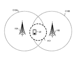
- FIG. 1 is a diagram illustrating a configuration of a wireless communication system according to the first embodiment.
- FIG. 2 is a block diagram showing the configuration of the radio station according to the first embodiment.
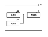
- FIG. 3 is a block diagram showing the configuration of the wireless terminal according to the first embodiment.
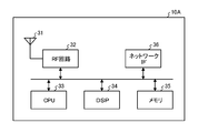
- FIG. 4 is a diagram illustrating a hardware configuration of the radio station according to the first embodiment.
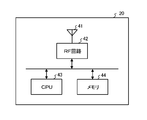
- FIG. 5 is a diagram illustrating a hardware configuration of the wireless terminal according to the first embodiment.
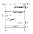
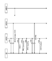
- FIG. 6 is a sequence diagram for explaining the operation of the wireless communication system according to the first embodiment.
- FIG. 7 is a diagram for explaining an operation example of the wireless communication system according to the first embodiment.
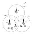
- FIG. 8 is a diagram illustrating a configuration of a wireless communication system according to the second embodiment.
- FIG. 1 is a diagram illustrating a configuration of a wireless communication system according to the first embodiment.
- FIG. 2 is a block diagram showing the configuration of the radio station according to the first embodiment.
- FIG. 3 is a block
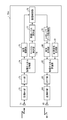
- FIG. 9 is a block diagram showing a configuration of a radio station according to the second embodiment.
- FIG. 10 is a block diagram illustrating a configuration of a wireless terminal according to the second embodiment.
- FIG. 11 is a diagram illustrating an operation related to the operation of the wireless communication system according to the second embodiment.
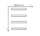
- FIG. 12 is a diagram illustrating an example of a RACH resource related to the description of FIG.
- FIG. 13 is a sequence diagram for explaining the operation of the radio communication system according to the second embodiment.
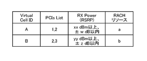
- FIG. 14 is a diagram for explaining an example of the configuration information of the virtual cell of the wireless communication system according to the second embodiment.
- FIG. 15 is a diagram illustrating an example of a RACH resource related to the description of FIG. FIG.
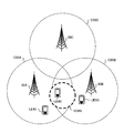
- FIG. 16 is a diagram for explaining an operation example of the wireless communication system according to the second embodiment.
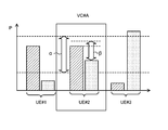
- FIG. 17 is a diagram for explaining determination conditions for establishing a connection in the wireless communication system according to the second embodiment.
- FIG. 18 is a sequence diagram for explaining the operation of the wireless communication system according to the third embodiment.
- FIG. 1 shows a configuration of a wireless communication system 1 according to the first embodiment.
- the radio communication system 1 includes radio stations 10A to 10B and a radio terminal 20.
- Each of the radio stations 10A to 10B has an antenna and corresponds to a communication point.
- the communication point corresponds to, for example, a wireless access point, a base station, a communication unit, an antenna, or a cell formed by these.
- the radio station 10A forms a cell C10A
- the radio station 10B forms a cell C10B.
- the wireless stations 10A to 10B communicate with each other through a wired connection or a wireless connection. Further, the radio stations 10A to 10B can perform CoMP communication with the radio terminal 20. For example, in downlink CoMP communication with the radio terminal 20, one or more communication points selected as a set to be used in downlink CoMP communication among the radio stations 10A to 10B are transmitted to the radio terminal 20 from the same time and frequency. The combined transmission is performed to transmit data using the wireless resources. Further, for example, in uplink CoMP communication with the radio terminal 20, data from the radio terminal 20 is transmitted at one or more communication points selected as a set to be used for uplink CoMP communication among the radio stations 10A to 10B. Each reception is performed, and the combined reception is performed in which the received signals are combined between the communication points.
- the radio stations 10A to 10B are each connected to the network device 3 via a wired connection or a wireless connection, and the network device 3 is connected to the network 2 via a wired connection or a wireless connection.
- the radio stations 10A to 10B are provided so as to be able to transmit and receive data and control information via the network device 3 and the network 2.
- FIG. 2 is a block diagram showing a functional configuration of the radio station 10A.
- the radio station 10A includes a reception unit 11, a transmission unit 12, and a control unit 13. Each of these components is connected so that signals and data can be input and output in one direction or in both directions.
- the functional configuration and hardware configuration of the radio station 10B are the same as the functional configuration and hardware configuration of the radio station 10A. In the following description, it is assumed that the wireless terminal 20 exists in the cell C10A formed by the wireless station 10A and synchronizes with the wireless station 10A when communication is started.
- the receiving unit 11 receives a data signal and a control signal via an antenna.
- the reception unit 11 receives an uplink signal transmitted on an uplink data channel or a control channel.
- An example of the uplink data channel is an individual data channel.
- examples of the uplink control channel include a random access channel and a dedicated control channel.
- a signal to be received for example, a connection request for establishing a connection from the radio terminal 20, a signal indicating a communication level at the radio terminal 20, a reference signal used for channel estimation or demodulation (also referred to as a pilot signal).
- Examples of the connection request include a connection request for connecting to the cell C10A and a connection request for connecting to a virtual cell described later.
- the transmission unit 12 transmits a data signal and a control signal via an antenna.
- the antenna may be common for transmission and reception or may be separate.
- the transmission unit 12 transmits, for example, a downlink signal transmitted on a downlink data channel or control channel.
- Examples of the downlink data channel include a common data channel and a dedicated data channel.
- examples of the downlink control channel include a synchronization channel, a broadcast channel, a common control channel, and an individual control channel.
- a signal to be transmitted for example, a signal for informing system information or control information common to cells, a control signal transmitted to the connected wireless terminal 20 on the dedicated control channel, or a dedicated data channel to the connected wireless terminal 20
- the control signal transmitted above and the data signal transmitted on the dedicated data channel to the connected wireless terminal 20 can be mentioned.
- Examples of the signal to be transmitted include a paging signal for calling the wireless terminal 20 when a call arrives at the wireless terminal 20 and a control signal for controlling the uplink transmission power from the wireless terminal 20. .
- a signal to be transmitted for example, a cell-specific reference signal (also referred to as a common pilot signal), a wireless terminal-specific reference signal (also referred to as an individual pilot signal) used for channel estimation or demodulation
- Configuration information indicating radio resources prepared for transmission of these reference signals is included.
- the signal to be transmitted includes a signal indicating the communication level at the radio stations 10A to 10B and a response signal to the signal for establishing a connection from the radio terminal 20.
- the signal to be transmitted includes configuration information of cell C10A (connection information for connection to cell C10A) and configuration information of peripheral cell C10B of cell C10A (connection information for connection to cell C10B).
- Such configuration information may be broadcast as, for example, system information or control information common to cells.
- the connection information for connecting to the cell C10A includes, for example, identification information for identifying the cell C10A.
- the connection information for connecting to the cell C10B includes, for example, identification information for identifying the cell C10B.
- the signal to be transmitted includes virtual cell configuration information (connection information for connecting to the virtual cell).
- the virtual cell is a cell in which a plurality of cells are combined into one.
- the virtual cell may be referred to as a multi-cell or a group cell, for example.
- a virtual cell may be called a logical cell with respect to the physical cell corresponding to each radio station, for example.
- the virtual cell is formed so as to cover at least a part of each of the plurality of cells.
- the virtual cell configuration information may be broadcasted as system information or common cell control information, for example. Further, for example, the configuration information of the virtual cell may be stored and transmitted in an area prepared in advance in the format of the system information or the control information common to the cells, or may be transmitted in a predetermined control timing or in a predetermined area. The data may be stored and transmitted according to the period.
- the connection information for connecting to the virtual cell includes, for example, identification information for identifying the virtual cell.
- the identification information for identifying the virtual cell includes, for example, a plurality of cell identification information for identifying each of the plurality of cells included in the virtual cell.
- the connection information for connecting to the virtual cell includes, for example, radio resource allocation for transmitting a connection request for connecting to the virtual cell, connection request configuration information for connecting to the virtual cell, virtual cell A determination condition for determining whether or not to connect to may be included.
- the allocation of radio resources indicates, for example, the arrangement of resource elements (also referred to as time frequency resources) used for connection requests.
- the connection request for connecting to the virtual cell is transmitted from the wireless terminal 20 as at least one of random access at the time of initial connection, random access at the time of reconnection, and random access at the time of handover.
- a radio resource for transmitting a connection request for connecting to a virtual cell for example, a radio resource prepared for random access can be used. At this time, for example, a part of radio resources prepared for normal random access is allocated to radio resources for transmitting a connection request for connecting to a virtual cell according to a predetermined control timing or a predetermined period. Also good. Or for example, you may prepare beforehand the radio
- the control unit 13 transmits / receives data and control information to / from the network device 3 and other wireless stations 10B via a wired connection or a wireless connection.
- the control unit 13 inputs received data and control information from the reception unit 11. Further, the control unit 13 outputs data to be transmitted and control information to the transmission unit 12.
- the control unit 13 transmits and receives data and control information via a wired network via a communication interface.
- the control unit 13 performs management such as access management with the wireless terminal 20 and allocation of wireless resources to the wireless terminal 20.
- control unit 13 exchanges information with the peripheral radio station 10B and sets the configuration information of the virtual cell.
- control unit 13 sets possible configuration information of one or a plurality of virtual cells based on the cell arrangement, the wireless communication scheme used in each cell, the radio frequency carrier used in each cell, and the like.
- control unit 13 includes, for example, the number of wireless terminals connected to the wireless station 10A, the communication level between the wireless station 10A and the connected wireless terminal, the number of wireless terminals connected to the other wireless station 10B, Considering at least one of the communication level between the other wireless station 10B and the connected wireless terminal, the communication mode for transmitting data from the wireless station 10A, and the communication mode for transmitting data from the other wireless station 10B
- the configuration information of the virtual cell may be set.
- the communication level between the radio stations 10A to 10B and the radio terminal 20 is measured from, for example, an uplink reference signal or a downlink reference signal.
- the communication level may be reported from the radio terminal 20, and the communication level between the radio station 10A and the radio terminal 20 is measured by the radio station 10A, and the communication level between the radio station 10B and the radio terminal 20 is measured. May be measured by the radio station 10B and notified to the radio station 10A.
- Examples of the communication mode include single antenna communication, MIMO communication, and CoMP communication.
- the MIMO communication includes, for example, MU (Multi-User) -MIMO communication and SU (Single-User) -MIMO communication.
- the CoMP communication includes, for example, DPS (Dynamic Point Selection) -COMP communication, JT (Joint Transmission) -CoMP communication, and JR (Joint reception) -CoMP communication described later.
- DPS is a method of dynamically selecting a communication point to be used for transmission among a plurality of communication points.
- JT is a method for combining (synthesizing) signals transmitted from a plurality of communication points.
- JR is a method of receiving a signal at each of a plurality of communication points and combining (combining) the communication points.
- the virtual cell configuration information may be updated at a predetermined control timing, for example. Further, for example, the configuration information of the virtual cell may be selected at a predetermined control timing from candidates for configuration information stored or set in advance.
- the virtual cell configuration information is commonly used by the radio station 10A and other radio stations around the own station.
- Other wireless stations around the own station include another wireless station 10B capable of CoMP communication.
- the virtual cell configuration information may be set by the radio station 10A or the radio station 10B, for example, and other devices on the network device 3 or the network 2 exchange information with the radio stations 10A to 10B. May be set. Also, the virtual cell configuration information may be notified from one of the radio stations 10A to 10B to the other radio station via wired communication or wireless communication. The apparatus may notify the radio stations 10A-B. Further, instead of notifying the virtual cell configuration information itself, information for selecting predetermined virtual cell configuration information from candidates of configuration information stored or set in advance may be notified. Further, the configuration information of the virtual cell may be stored in, for example, the network device 3 or another device on the network 2, and may be acquired by accessing from the radio stations 10A to 10B at a predetermined control timing. Further, instead of notifying the virtual cell configuration information itself, information for accessing the stored virtual cell configuration information may be notified.
- control part 13 will prepare the connection with the radio
- the control unit 13 establishes a connection by exchanging control information with the wireless terminal. Similarly, other wireless stations forming the virtual cell also exchange control information with the wireless terminal 20 to establish a connection.
- FIG. 3 is a functional block diagram showing the configuration of the wireless terminal 20.
- the wireless terminal 20 includes a reception unit 21, a transmission unit 22, and a control unit 23. Each of these components is connected so that signals and data can be input and output in one direction or in both directions.
- the receiving unit 21 receives data signals and control signals transmitted from the radio stations 10A to 10B via the antenna.
- a signal to be received for example, a signal for reporting system information and control information common to cells, a control signal transmitted from the connection radio station 10A on the dedicated control channel, and a signal transmitted from the connection radio station 10A on the dedicated data channel Control signals.
- the received signal includes, for example, a paging signal for calling the wireless terminal 20, a response signal to a signal for establishing a connection from the wireless terminal 20, a signal indicating the communication level at the wireless stations 10A to 10B, And a control signal for controlling uplink transmission power.
- the received signal includes, for example, a cell-specific reference signal, a reference signal for each wireless terminal used for channel estimation and demodulation, and configuration information indicating a radio resource prepared for transmission of these reference signals.
- the received signal includes, for example, the configuration information of the cell C10A and the configuration information of the neighboring cell C10B transmitted from the radio station 10A. Further, the signal to be transmitted includes, for example, virtual cell configuration information.
- the transmission unit 22 transmits a data signal and a control signal via an antenna.
- the antenna may be common for transmission and reception or may be separate.
- the transmission unit 22 transmits, for example, an uplink signal transmitted on an uplink data channel or a control channel.
- Examples of the signal to be transmitted include a connection request for establishing a connection, a signal indicating a communication level at the wireless terminal 20, and a reference signal used for channel estimation and demodulation.
- Examples of the connection request include a connection request for connecting to the cell C10A and a connection request for connecting to the virtual cell.
- the control unit 23 inputs received data and control information from the reception unit 21. In addition, data to be transmitted and control information are output to the transmission unit 22. In addition, the control unit 23 performs communication control such as management of access to a radio station and control of transmission power of a transmission signal.
- the communication control includes, for example, processing for CoMP communication, processing for carrier aggregation, and processing for handover (Inter-Cell, Inter-Frequency, Inter-Rat, etc.).
- the control unit 23 acquires information indicating a communication state with the radio stations 10A to 10B. Specifically, for example, the control unit 23 detects signals received from the radio stations 10A to 10B, and acquires a communication level. For example, the control unit 23 detects a cell-specific reference signal or a wireless terminal-specific reference signal, and acquires a communication level.
- the communication level includes, for example, reception power and reception quality.
- control unit 23 determines whether to connect to the virtual cell. For example, the control unit 23 determines whether to connect to the virtual cell based on the connection information for connecting to the virtual cell and the information indicating the communication state between the plurality of radio stations forming the virtual cell. To do. Specifically, for example, the control unit 23 uses the identification information for identifying the virtual cell to acquire information indicating the communication state with a plurality of radio stations forming the virtual cell, and sets a predetermined determination condition. To determine whether to connect to the virtual cell. When connecting to the virtual cell, the control unit 23 transmits a connection request for connecting to the virtual cell, receives a response signal, performs a procedure for establishing the connection, and establishes a connection with the virtual cell. .
- FIG. 4 is a diagram illustrating a hardware configuration of the radio station 10A.
- the radio station 10A includes, as hardware components, an RF (Radio Frequency) circuit 32 including an antenna 31, a CPU (Central Processing Unit) 33, a DSP (Digital Signal Processor) 34, and the like. , A memory 35 and a network IF (Interface) 36.
- the CPU is connected via a network IF 36 such as a switch so that various signals and data can be input and output.
- the memory 35 includes at least one of RAM (Random Access Memory) such as SDRAM (Synchronous Dynamic Random Access Memory), ROM (Read Only Memory), and flash memory, and stores programs, control information, and data.
- the transmission unit 12 and the reception unit 11 are realized by the RF circuit 32 or the antenna 31 and the RF circuit 32, for example.
- the control unit 13 is realized by, for example, an integrated circuit such as the CPU 33 or an integrated circuit such as the DSP 34.
- FIG. 5 is a diagram illustrating a hardware configuration of the wireless terminal 20.
- the wireless terminal 20 includes, as hardware components, an RF circuit 42 including an antenna 41, a CPU 43, and a memory 44, for example.
- the wireless terminal 20 may have a display device such as an LCD (Liquid Crystal Display) connected to the CPU 43.
- the memory 44 includes at least one of RAM such as SDRAM, ROM, and flash memory, for example, and stores programs, control information, and data.
- the transmission unit 22 and the reception unit 21 are realized by the RF circuit 42 or the antenna 41 and the RF circuit 42, for example.
- the control unit 23 is realized by an integrated circuit such as the CPU 43, for example.
- FIG. 6 is a sequence diagram for explaining an operation for establishing a connection in the wireless communication system 1
- FIG. 7 is a diagram for explaining an operation example for establishing a connection in the wireless communication system 1.
- the wireless stations 10A to 10B are provided so as to be capable of CoMP communication.
- the radio stations 10A to 10B may use different communication methods.
- the radio stations 10A to 10B may be radio stations capable of carrier aggregation.
- the radio terminal 20 exists in a cell C10A formed by the radio station 10A and a C10B formed in the radio station 10B.
- the communication mode of each communication point is dynamically adjusted at a relatively short cycle so as to increase the allocation by increasing the allocation of radio communication resources to a predetermined radio terminal.
- the communication mode of each communication point can change variously for every radio
- there may be many communication points capable of CoMP communication and the number and combination of communication points actually used for signal transmission in CoMP communication vary.
- the number and combination of different types of communication networks and the number and combination of connectable radio frequency carriers are expected to vary.
- the operation for establishing a connection is performed as follows.
- the radio station 10A sets the virtual cell configuration information and notifies the radio station 10B (S1). Specifically, as shown in FIG. 7, a virtual cell VC1 formed by the radio stations 10A to 10B is set.
- the configuration information of the virtual cell VC1 includes, for example, identification information for identifying the virtual cell VC1, determination conditions for determining whether the wireless terminal 20 requests connection to the virtual cell VC1, and connection to the virtual cell VC1. Including an arrangement of radio resource elements that transmit and receive a connection request.
- the identification information for identifying the virtual cell VC1 includes identification information of each of the radio stations 10A to 10B forming the virtual cell VC1.
- the determination condition is, for example, a condition that the communication performance is assumed to be improved by cooperative cooperation between the radio station 10A and the radio station 10B.
- the reception level from the radio stations 10A to 10B, the reception level from the radio station 10A, and the radio station The relationship with the reception level from 10B is included.
- the radio stations 10A to 10B transmit the configuration information of the virtual cell VC1 (S2).
- the configuration information of the virtual cell VC1 is broadcast from the radio stations 10A to 10B as system information or cell-common control information.
- the wireless terminal 20 determines connection with the virtual cell VC1 (S3). Specifically, the radio terminal 20 measures the reception level of signals from the radio stations 10A to 10B forming the virtual cell VC1 based on the identification information of the virtual cell VC1. Then, whether to make a connection request to the virtual cell VC1 is determined based on the measured reception level and the determination condition set in the configuration information of the virtual cell VC1. In the example of FIG. 7, for example, the reception level from the radio stations 10A to 10B is within a predetermined range, and the difference between the reception level from the radio station 10A and the reception level from the radio station 10B is within the predetermined range. It is determined that a connection request is made to the virtual cell VC1.
- connection request is made to the virtual cell VC1. For example, when the determination condition for requesting connection to the virtual cell VC1 is not satisfied and the determination condition for requesting connection to the cell C10A is satisfied, the connection to the cell C10A is determined.
- the wireless terminal 20 transmits a connection request with the virtual cell VC1 (S4).
- the connection request with the virtual cell VC1 is transmitted using a radio resource element set in the configuration information of the virtual cell VC1.
- a radio resource element set in the configuration information of the virtual cell VC1.
- the wireless station 10A that has received the connection request can recognize that it is a connection request to the virtual cell VC1.
- preparation for connection with the virtual cell VC1 is performed without shifting to establishment of connection to the cell C10A, and shift to communication by cooperative cooperation.
- the radio stations 10A to 10B receive a connection request with the virtual cell VC1, and prepare for connection between the radio terminal 20 and the virtual cell VC1 (S5). Specifically, for example, the wireless station 10A receives a connection request and notifies the wireless station 10B of information for establishing a connection with the wireless terminal 20 from the wireless station 10A.
- connection establishment is executed between the wireless terminal 20 and the wireless stations 10A and 10B (S6).
- connection establishment is executed between the wireless terminal 20 and the wireless stations 10A and 10B (S6).
- the communication performance is improved by cooperative cooperation between the wireless station 10A and the wireless station 10B, for example, whether or not the cooperative cooperation can be performed after the wireless terminal 20 establishes an initial connection with one wireless station 10A.
- communication by cooperative cooperation can be started quickly. That is, switching to cooperative cooperation is performed efficiently.
- the wireless communication system 1 it is possible to efficiently switch the communication mode between the wireless terminal 20 and the wireless stations 10A to 10B and improve the communication performance.
- the radio terminal 20 receives information for connecting to the virtual cell from the other radio stations in synchronization with the other radio stations of the radio communication system 1, and is formed by the radio stations 10A to 10B.
- the connection establishment with the virtual cell to be performed may be executed.
- the wireless communication system 1 has two wireless stations, but the number of wireless stations is arbitrary. Also, a radio station capable of CoMP communication and a radio station not capable of CoMP communication may be mixed. Further, a radio station capable of performing a carrier aggregation operation and a radio station not capable of performing a carrier aggregation operation may be mixed. Further, radio stations using different types of communication methods may be mixed.
- the wireless communication system 1 has one wireless terminal, but the number of wireless terminals is arbitrary. Also, wireless terminals capable of CoMP communication and wireless terminals not capable of CoMP communication may be mixed. In addition, wireless terminals that can perform carrier aggregation operations and wireless terminals that cannot perform carrier aggregation operations may be mixed. Also, wireless terminals that can communicate with different types of communication methods and wireless terminals that are not capable of communicating may be mixed.
- the wireless communication system 1A according to the second embodiment has wireless stations 50A to 50C shown in FIG. 9 described later instead of the wireless stations 10A to 10B, and instead of the wireless terminal 20, Wireless terminals 70A to 70C (also referred to as UE # 1 to UE3) shown in FIG.
- the overall configuration of a wireless communication system 1A according to the second embodiment is the same as that of the wireless communication system 1 shown in FIG.
- each of the wireless stations 50A to 50C is connected to the network device 3 via a wired connection or a wireless connection, and the network device 3 is connected to the network 2 via a wired connection or a wireless connection.
- the radio stations 50A to 50C are provided so as to be able to transmit and receive data and control information via the network device 3 and the network 2.
- each of the radio stations 50A to 50C has an antenna and corresponds to a communication point.
- Radio stations 50A-C form cells C50A-C, respectively.
- the radio stations 50A to 50C communicate with each other via a wired connection or a wireless connection.
- the radio stations 50A to 50C can perform CoMP communication with the radio terminals UE # 1 to UE # 3.
- the radio terminal UE # 1 exists in the cell C50A formed by the radio station 50A
- the radio terminal UE # 2 exists in the cells C50A and B formed by the radio stations 50A and B
- the radio terminal UE # 3. Exists in the cell C50B formed by the radio station 50B.
- FIG. 9 is a block diagram showing a functional configuration of the radio station 50A of the radio communication system 1A according to the second embodiment.
- the functional configuration and hardware configuration of the radio stations 50B to 50C are the same as the functional configuration and hardware configuration of the radio station 50A.
- the radio station 50A includes a reception antenna 51, a reception RF unit 52, an FFT (Fast Fourier Transform) unit 53, a physical channel separation unit 54, a signal demodulation unit 55, and a channel estimation unit 56.
- Unit 63 transmission RF unit 64, and transmission antenna 65.
- the reception antenna 51 receives a radio signal and outputs it to the reception RF unit 52.
- the reception antenna 51 includes, for example, a plurality of antennas (physical antennas).
- the reception antenna 51 may be configured to be shared with the transmission antenna 65 and switched between transmission and reception by a transmission / reception switching unit or the like.
- the reception antenna 51 receives, for example, an uplink signal (data signal or control signal) transmitted on an uplink data channel or control channel. Examples of the physical channel that receives the signal include PRACH (Physical Random Access Channel), PUSCH (Physical Uplink Shared Channel), and PUCCH (Physical Uplink Control Channel).
- PRACH Physical Random Access Channel
- PUSCH Physical Uplink Shared Channel
- PUCCH Physical Uplink Control Channel
- Examples of received signals include RACH (Random Access Channel) signals for establishing connections from the radio terminals UE # 1 to UE3 and signals indicating reception levels at the radio terminals UE # 1 to UE3 (for example, RSRP Report). ) And reference signals for channel estimation and demodulation.
- RACH Random Access Channel
- the reception RF unit 52 performs processing such as A / D (Analog-to-Digital) conversion on the received signal.
- the FFT unit 53 performs FFT processing on the digital signal.
- the physical channel separation unit 54 separates each channel signal from the FFT-processed signal.
- the physical channel separation unit 54 extracts an uplink reference signal included in the uplink signal.
- the uplink reference signal includes, for example, SRS (Sounding Reference Signal) used for channel estimation for each uplink frequency and DM-RS (DeModulation RS) for demodulation of the uplink signal.
- the signal demodulator 55 demodulates the signal of each separated channel based on control information notified or stored in advance or a reference signal for demodulation.
- the channel estimation unit 56 acquires a channel estimation value indicating a channel propagation state based on control information notified or stored in advance or a received reference signal.
- the demodulated signal is decoded based on the channel estimation value.
- the data signal and control signal acquired through the decoding process are output to the communication control unit 58. Further, ACK (ACKnowledgement) / NACK (Negative ACKnowledgement) is output to the communication control unit 58 as a decoding result of the data signal.
- the reception level measurement unit 57 measures the reception level (uplink reception power and uplink reception quality) from the received signal. Examples of the reception level include RSRP, RSRQ, SIR, SINR, and the like.
- the communication control unit 58 transmits / receives data and control information to / from the network device and other wireless stations via a wired connection or a wireless connection. Further, the communication control unit 58 performs communication control such as management of access to the radio terminals UE # 1 to UE # 3 and control of transmission power for transmitting signals.
- the transmission power is controlled by, for example, open loop control that compensates for a propagation loss (path loss) between communication points, adaptive modulation control, and closed loop control using a TPC (Transmission Power Control) command.
- the communication control includes, for example, processing for CoMP communication, processing for carrier aggregation, and processing for handover (Inter-Cell, Inter-Frequency, Inter-Rat, etc.). The details of the communication control unit 58 will be described later.
- the upper layer data processing unit 59 performs reordering processing of the decoded data signal and acquires uplink user data. Further, the upper layer data processing unit 59 processes downlink user data acquired from a network device or another wireless station and control information to be transmitted to generate a transmission packet.
- the signal generator 60 encodes and modulates the transmission packet and outputs it to the physical channel multiplexer 62.
- the signal generation unit 60 generates a control signal transmitted on the dedicated control channel and outputs the control signal to the physical channel multiplexing unit 62.
- the reference signal generator 61 generates a downlink reference signal and outputs it to the physical channel multiplexer 62.
- the downlink reference signal is a radio terminal used for downlink cell-specific CRS (Cell-specific Reference Signal), downlink CSI-RS (Channel State Information Reference Signal), downlink channel estimation and signal demodulation, for example. Includes an individual reference signal (DM-RS).
- the CRS is used for measurement of downlink communication quality and demodulation of downlink signals, and is set in association with cell identification information (cell ID).
- CSI-RS is used for measurement of downlink communication quality, and can be set for each communication point, for example.
- the physical channel multiplexing unit 62 allocates the encoded / modulated transmission packet, control signal, and reference signal to the physical channel radio resource according to the scheduling of the communication control unit 58.
- the IFFT unit 63 performs IFFT processing on the multiplexed signal.
- the transmission RF unit 64 performs D / A conversion, distortion compensation processing, amplification processing, and the like on the signal after IFFT processing and outputs the result to the transmission antenna 65.
- the transmission antenna 65 transmits a radio signal input from the transmission RF unit 64.
- the transmission antenna 65 includes, for example, a plurality of antennas.
- the transmission antenna 65 transmits, for example, a downlink signal (data signal or control signal) transmitted on a downlink data channel or control channel.
- Examples of physical channels that transmit signals include broadcast channels PBCH (Physical road Broadcast Channel), PMCH (Physical Multicast Channel), shared channel PDSCH (Physical Downlink Shared Channel), dedicated control channel PDCCH (Physical Downlink Control Channel), and the like.
- E-PDCCH Enhanced--Physical-Downlink-Control-Channel).
- a signal to be transmitted for example, when a call arrives at the radio terminals UE # 1 to UE # 3, a PCH (Paging Channel) signal for calling the radio terminals UE # 1 to UE3, or a response signal to the RACH signal ( RAR, Random Access Response).
- the signal to be transmitted include a signal indicating the reception level at the radio station 50A, and a control signal (for example, downlink transmission power information, a TPC command, etc.) for controlling the uplink transmission power.
- the signal to be transmitted is, for example, a reference signal for each wireless terminal used for channel estimation or demodulation, a plurality of configuration information indicating a radio resource prepared for transmission of a reference signal for each wireless terminal, or a plurality of configurations
- Each of the information includes a signal that specifies a use mode related to use of the radio resource indicated by the information.
- Examples of the control signal include L1 / L2 signaling transmitted on the dedicated wireless channel to the connected wireless terminal and RRC (Radio Resource Control) signaling transmitted on the shared channel to the connected wireless terminal.
- the control signal includes, for example, system information that is stored in MIB (Master Information Block) or SIB (System Information Block) and transmitted on a broadcast channel or a shared channel designated by the broadcast channel.
- the communication control unit 58 performs management of access to the radio terminals UE # 1 to UE3 and scheduling of allocation of radio resources to the radio terminals UE # 1 to UE3.
- the communication control unit 58 exchanges information with the peripheral radio stations 50B to 50C, for example, and sets the virtual cell configuration information.
- the communication control unit 58 sets configuration information of one or a plurality of virtual cells that can be taken based on, for example, the cell arrangement, the radio communication scheme used in each cell, the radio frequency carrier used in each cell, and the like. .
- the communication control unit 58 also transmits, for example, the number of wireless terminals to which the wireless stations 50A to 50C are connected, the communication level between the wireless stations 50A to 50C and the connected wireless terminals, and data transmitted from the wireless stations 50A to 50C.
- the configuration information of the virtual cell may be set in consideration of at least one of the communication modes to be performed.
- the communication level between the radio stations 50A to 50C and the radio terminals UE # 1 to UE # 3 is measured from, for example, an uplink reference signal or a downlink reference signal.
- the communication level may be reported from the radio terminals UE # 1 to UE # 3, for example.
- the communication level between the radio station 50A and the radio terminals UE # 1 to 3 is measured by the radio station 50A, and the communication level between the radio station 50B and the radio terminals UE # 1 to UE3 is measured. May be measured by the radio station 50B, the communication level between the radio station 50C and the radio terminals UE # 1 to UE # 3 may be measured by the radio station 50C, and notified from the radio stations 50B to 50A to the radio station 50A.
- Examples of the communication mode include single antenna communication, MIMO communication, and CoMP communication.
- the virtual cell configuration information may be updated at a predetermined control timing, for example. Further, for example, the configuration information of the virtual cell may be selected at a predetermined control timing from candidates for configuration information stored or set in advance.
- the virtual cell configuration information is commonly used by the radio station 50A and other radio stations around the own station.
- Other radio stations in the vicinity of the own station include other radio stations 50B to 50C capable of CoMP communication.
- the configuration information of the virtual cell may be set by the radio station 50A or may be set by the radio stations 50B to C, and other devices on the network device 3 or the network 2 may exchange information with the radio stations 50A to 50C. You may set by exchanging. Further, the configuration information of the virtual cell may be notified from one of the radio stations 50A to 50C to another radio station via wired communication or wireless communication. May be notified to the radio stations 50A to 50C. Further, instead of notifying the virtual cell configuration information itself, information for selecting predetermined virtual cell configuration information from candidates of configuration information stored or set in advance may be notified.
- the configuration information of the virtual cell may be stored in, for example, the network device 3 or another device on the network 2 and may be obtained by accessing from the radio stations 50A to 50C at a predetermined control timing. Further, instead of notifying the virtual cell configuration information itself, information for accessing the stored virtual cell configuration information may be notified.
- the communication control part 58 will prepare the connection with radio
- the communication control unit 58 establishes a connection by exchanging control information with the wireless terminal. Similarly, other radio stations forming the virtual cell also exchange control information with the radio terminals UE # 1 to UE # 3 to establish a connection.
- FIG. 10 is a block diagram showing a functional configuration of the wireless terminal 70A of the second embodiment.
- the radio terminal 70A includes a reception antenna 71, a reception RF unit 72, an FFT unit 73, a physical channel separation unit 74, a signal demodulation unit 75, a channel estimation unit 76, and a reception level measurement.
- the functional configuration and hardware configuration of the wireless terminals 70B to 70C are the same as the functional configuration and hardware configuration of the wireless terminal 70A.
- the reception antenna 71 receives a radio signal and outputs it to the reception RF unit 72.
- the reception antenna 71 includes, for example, a plurality of antennas.
- the reception antenna 71 may be configured to be shared with the transmission antenna 85 and switched between transmission and reception by a transmission / reception switching unit or the like.
- the reception antenna 71 receives, for example, an uplink signal (data signal or control signal) transmitted on an uplink data channel or control channel. Examples of the received signal include a PCH signal for calling the wireless terminal 70A when a call arrives at the wireless terminal 70A, and a response signal to the RACH signal from the wireless terminal 70A.
- examples of the received signal include a signal indicating the reception level at the radio stations 50A to 50C, and a control signal for controlling uplink transmission power (for example, downlink transmission power information, TPC command, etc.).
- the received signal includes, for example, a reference signal for each wireless terminal used for channel estimation and demodulation, and configuration information indicating a wireless resource prepared for reference signal transmission.
- the signal to be transmitted includes configuration information of the cell C50A (connection information for connecting to the cell C50A) and configuration information of the peripheral cells C50B to C of the cell C50A (connection information for connecting to the cells C50B to C).
- the connection information for connecting to the cells C50A-C includes, for example, identification information for identifying the cells C50A-C.
- the signal to be transmitted includes virtual cell configuration information (connection information for connecting to the virtual cell).
- the connection information for connecting to the virtual cell includes, for example, identification information for identifying the virtual cell.
- the identification information for identifying the virtual cell includes, for example, a plurality of cell identification information for identifying each of the plurality of cells forming the virtual cell. Specifically, identification information for identifying a virtual cell is indicated by, for example, a combination (list) of PCI (Physical Cell ID) for identifying each of a plurality of cells forming the virtual cell. It is.
- the connection information for connecting to the virtual cell includes, for example, radio resource allocation for transmitting a connection request for connecting to the virtual cell, connection request configuration information for connecting to the virtual cell, virtual cell The determination condition for determining whether to connect to is included.
- control signal examples include L1 / L2 signaling transmitted on the dedicated control channel from the connection radio station 50A and RRC signaling transmitted on the shared channel from the connection radio station 50A.
- the control signal includes, for example, system information stored in MIB or SIB and transmitted on a broadcast channel or a shared channel designated by the broadcast channel.
- the reception RF unit 72 performs processing such as A / D conversion on the received signal.
- the FFT unit 73 performs FFT processing on the digital signal.
- the physical channel separation unit 74 separates each channel signal from the FFT-processed signal. For example, the physical channel separation unit 74 obtains a subcarrier signal from a received OFDM (Orthogonal Frequency Division Multiplexing) signal.
- the signal demodulator 75 demodulates the signal of each separated channel based on control information notified or stored in advance or a reference signal specific to each radio terminal for demodulation.
- the channel estimation unit 76 acquires a channel estimation value indicating a channel propagation state based on control information notified or stored in advance or the received reference signal for each wireless terminal.
- the demodulated signal is decoded based on the channel estimation value.
- the user data and control information acquired through the decryption process are output to the communication control unit 78. Further, ACK / NACK is output to the communication control unit 78 as a decoding result of the data signal.
- the reception level measuring unit 77 measures the reception level (downlink reception power and downlink reception quality) from the received signal.
- reception levels include RSRP, RSRQ, SIR, SINR, and the like.
- the signals used include, for example, cell-specific reference signals.
- the communication control unit 78 performs communication control such as access management with the radio stations 50A to 50C and control of transmission power for transmitting signals.
- the transmission power is controlled by, for example, open loop control that compensates for propagation loss (path loss) between communication points, adaptive modulation control, and closed loop control using a TPC command.
- the communication control includes, for example, processing for CoMP communication, processing for carrier aggregation, and processing for handover (Inter-Cell, Inter-Frequency, Inter-Rat, etc.).
- the upper layer data processing unit 79 performs a reordering process on the decoded data signal and acquires the downlink user data. Further, the upper layer data processing unit 79 processes uplink user data and control information to be transmitted, and generates a transmission packet.
- the signal generation unit 80 encodes and modulates the transmission packet, adjusts the amplitude based on the uplink transmission power information, and outputs it to the physical channel multiplexing unit 82.
- the reference signal generation unit 81 generates an uplink reference signal and outputs it to the physical channel multiplexing unit 82.
- the physical channel multiplexing unit 82 assigns the encoded and modulated transmission packet and reference signal to the physical channel radio resource.
- the IFFT unit 83 performs IFFT processing on the multiplexed signal.
- the transmission RF unit 84 performs D / A conversion, distortion compensation processing, amplification processing, and the like on the signal after IFFT processing, and outputs the result to the transmission antenna 85.
- the transmission antenna 85 transmits a radio signal input from the transmission RF unit 84.
- the transmission antenna 85 includes, for example, a plurality of antennas.
- the transmission antenna 85 transmits, for example, an uplink signal (data signal or control signal) transmitted on an uplink data channel or control channel.
- the transmitted signal includes, for example, a RACH signal for establishing a connection, a signal indicating a reception level at the radio terminal 70A, and a reference signal for channel estimation and demodulation.
- the communication control unit 78 determines whether or not to connect to the virtual cell. For example, the communication control unit 78 determines whether to connect to the virtual cell based on the connection information for connecting to the virtual cell and the information indicating the communication state between the plurality of radio stations forming the virtual cell. decide. Specifically, for example, the communication control unit 78 uses the identification information for identifying the virtual cell to acquire information indicating the communication state with a plurality of radio stations forming the virtual cell, and the predetermined determination condition Is used to determine whether or not to connect to the virtual cell. Then, when connecting to the virtual cell, the communication control unit 78 transmits a connection request for connecting to the virtual cell, receives a response signal, performs a procedure for establishing the connection, and establishes a connection with the virtual cell. To do.
- the hardware configuration of the radio station 50A in the radio communication system according to the second embodiment is the same as the hardware configuration of the radio station 10A of FIG.
- the reception antenna 51, the reception RF unit 52, the transmission RF unit 64, and the transmission antenna 65 of the radio station 50A are realized by, for example, an antenna and an RF circuit.
- the signal generation unit 60, the reference signal generation unit 61, the physical channel multiplexing unit 62, and the IFFT unit 63 are realized by an integrated circuit such as a DSP or an integrated circuit such as a CPU.
- the hardware configuration of the wireless terminal 70A in the wireless communication system according to the second embodiment is the same as the hardware configuration of the wireless terminal 20 of FIG.
- the reception antenna 71, the reception RF unit 72, the transmission RF unit 84, and the transmission antenna 85 of the wireless terminal 70A are realized by, for example, an antenna and an RF circuit.
- An FFT unit 73 An FFT unit 73, a physical channel separation unit 74, a signal demodulation unit 75, a channel estimation unit 76, a reception level measurement unit 77, a communication control unit 78, an upper layer data processing unit 79, and a signal of the radio terminal 70A
- the generation unit 80, the reference signal generation unit 81, the physical channel multiplexing unit 82, and the IFFT unit 83 are realized by an integrated circuit such as a CPU, for example.
- the radio stations 10A to 10C are provided as a communication mode so that CoMP communication is possible.
- the radio stations 10A to 10C may use different communication methods.
- the radio stations 10A to 10C may be radio stations capable of carrier aggregation.
- the radio terminal UE # 2 exists in the cells C50A and B formed by the radio stations 50A and B.
- connection establishment operation between the radio terminal UE and the radio stations eNB # 1 to 3 in the existing radio communication system will be described with reference to FIGS.
- the arrangement of the radio terminal UE and the radio stations eNB1 # 1 to 3 is the same as the arrangement of the radio terminal UE # 2 and the radio stations 50A to 50C.
- the radio stations eNB # 1-2 transmit signals of the broadcast channel BCH and the common control channel Common CCH (S21).
- the signals of the broadcast channel BCH and the common control channel Common ⁇ ⁇ ⁇ CCH are also transmitted from the radio station eNB # 3, but cannot be received by the radio terminal UE and can receive signals from the radio stations eNB # 1-2. is there.
- the reception level of the signal from the radio station eNB # 1 is higher than the reception level of the signal from the radio station eNB # 2.
- the radio terminal UE acquires a radio resource element for transmitting the RACH to the radio station eNB # 1.
- FIG. 12 illustrates RACH resources.
- the horizontal axis represents frequency (f) and the vertical axis represents time (t).
- subjected shows the example of the radio
- the radio terminal UE exchanges signals with the radio station eNB # 1 to establish a connection (RRC Connected) (S23).
- the radio terminal UE first establishes a connection with one radio station.
- the radio terminal UE receives an RRC signal (RRC Signaling) from the radio station eNB # 1 (S24).
- the radio terminal UE receives CSI-RSs from the radio stations eNB # 1-2 using the control information based on the RRC signal (S25).
- the radio terminal UE transmits a response (CSI Feedback) to the CSI-RS.
- the radio terminal UE transmits the reception level measured by the CSI-RS to the radio station eNB # 1 to execute the process of cooperative cooperation, or requests the cooperation cooperation based on the measured reception level. It transmits to radio station eNB # 1 (S26).
- FIG. 13 is a sequence diagram of a connection establishment operation between the radio terminal UE # 2 and the radio stations 50A to 50C in the radio communication system 1A.
- the radio station 50A sets virtual cell configuration information (Virtual Cell Information Set) and notifies the radio stations 50B to 50C (S41).
- the virtual cell configuration information includes, for example, identification information for identifying the virtual cell, determination conditions for determining whether or not the wireless terminal requests connection to the virtual cell, and connection requests for connection to the virtual cell. Including arrangement of radio resource elements to be performed.
- FIG. 14 illustrates the configuration information of the virtual cell. In the example of FIG. 14, virtual cells VC # A-B are set.
- FIG. 15 illustrates a RACH resource.
- the horizontal axis represents frequency (f) and the vertical axis represents time (t).
- the hatched part is set as the RACH resource (a) for VC # A, and the hatched part is set as the RACH resource (b) for VC # B. Is done.
- the radio stations 50A to 50B transmit the configuration information of the virtual cells VC # A and B (S42).
- the virtual cells VC # A and B are broadcast from the radio stations 50A to 50B as BCH or Common CCH, respectively.
- the radio terminal UE # 2 synchronizes with the radio stations 50A to 50B, and acquires the configuration information of the virtual cells VC # A and B from the BCH or Common CCH received from the radio stations 50A to 50B (S43). ).
- the radio terminal UE # 2 receives the synchronization channel SCH transmitted from the radio stations 50A to 50B and synchronizes with the radio stations 50A to 50B.
- the radio terminal UE # 2 determines connection with the virtual cell VC # A. Specifically, the radio terminal UE # 2 receives signals from the radio stations 50A to 50B forming the virtual cell VC # A and measures the reception level. Then, whether to make a connection request to the virtual cell VC # A is determined based on the measured reception level and the determination condition.
- FIG. 16 illustrates the virtual cell VC # A.
- FIG. 17 shows an example of determination conditions for the virtual cell VC # A. In FIG. 17, the vertical axis indicates the reception level (p), and the horizontal direction indicates radio terminals UE # 1, UE # 2, UE # 3 in order from the left.
- the left hatched portion indicates the reception level from the radio station 50A
- the right dotted portion indicates the reception level from the radio station 50B.
- connection to the cell C50A is determined. Is done. Further, for example, when the determination condition for requesting connection to the cell C50B is not satisfied and the determination condition for requesting connection to the cell C50B is not satisfied, as in the case of the radio terminal UE # 3, the connection to the cell C50B is determined. Is done.
- the radio terminal UE # 2 transmits a connection request (Virtual Cell Connection Request) with the virtual cell VC # A (S44).
- the connection request with the virtual cell VC # A is transmitted using the radio resource element a set in the configuration information of the virtual cell VC # A.
- a part of the radio resource elements prepared for establishing a connection to the cells C50A and B is allocated to the virtual cell VC # A.
- the radio station 50A that has received the connection request grasps that it is a connection request to the virtual cell VC # A. can do.
- preparation for connection with the virtual cell VC # A is executed without shifting to the establishment of connection to the cell C50A, and the shift to communication by cooperative cooperation is performed.
- the radio stations 50A to 50B receive the connection request with the virtual cell VC # A and prepare the connection between the radio terminal UE # 2 and the virtual cell VC # A (Virtual Cell Connection Setup) (S45). Specifically, for example, the radio station 50A receives the connection request, and notifies the radio station 50B of information for establishing a connection with the radio terminal UE # 2.
- connection establishment (RRC Connected) is executed between the radio terminal UE # 2 and the radio stations 50A and 50B (S46).
- connection establishment RRC Connected
- the cooperative cooperation is performed after the wireless terminal UE # 2 establishes the initial connection with the single wireless station 50A, for example.
- communication by cooperative cooperation can be quickly started. That is, switching to cooperative cooperation is performed efficiently.
- the radio communication system 1A it is possible to efficiently switch the communication mode between the radio terminals UE # 1 to UE # 3 and the radio stations 50A to 50C and improve the communication performance.
- the wireless communication system 1 may be a heterogeneous network in which wireless stations having different cell ranges are mixed.
- one of the radio stations 10A to 10B forms a PCell (Primary cell), and the other of the radio stations 10A to 10B forms an SCell (Secondary cell).
- the SCell is a cell whose function may be more limited than that of the PCell. SCell corresponds to a relatively large cell (Macro Cell), and Pcell corresponds to a relatively small cell (Small Cell).
- PCell is a serving cell (connected cell) of PCC (PrimaryPrimcomponent carrier)
- SCell is a serving cell (connected cell) of SCC (Secondary component carrier).
- PCC is switched by handover, while SCC is added or deleted as necessary.
- the overall configuration of the wireless communication system according to the third embodiment is the same as that of the wireless communication system 1A shown in FIG.
- each of the wireless stations 50A to 50C is connected to the network device 3 via a wired connection or a wireless connection
- the network device 3 is connected to the network 2 via a wired connection or a wireless connection.
- the radio stations 50A to 50C are provided so as to be able to transmit and receive data and control information via the network device 3 and the network 2.
- each of the radio stations 50A to 50C has an antenna and corresponds to a communication point.
- Radio stations 50A-C form cells C50A-C, respectively.
- the radio stations 50A to 50C communicate with each other via a wired connection or a wireless connection.
- the radio stations 50A to 50C can perform CoMP communication with the radio terminals UE # 1 to UE # 3.
- the radio terminal UE # 1 exists in the cell C50A formed by the radio station 50A
- the radio terminal UE # 2 exists in the cells C50A and B formed by the radio stations 50A and B
- the radio terminal UE # 3. Exists in the cell C50B formed by the radio station 50B.
- the functional configuration and hardware configuration of the radio stations 50A to 50C according to the third embodiment are the same as those of the radio station 50A of FIG. 9 of the second embodiment. Also, the functional configurations and hardware configurations of the radio terminals UE # 1 to UE # 3 according to the third embodiment are the same as those of the radio terminal 70A of FIG. 10 of the second embodiment.
- FIG. 18 is a sequence diagram for explaining an operation of establishing a connection in the wireless communication system according to the third embodiment.
- the connection establishment operation shown in the second embodiment is applied to the handover processing procedure.
- the wireless stations 10A to 10C are provided so as to be capable of CoMP communication.
- the radio stations 10A to 10C may use different communication methods.
- the radio stations 10A to 10C may be radio stations capable of carrier aggregation.
- the radio terminal UE # 2 exists in the cells C50A and B formed by the radio stations 50A and B.
- connection establishment (RRCRRConnected) between the radio terminal UE # 2 and the radio station 50A is executed (S61), and the radio terminal UE # 2 is connected to the radio station 50A. It is in.
- the radio station 50A sets the virtual cell configuration information (Virtual Cell Information Set) with the radio station 50B (S62). For example, the radio station 50A sets the virtual cell configuration information and notifies the radio stations 50B to 50C.
- the configuration information of the virtual cell includes, for example, identification information for identifying the virtual cell, determination conditions for determining whether or not the radio terminals UE # 1 to UE # 3 request connection to the virtual cell, and connection to the virtual cell Including an arrangement of radio resource elements that transmit and receive a connection request.
- the radio stations 50A to 50B transmit BCH and Common CCH (S63).
- the radio terminal UE # 2 acquires control information from the BCH or Common CCH signal received by the connected radio station 50A.
- the control information to be acquired includes information for receiving a reference signal from the radio station 50A, information for receiving a reference signal from the peripheral radio station 50B, and a handover determination condition for determining whether or not to execute a handover. (For example, Cell reselection parameters) and the like.
- the radio terminal UE # 2 can also acquire control information from a signal received from the radio station 50B by synchronizing with the radio station 50B.
- the radio terminal UE # 2 receives the reference signal RS transmitted from the radio stations 50A to 50B (S64).
- the radio terminal UE # 2 starts a handover procedure (Handover Setup) (S65). For example, the radio terminal UE # 2 determines whether or not to execute the handover based on the measured reception level and the handover determination condition. In S65, for example, it is assumed that the reception levels of the radio stations 50A to 50B satisfy a handover determination condition for executing a handover from the radio station 50A to the radio station 50B.
- the radio terminal UE # 2 acquires the configuration information of the virtual cells VC # A and B from the BCH or Common CCH signal received by the connected radio station 50A (S66). And radio
- the virtual cell VC # It is determined that A is requested to connect.
- the virtual cell VC # A it is determined that A is requested to connect.
- the radio terminal UE # 2 transmits a connection request (Virtual Cell Connection Request) with the virtual cell VC # A (S67).
- the connection request with the virtual cell VC # A is transmitted using the radio resource element a set in the configuration information of the virtual cell VC # A.
- a part of the radio resource elements prepared for establishing a connection to the cells C50A and B is allocated to the virtual cell VC # A.
- the radio station 50A that has received the connection request grasps that it is a connection request to the virtual cell VC # A. can do.
- preparation for connection with the virtual cell VC # A is executed without shifting to establishment of connection to the cell C50B, and shift to communication by cooperative cooperation.
- the radio stations 50A to 50B receive a connection request with the virtual cell VC # A, and prepare a connection (Virtual ⁇ Cell Connection Setup) between the radio terminal UE # 2 and the virtual cell VC # A (S68). Specifically, for example, the radio station 50A receives the connection request and notifies the radio station 50B of information for establishing a connection with the radio terminal UE # 2.
- the communication mode between the wireless terminals 70A to 70C and the wireless stations 50A to 50C can be efficiently switched to improve the communication performance.
- the wireless communication system of the first to third embodiments can be realized as an LTE-A system, for example. Note that the present invention can also be applied to a wireless communication system using a communication method other than LTE-A.
- the wireless terminal is also referred to as a mobile station or a user apparatus (User Equipment, mentUE). Further, in the first to third embodiments, the wireless terminal can be applied to a mobile terminal such as a mobile phone, a smartphone, or a PDA (Personal Digital Assistant). In addition, the first to third embodiments can be applied to various communication devices that perform communication with a radio station such as a mobile relay station.
- a mobile station such as a mobile phone, a smartphone, or a PDA (Personal Digital Assistant).
- PDA Personal Digital Assistant
- the first to third embodiments can be applied to various communication devices that perform communication with a radio station such as a mobile relay station.
- the radio station is also referred to as a base station, a radio base station, or an access point.
- the radio station can be applied to base stations of various scales such as a macro base station, a pico base station, and a femto base station.
- the first to third embodiments can be applied to various communication devices that perform communication with a wireless terminal such as a relay station.
- the wireless communication system can be realized with a wireless station as a base station.
- the radio station can be realized as an independent eNodeB (evolved Node B).
- the radio communication system may be realized by using some radio stations as base station control units and other radio stations as base station remote units.
- the control unit can be realized as, for example, a centralized eNodeB and the remote unit can be realized as, for example, an RRH (Remote Radio Head) included in the centralized eNodeB.
- the control unit is connected to the remote unit via a wired connection such as an optical cable.
- the control unit forms a cell, and each remote unit forms a cover area that overlaps the cell. A virtual cell is set by regarding this cover area as one cell.
- each component of the radio station and radio terminal is not limited to the mode of the first to third embodiments, and all or a part thereof can be used for various loads, usage conditions, etc. Accordingly, it may be configured to be functionally or physically distributed / integrated in an arbitrary unit.
- the memory may be connected via a network or a cable as an external device of a wireless station or a wireless terminal.
Landscapes
- Engineering & Computer Science (AREA)
- Computer Security & Cryptography (AREA)
- Computer Networks & Wireless Communication (AREA)
- Signal Processing (AREA)
- Mobile Radio Communication Systems (AREA)
Abstract
La présente invention a pour objet de fournir un procédé de radiocommunication, un système de radiocommunication, une station radio et un terminal radio, des états de communication pouvant être commutés efficacement pour améliorer les performances de communication. Un procédé de radiocommunication comprend les étapes suivantes : transmettre, à partir d'un terminal radio, une requête de connexion pour se connecter à une cellule virtuelle obtenue en intégrant une pluralité de cellules ; recevoir la requête de connexion au niveau d'une ou plusieurs stations radio parmi la pluralité de stations radio formant la cellule virtuelle ; et exécuter l'établissement de la connexion entre le terminal radio et la pluralité de stations radio formant la cellule virtuelle.
Priority Applications (1)
| Application Number | Priority Date | Filing Date | Title |
|---|---|---|---|
| PCT/JP2013/003910 WO2014203298A1 (fr) | 2013-06-21 | 2013-06-21 | Procédé de radiocommunication, système de radiocommunication, station radio et terminal radio |
Applications Claiming Priority (1)
| Application Number | Priority Date | Filing Date | Title |
|---|---|---|---|
| PCT/JP2013/003910 WO2014203298A1 (fr) | 2013-06-21 | 2013-06-21 | Procédé de radiocommunication, système de radiocommunication, station radio et terminal radio |
Publications (1)
| Publication Number | Publication Date |
|---|---|
| WO2014203298A1 true WO2014203298A1 (fr) | 2014-12-24 |
Family
ID=52104070
Family Applications (1)
| Application Number | Title | Priority Date | Filing Date |
|---|---|---|---|
| PCT/JP2013/003910 Ceased WO2014203298A1 (fr) | 2013-06-21 | 2013-06-21 | Procédé de radiocommunication, système de radiocommunication, station radio et terminal radio |
Country Status (1)
| Country | Link |
|---|---|
| WO (1) | WO2014203298A1 (fr) |
Cited By (1)
| Publication number | Priority date | Publication date | Assignee | Title |
|---|---|---|---|---|
| CN106455006A (zh) * | 2015-08-13 | 2017-02-22 | 中国电信股份有限公司 | 一种用于小区选择的方法和用户终端 |
Citations (4)
| Publication number | Priority date | Publication date | Assignee | Title |
|---|---|---|---|---|
| WO2011152347A1 (fr) * | 2010-06-04 | 2011-12-08 | シャープ株式会社 | Système de communication et procédé de communication |
| JP2013502096A (ja) * | 2009-08-07 | 2013-01-17 | リサーチ イン モーション リミテッド | マルチ搬送波および協調的マルチポイントネットワーク動作のための仮想搬送波のためのシステムおよび方法 |
| WO2013024574A1 (fr) * | 2011-08-12 | 2013-02-21 | パナソニック株式会社 | Procédé de commande du transfert intercellulaire, terminal de communication sans fil et dispositif de communication sans fil |
| JP2013507064A (ja) * | 2009-09-30 | 2013-02-28 | クゥアルコム・インコーポレイテッド | 協調マルチ・ポイント送信のためのスクランブリング・シーケンス初期化 |
-
2013
- 2013-06-21 WO PCT/JP2013/003910 patent/WO2014203298A1/fr not_active Ceased
Patent Citations (4)
| Publication number | Priority date | Publication date | Assignee | Title |
|---|---|---|---|---|
| JP2013502096A (ja) * | 2009-08-07 | 2013-01-17 | リサーチ イン モーション リミテッド | マルチ搬送波および協調的マルチポイントネットワーク動作のための仮想搬送波のためのシステムおよび方法 |
| JP2013507064A (ja) * | 2009-09-30 | 2013-02-28 | クゥアルコム・インコーポレイテッド | 協調マルチ・ポイント送信のためのスクランブリング・シーケンス初期化 |
| WO2011152347A1 (fr) * | 2010-06-04 | 2011-12-08 | シャープ株式会社 | Système de communication et procédé de communication |
| WO2013024574A1 (fr) * | 2011-08-12 | 2013-02-21 | パナソニック株式会社 | Procédé de commande du transfert intercellulaire, terminal de communication sans fil et dispositif de communication sans fil |
Cited By (2)
| Publication number | Priority date | Publication date | Assignee | Title |
|---|---|---|---|---|
| CN106455006A (zh) * | 2015-08-13 | 2017-02-22 | 中国电信股份有限公司 | 一种用于小区选择的方法和用户终端 |
| CN106455006B (zh) * | 2015-08-13 | 2019-12-03 | 中国电信股份有限公司 | 一种用于小区选择的方法和用户终端 |
Similar Documents
| Publication | Publication Date | Title |
|---|---|---|
| US12207179B2 (en) | Device, network, and method for network adaptation and utilizing a downlink discovery reference signal | |
| US11129168B2 (en) | System and method for random access in heterogeneous communications systems | |
| CN109861802B (zh) | 无线网络中自适应传输的系统和方法 | |
| TWI757278B (zh) | 用於波束管理的基地台、方法和非暫態電腦可讀取媒體 | |
| JP2022164737A (ja) | ビーム変更命令受信の失敗中のフォールバックビーム選択手順 | |
| US10660046B2 (en) | Systems and methods for network adaptation support in wireless network | |
| JP6095991B2 (ja) | 無線基地局、ユーザ端末及び無線通信方法 | |
| US20150263836A1 (en) | Method of mobility management for mobile terminal in a heterogeneous network environment | |
| KR102354792B1 (ko) | 단말 장치, 기지국 장치 및 통신 방법 | |
| US10582525B2 (en) | Communication control method, base station, and user terminal, for performing D2D communication | |
| JP5896016B2 (ja) | 無線通信方法、無線通信システム、無線局、及び無線端末 | |
| WO2014069164A1 (fr) | Procédé de communication sans fil, système de communication sans fil, station de base sans fil, et terminal d'utilisateur | |
| US9918272B2 (en) | Communication system, mobile terminal apparatus, local area base station apparatus and communication method | |
| EP4324145A1 (fr) | Définition d'une association de prs et de srs visant à améliorer un positionnement multi-rtt dans des scénarios à contrainte de capacité de traitement | |
| US20150382376A1 (en) | Wireless communication method, wireless communication system, wireless station, and wireless terminal | |
| WO2013140437A1 (fr) | Procédé de communication sans fil, système de communication sans fil, station sans fil et terminal sans fil | |
| WO2014203298A1 (fr) | Procédé de radiocommunication, système de radiocommunication, station radio et terminal radio | |
| JP2016105653A (ja) | 無線通信方法、無線通信システム、無線局、及び無線端末 |
Legal Events
| Date | Code | Title | Description |
|---|---|---|---|
| 121 | Ep: the epo has been informed by wipo that ep was designated in this application |
Ref document number: 13887105 Country of ref document: EP Kind code of ref document: A1 |
|
| NENP | Non-entry into the national phase |
Ref country code: DE |
|
| 122 | Ep: pct application non-entry in european phase |
Ref document number: 13887105 Country of ref document: EP Kind code of ref document: A1 |
|
| NENP | Non-entry into the national phase |
Ref country code: JP |