WO2014203360A1 - Dispositif de traitement d'informations, procédé de traitement d'informations et programme de traitement d'informations - Google Patents
Dispositif de traitement d'informations, procédé de traitement d'informations et programme de traitement d'informations Download PDFInfo
- Publication number
- WO2014203360A1 WO2014203360A1 PCT/JP2013/066891 JP2013066891W WO2014203360A1 WO 2014203360 A1 WO2014203360 A1 WO 2014203360A1 JP 2013066891 W JP2013066891 W JP 2013066891W WO 2014203360 A1 WO2014203360 A1 WO 2014203360A1
- Authority
- WO
- WIPO (PCT)
- Prior art keywords
- information
- virtual machine
- unit
- failure
- virtual
- Prior art date
- Legal status (The legal status is an assumption and is not a legal conclusion. Google has not performed a legal analysis and makes no representation as to the accuracy of the status listed.)
- Ceased
Links
Images




Classifications
-
- G—PHYSICS
- G06—COMPUTING OR CALCULATING; COUNTING
- G06F—ELECTRIC DIGITAL DATA PROCESSING
- G06F11/00—Error detection; Error correction; Monitoring
- G06F11/07—Responding to the occurrence of a fault, e.g. fault tolerance
- G06F11/0703—Error or fault processing not based on redundancy, i.e. by taking additional measures to deal with the error or fault not making use of redundancy in operation, in hardware, or in data representation
- G06F11/0766—Error or fault reporting or storing
-
- G—PHYSICS
- G06—COMPUTING OR CALCULATING; COUNTING
- G06F—ELECTRIC DIGITAL DATA PROCESSING
- G06F11/00—Error detection; Error correction; Monitoring
- G06F11/07—Responding to the occurrence of a fault, e.g. fault tolerance
- G06F11/0703—Error or fault processing not based on redundancy, i.e. by taking additional measures to deal with the error or fault not making use of redundancy in operation, in hardware, or in data representation
- G06F11/0706—Error or fault processing not based on redundancy, i.e. by taking additional measures to deal with the error or fault not making use of redundancy in operation, in hardware, or in data representation the processing taking place on a specific hardware platform or in a specific software environment
- G06F11/0721—Error or fault processing not based on redundancy, i.e. by taking additional measures to deal with the error or fault not making use of redundancy in operation, in hardware, or in data representation the processing taking place on a specific hardware platform or in a specific software environment within a central processing unit [CPU]
Definitions
- This invention relates to a technology for detecting a device failure.
- the server is equipped with firmware that controls the operation of the server.
- Each firmware detects a failure of various devices including a CPU (Central Processing Unit), a memory, a storage device, and a LAN (Local Area Network) card mounted on the server.
- Information on the failure detected by the firmware is stored in a storage unit that can be commonly referred to by the firmware.
- Information on the failure detected by the firmware is stored in the storage unit as information for managing the entire system called HWD (HardWare Descriptor), for example.
- HWD HardWare Descriptor
- the server can centrally manage information on failures detected by each firmware. The operator can immediately know the failure information of the device mounted on the server by confirming the information managed using the HWD.
- a virtualized server is operated by dividing a single server on which various devices including a CPU, a memory, a storage device, and a LAN are logically divided as if it were a plurality of servers.
- the virtualized server can operate an OS (Operating System) and an application on each logically divided server.
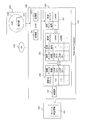
- FIG. 1 is a diagram for explaining an example of management of failure information of a virtualized server.
- the server 100 in FIG. 1 includes a POST (Power On Self Test) 110, a storage unit 120, an SP (Service Processor) 130, an HV (Hypervisor) 140, and virtual machines 150 (150-1 and 150-2).
- POST Power On Self Test
- Storage unit 120 is a storage area that can be commonly referred to by firmware installed in the server. I remember it.
- the device status information 121 is information regarding the status of various devices mounted on the server, and is stored using the HWD.
- the device status information 121 is LAN # 00-0 in the storage area of the address 100 of the storage unit 120, LAN # 00-1 in the storage area of the address 110, and LAN # 01-0 in the storage area of the address 120. Contains information about.
- the device status information 121 indicates that the status of LAN # 00-0 and LAN # 01-0 is normal (OK).
- the device state information 121 indicates that the state of LAN # 00-1 is in a failure state (NG).
- the POST 110 is firmware that automatically tests various devices mounted on the server when the server is powered on. When the POST 110 detects a device failure when the server is powered on, the POST 110 updates the device status information 121 in the storage unit 120.
- the SP 130 is firmware that controls and monitors various devices.
- the SP 130 assigns various devices set by user operations to the virtual machine 150.
- the SP 130 updates the device status information 121 in the storage unit 120.
- the HV 140 is a management program for realizing a virtual machine.
- the HV 140 is a virtualization monitor that manages the virtual machine 150-1 and the virtual machine 150-2.
- the HV 140 stores update destination information 141 that is information associating an address where device state information is stored with physical device information.
- the physical device information is information related to a device mounted on the server 100.
- the address where the device status information is stored is address information indicating where in the storage unit 120 information related to the status of each device is stored.
- Each of the virtual machine 150-1 and the virtual machine 150-2 has an OS 151 (Operation System) and operates as a virtual machine.
- the virtual machine 150 has an OBP (Open Boot Prom) 152.
- the OBP 152 serves as a BIOS in the virtual machine and is firmware that manages information on various devices assigned to the virtual machine 150.
- the information on various devices assigned to the virtual machine 150 is, for example, the virtual LAN #a and the virtual LAN #b in the virtual machine 150-1, and the virtual LAN #a in the virtual machine 150-2.
- the information on various devices assigned to the virtual machine 150 is information for identifying the virtual device.
- the same LAN card mounted on the server may be used for the virtual LAN #a of the virtual machine 150-1 and the virtual LAN #a of the virtual machine 150-2. Further, the virtual LAN #a of the virtual machine 150-1 and the virtual LAN #a of the virtual machine 150-2 may use different LAN cards.
- the virtual machine 150 detects a device failure, the virtual machine 150 stores failure information in the OBP 152.
- the virtual machine 150 cannot use devices other than the assigned device.
- the storage unit 120 is not assigned to each virtual machine 150. Therefore, the virtual machine 150-1 and the virtual machine 150-2 cannot use the storage unit 120. That is, failure information related to the virtual machine 150 is not recorded in the storage unit 120 as device state information.
- the server administrator may not be able to know all the failure information simply by referring to the device status information recorded in the storage unit 120.
- the administrator in order to collect failure information of devices installed in the server, the administrator not only stores the device status information 121 recorded in the storage unit 120 but also stores the OBP 152 installed in each virtual machine. You may have to check one by one.
- a system monitoring device that holds device status information indicating the status of hardware is provided.
- status information is stored in the system monitoring device and nonvolatile memory.
- the technology to do is known. (For example, refer to Patent Document 1).
- Patent Document 3 a technique using an inter-memory descriptor for describing a memory of another partition is known (see, for example, Patent Document 3).
- the background art described above has the following problems.
- the failure information of the devices installed in the server is not collectively managed in the virtualized server. Therefore, the operator must check the device status information and the firmware that cannot be written to the device status information one by one.
- an object of the present invention is to collectively manage failure information of devices mounted on a server.
- the information processing apparatus includes a control unit, a generation unit, a detection unit, and a notification unit.
- the generation unit generates information representing a correspondence relationship between information about the virtual machine, information about a device mounted on the information processing apparatus, and identification information for identifying the device in the virtual machine.
- the detection unit detects a failure of a device assigned to the virtual machine.
- the notification unit notifies the control unit from the virtual machine that a failure has been detected.
- the control unit includes a processing unit and a specifying unit. In response to the notification from the notification unit, the processing unit performs processing for acquiring, from the virtual machine, identification information of the device for which the detection unit has detected a failure and information regarding the virtual machine.
- the specifying unit specifies a device mounted on the information processing apparatus corresponding to the identification information acquired by the processing unit and the information related to the virtual machine, using the information generated by the generating unit.
- the control unit writes information indicating that the device specified by the specifying unit has failed in a storage area not allocated to the virtual machine.
- ⁇ Can manage the failure information of devices installed in the server collectively.
- FIG. 10 is a diagram (part 1) illustrating an example of device state information update processing; It is a figure which shows the example of the hardware constitutions of the server which concerns on this embodiment.
- FIG. 10 is a second diagram illustrating an example of device status information update processing; It is a figure explaining the example of operation
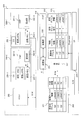
- FIG. 2 is a diagram (part 1) for explaining an example of device status information update processing.
- the server 200 in FIG. 2 includes an SP 210, a virtual machine 220, an HV 230, and a storage unit 240.
- the virtual machine 220 includes a notification unit 221 and an OBP 222.
- the HV 230 includes an HVIF 238, a specifying unit 233, and a transmission unit 237.
- An HVIF (Inter Face) 238 receives a hypervisor call sent from the virtual machine.
- the HVIF 238 includes a receiving unit 231 and a processing unit 232.
- the specifying unit 233 stores update destination information 236 in advance.
- the storage unit 240 stores device state information 241.
- the HV 230 writes failure information detected by the virtual machine 220 to the storage unit 240 that the virtual machine 220 cannot access. The writing process to the storage unit 240 of the HV 230 will be described below.
- the SP 210 activates the virtual machine 220, the SP 210 assigns various devices set by user operations to the virtual machine 220.
- the SP 210 generates physical-logical conversion information 235.
- the physical-logical conversion information 235 is information that associates the virtual machine number uniquely assigned to the virtual machine 220, the identification information of the virtual device assigned to the virtual machine 220, and the physical device mounted on the server. is there.
- the SP 210 sends the physical-logical conversion information 235 to the specifying unit 233.
- the OBP 222 detects a failure of the virtual device assigned to the virtual machine 220.
- the notification unit 221 sends a predetermined hypervisor call to the HV 230.
- the predetermined hypervisor call includes an instruction for causing the HV 230 to execute processing for writing the failure information in the storage unit 240.
- the receiving unit 231 of the HVIF 238 receives a hypervisor call.
- the processing unit 232 acquires failure information 234 that associates the virtual machine number with information about the failed virtual device.
- the processing unit 232 passes the failure information 234 to the specifying unit 233.
- the identifying unit 233 identifies, from the physical-logical conversion information 235, a physical device that matches the virtual machine number included in the failure information 234 and information regarding the failed virtual device. (10) The specifying unit 233 refers to the update destination information 236 and acquires the address information of the storage unit 240 that manages the state of the failed device. (11) The transmission unit 237 transmits failure information to the address managing the state of the failed device in the storage unit 240, and updates the device state information 241.
- the update destination information 236 is information in which information on a device mounted on the server is associated with address information indicating where the information on the state of the device is stored in the storage unit 240.
- the HV 230 may include a storage area.
- the storage area of the HV 230 stores information such as the update destination information 236, failure information 234, physical-logical conversion information 235, and the like, and may be appropriately read by the specifying unit 233.
- failure information detected by the virtual machine 220 that cannot be written to the storage unit 240 is written to the storage unit 240 by the HV 230.
- this embodiment is not limited to a server, and may be another device as long as it is an information processing device.
- FIG. 3 is a diagram illustrating an example of the hardware configuration of the server according to the present embodiment.
- the server according to the present embodiment includes a processor 11, a memory 12, a bus 13, an external storage device 14, and a network connection device 15. Further, as an option, the server may include an input / output device 16 and a medium driving device 18. It may be realized by a server, for example, a computer.
- the processor 11 can be an arbitrary processing circuit including a central processing unit (CPU).
- the processor 11 performs each process executed by the SP, POST, HV, and virtual machine.
- the processor 11 can execute, for example, a program stored in the external storage device 14.
- the memory 12 operates as a storage unit, and appropriately stores data obtained by the operation of the processor 11 and data used for processing of the processor 11.
- the network connection device 15 is used for communication with other devices, and performs communication with the management terminal 19, for example.
- the input / output device 16 is realized as, for example, a button, a keyboard, a mouse, a display, or the like.
- the bus 13 connects the processor 11, the memory 12, the input / output device 16, the external storage device 14, the medium drive device 18, and the network connection device 15 so as to exchange data with each other.
- the external storage device 14 stores programs, data, and the like, and provides the stored information to the processor 11 and the like as appropriate.
- the medium driving device 18 can output the data of the memory 12 and the external storage device 14 to the portable storage medium 19, and can read programs, data, and the like from the portable storage medium 19.
- the portable storage medium 19 may be any portable storage medium including a floppy disk, a magnetic-optical (MO) disk, a compact disc-recordable (CD-R), and a digital-versatile-disk-recordable (DVD-R). It can be a medium.
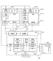
- FIG. 4 is a diagram (part 2) for explaining an example of the update process of the device status information.
- the same devices as those in FIG. 2 are given the same numbers.
- the server 200 in FIG. 4 includes an SP 210, an HV 230, a storage unit 240, a POST 250, a virtual machine 260-0, and a virtual machine 260-1.
- the SP 210 detects a failure when allocating a device mounted on the server 200 to the virtual machine 260-0 and the virtual machine 260-1
- the SP 210 updates the device status information 241 in the storage unit 240.
- the HV 230 includes an HVIF 238, a specifying unit 233, and a transmission unit 237.
- the specifying unit 233 stores device specifying information 205.
- the device identification information 205 is information including the physical-logical conversion information 235 and the update destination information 236 shown in FIG. 2, and represents the correspondence relationship between the update destination address, physical device information, virtual machine number, and virtual device information. It is. Note that the virtual machine numbers 0 and 1 correspond to the numbers at the end of the virtual machines 260-0 and 260-1, as an example.
- the storage unit 240 stores device state information 241 that is information related to the state of the device mounted on the server 200.
- the POST 250 is firmware that updates the device status information 241 in the storage unit 240 when a device failure is detected when the server 200 is powered on.
- the virtual machine 260-0 includes an OBP 261-0, a notification unit 262-0, an OS 263-0, a virtual LAN #a, a virtual LAN #b, and a virtual memory 265-0.
- the virtual machine 260-1 includes an OBP 261-1, a notification unit 262-1, an OS 263-1, a virtual LAN #a, and a virtual memory 265-1. Different LAN cards are assigned to the virtual LAN #a of the virtual machine 260-0 and the virtual LAN #a of the virtual machine 260-1.
- the device identification information 205 indicates that the virtual LAN #a of the virtual machine 260-0 is the physical LAN # 00-0, and that the virtual LAN #a of the virtual machine 260-1 is the physical LAN # 01-1. It shows the correspondence.
- the OS 263 is an OS that operates on the virtual machine 260.
- the OBP 261 When the OBP 261 detects a failure of the virtual device, the OBP 261 writes information about the virtual device in a predetermined area of the virtual memory 265.
- Virtual devices for which the OBP 261-0 detects a failure are LAN # a and LAN # b.
- the virtual device that the OBP 261-1 detects a failure is LAN # a.
- the notification unit 262 sends a hypervisor call to the HVIF 238.
- the receiving unit 231 receives a hypervisor call.
- the processing unit 232 identifies the virtual machine that has sent the hypervisor call. The process of specifying the virtual machine will be described with reference to FIG.
- the processing unit 232 acquires information regarding the failed virtual device from a predetermined area of the memory allocated to the identified virtual machine.
- the identifying unit 233 identifies, from the device identifying information 205, address information of the storage unit 240 that manages the state of the device in which the identified virtual machine information matches the failed virtual device.
- the transmission unit 237 transmits failure information to an address that manages the state of the failed device in the storage unit 240 and updates the device state information 241.
- FIG. 5 is a diagram for explaining an example of the operation of the CPU in the device status information update process.
- the same devices as those in FIG. 4 are given the same numbers.
- the virtual machine 270-0 includes a virtual CPU #a, a virtual CPU #b, a virtual LAN #a, a virtual LAN #b, a virtual memory 273-0, an OS 274-0, and an OBP 271-0.
- the virtual machine 270-1 includes a virtual CPU #a, a virtual LAN #a, a virtual memory 273-1, an OS 274-1, and an OBP 271-1.
- the HV 230 includes a specifying unit 233 and has device specifying information 280 used by the specifying unit 233.
- the device identification information 280 is information including the physical-logical conversion information 235 and the update destination information 236 shown in FIG.
- the device identification information 280 in FIG. 5 includes information about the CPU as physical / virtual device information.
- the device specifying information 280 may be information regarding a device mounted on a server such as a CPU, a memory, and a LAN, and does not limit the device.
- the OBP 271 When the OBP 271 detects a failure of the virtual device, the OBP 271 writes information on the virtual device in a predetermined area of the virtual memory 273. Note that the virtual device that the OBP 271 detects a failure may be a virtual LAN, a virtual CPU, or a virtual memory.
- the notification unit 272 sends a hypervisor call to the reception unit 231.
- the hypervisor call is processed by the virtual CPU of the virtual machine 270.
- the virtual CPU of the virtual machine 270 shifts to the HV mode.
- the virtual CPU 274 in the HV mode temporarily stops the processing of the virtual machine and performs each process executed by the HV 230.
- the virtual machine 270-1 shifts to the HV mode
- the virtual machine 270-1 temporarily stops processing.
- the virtual machine 270-0 operates with a virtual CPU that has not shifted to the HV mode.
- the virtual CPU 274 that has shifted to the HV mode performs processing executed by the HV 230.
- the processes executed by the HV 230 are the processes of the receiving unit 231, the processing unit 232, the specifying unit 233, and the transmitting unit.
- the receiving unit 231 receives a hypervisor call.
- the processing unit 232 performs processing for specifying the physical CPU number of the virtual CPU 274.
- the physical CPU number is, for example, a number such as CPU # 00-0 or CPU # 00-1 in the physical device information of the device identification information 280.
- the processing unit 232 uses the device identification information 280 to identify the virtual machine to which the virtual CPU 274 is assigned from the identified physical CPU number.
- the processing unit 232 acquires information on the failed virtual device from a predetermined area of the virtual memory 273 assigned to the identified virtual machine.
- the identifying unit 233 identifies, from the device identifying information 280, the address information of the storage unit 240 that manages the state of the device in which the virtual machine information identified by the processing unit 232 matches the failed virtual device.
- the transmission unit 237 transmits failure information to an address that manages the state of the failed device in the storage unit 240 and updates the device state information 241.
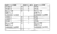
- FIG. 6 is a diagram illustrating an example of device specifying information used by the specifying unit.
- FIG. 6 is an example of physical-logical conversion information generated by the SP.
- the physical-logical conversion information is information indicating a correspondence relationship between physical device information, a virtual device number, and virtual device information.
- the physical-logical conversion information in FIG. 6 is information in which two CPUs, a memory 1 GB, and two LAN cards are assigned to virtual machine # 0.
- the physical-logical conversion information stores information of CPU # 00-0 as physical device information.
- the physical-logical conversion information indicates that the virtual machine number corresponding to CPU # 00-0 is 0 and the virtual device information is CPU #a. Similarly, the physical-logical conversion information stores information of memory 1 GB (physical addresses 0x40000000 to 0x7ffffff) as physical device information. The physical-logical conversion information indicates that the virtual machine number corresponding to the memory 1 GB (physical address 0x40000000 to 0x7ffffffffff) is 0, and the virtual device information is the memory 1 GB (virtual address 0x00000000 to 0x3ffffffff).
- FIG. 7 is a diagram illustrating an example of a memory area used by the OBP and the receiving unit.
- the virtual machine uses a partial area of the memory allocated to the virtual machine as a predetermined area used by the OBP and the receiving unit.
- the first 128 MB is used as an area for OBP
- the remaining area from 128 MB is used as an area for OS.
- the OBP binary is placed in the first 64 MB, and is used as a predetermined area (HVIF dedicated buffer) for storing the failed device information in 1 MB, and the rest is allocated as an OBP work area.
- HVIF dedicated buffer predetermined area
- FIG. 8 is a sequence diagram for explaining an example of the processing of the CPU related to the hypervisor call.
- the sequence diagram of FIG. 8 is an example of processing in which the processing unit acquires a virtual machine number and failed device information.
- FIG. 8 will be described with reference to FIGS.
- the virtual CPU #b belonging to the virtual machine # 0 executes the OBP process.
- Virtual CPU #b corresponds to physical CPU # 00-1 and executes processing on the HV side.
- the OBP When the OBP detects a failure of the virtual device, the OBP writes information on the failed virtual device in the HVIF dedicated buffer of the virtual memory (step S101).
- the notification unit of OBP sends a hypervisor call to the HV (step S102).
- the CPU shifts to the HV mode and executes the processing on the HV side.
- the virtual CPU #b acquires the physical device number.
- the physical device number of the virtual CPU #b corresponds to the physical CPU # 00-1.
- the processing unit of the HV specifies the virtual machine number from the physical device information and the virtual device information using the device specifying information (Step S103). In the device identification information, virtual CPU #b and physical CPU # 00-1 are associated with virtual machine # 0.
- the processing unit acquires information regarding the failed device from the HVIF dedicated buffer of the virtual machine # 0 (step S104).
- the physical CPU # 00-1 acquires information on the failed device from the HVIF dedicated buffer having the physical address 0x44000000.
- the specifying unit specifies, from the device specifying information, the address information of the storage unit that manages the state of the device in which the virtual machine information specified by the processing unit matches the failed virtual device.
- the transmission unit transmits failure information to an address that manages the state of the failed device in the storage unit, and updates the device state information (step S105).
- the physical CPU # 00-1 executes a return command for operating as the virtual CPU #b (step S106).
- the physical CPU # 00-1 operates on the OBP side as the virtual CPU #b (step S107).
- FIG. 9 is a flowchart for explaining an example of SP processing relating to physical-logical conversion information.
- the SP When performing processing for assigning various devices to the virtual machine, the SP generates physical-logical conversion information (step S201). The SP sends physical-logical conversion information to the specifying unit (step S202). The SP ends the process.
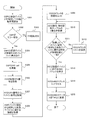
- FIG. 10 is a flowchart illustrating an example of OBP and HV processing related to device status information update processing.
- the OBP designates a virtual device used by the virtual machine and activates the OS (step S301).
- the OBP determines whether an error has occurred regarding the designated virtual device (step S302). If the OBP detects no error, the OS has been successfully started (NO in step S303 and step S302).
- the OBP writes information on the virtual device in which the error is detected in the HVIF dedicated buffer (YES in step S304 and step S302).
- the notification unit of OBP transmits a hypervisor call to the HV (step S305).
- the processing unit of the HV acquires the physical device number of the CPU that executed the processes of S301 to S305 (step S306).
- the processing unit of the HV acquires the virtual machine number from the physical device number using the device identification information (step S307).
- the processing unit of the HV acquires information regarding the failed virtual device from the HVIF specialized buffer in the memory allocated to the virtual machine acquired in S307 (step S308).
- the HV identification unit initializes the counter n (step S309).
- the HV identification unit refers to the column of the nth row of the device identification information (step S310).
- the HV identification unit determines whether the information regarding the failed virtual device acquired in S308 and the virtual machine number acquired in S307 match the device identification information in the n-th row (step S311).
- the HV identification unit adds 1 to the counter n (NO in step S312 and step S311).
- the specifying unit of the HV specifies the address information of the storage unit that manages the state of the physical device corresponding to the failed virtual device (step S313).
- the transmission unit of the HV transmits failure information to the identified address of the storage unit (step S314).
- the HV sets the state of the address managing the state of the failed physical device to NG (step S315).
- the HV that can access the storage unit updates the device state information stored in the storage unit. Can do.
Landscapes
- Engineering & Computer Science (AREA)
- Theoretical Computer Science (AREA)
- Quality & Reliability (AREA)
- Physics & Mathematics (AREA)
- General Engineering & Computer Science (AREA)
- General Physics & Mathematics (AREA)
- Hardware Redundancy (AREA)
- Debugging And Monitoring (AREA)
Abstract
La présente invention concerne un dispositif de traitement d'informations qui comporte une unité de commande, une unité de génération, une unité de détection et une unité de notification. L'unité de génération génère des informations indiquant la relation de correspondance entre des informations concernant des machines virtuelles, des informations concernant des dispositifs mis en œuvre dans le dispositif de traitement d'informations, et des informations d'identification identifiant des dispositifs, qui sont utilisés dans les machines virtuelles. L'unité de détection détecte un dysfonctionnement de chaque dispositif affecté aux machines virtuelles. L'unité de notification envoie une notification de détection d'un dysfonctionnement d'une machine virtuelle à l'unité de commande. L'unité de commande comporte une unité de traitement et une unité d'identification. L'unité de traitement reçoit la notification à partir de l'unité de notification et réalise un traitement pour obtenir, à partir de la machine virtuelle, des informations concernant la machine virtuelle et des informations d'identification concernant le dispositif présentant le dysfonctionnement détecté par l'unité de détection. L'unité d'identification identifie, à l'aide des informations générées par l'unité de génération, le dispositif qui est mis en œuvre dans le dispositif de traitement d'informations et qui correspond à la fois aux informations concernant la machine virtuelle et aux informations d'identification obtenues par l'unité de traitement. L'unité de commande écrit, dans une région de stockage qui n'a pas été affectée aux machines virtuelles, des informations indiquant que le dispositif identifié par l'unité d'identification présente un dysfonctionnement.
Priority Applications (1)
| Application Number | Priority Date | Filing Date | Title |
|---|---|---|---|
| PCT/JP2013/066891 WO2014203360A1 (fr) | 2013-06-19 | 2013-06-19 | Dispositif de traitement d'informations, procédé de traitement d'informations et programme de traitement d'informations |
Applications Claiming Priority (1)
| Application Number | Priority Date | Filing Date | Title |
|---|---|---|---|
| PCT/JP2013/066891 WO2014203360A1 (fr) | 2013-06-19 | 2013-06-19 | Dispositif de traitement d'informations, procédé de traitement d'informations et programme de traitement d'informations |
Publications (1)
| Publication Number | Publication Date |
|---|---|
| WO2014203360A1 true WO2014203360A1 (fr) | 2014-12-24 |
Family
ID=52104122
Family Applications (1)
| Application Number | Title | Priority Date | Filing Date |
|---|---|---|---|
| PCT/JP2013/066891 Ceased WO2014203360A1 (fr) | 2013-06-19 | 2013-06-19 | Dispositif de traitement d'informations, procédé de traitement d'informations et programme de traitement d'informations |
Country Status (1)
| Country | Link |
|---|---|
| WO (1) | WO2014203360A1 (fr) |
Cited By (1)
| Publication number | Priority date | Publication date | Assignee | Title |
|---|---|---|---|---|
| WO2022009438A1 (fr) * | 2020-07-10 | 2022-01-13 | 日本電信電話株式会社 | Dispositif, système, procédé de commande de système, et programme de maintenance de serveur |
Citations (1)
| Publication number | Priority date | Publication date | Assignee | Title |
|---|---|---|---|---|
| WO2012137239A1 (fr) * | 2011-04-04 | 2012-10-11 | 株式会社日立製作所 | Système informatique |
-
2013
- 2013-06-19 WO PCT/JP2013/066891 patent/WO2014203360A1/fr not_active Ceased
Patent Citations (1)
| Publication number | Priority date | Publication date | Assignee | Title |
|---|---|---|---|---|
| WO2012137239A1 (fr) * | 2011-04-04 | 2012-10-11 | 株式会社日立製作所 | Système informatique |
Cited By (3)
| Publication number | Priority date | Publication date | Assignee | Title |
|---|---|---|---|---|
| WO2022009438A1 (fr) * | 2020-07-10 | 2022-01-13 | 日本電信電話株式会社 | Dispositif, système, procédé de commande de système, et programme de maintenance de serveur |
| JPWO2022009438A1 (fr) * | 2020-07-10 | 2022-01-13 | ||
| JP7405260B2 (ja) | 2020-07-10 | 2023-12-26 | 日本電信電話株式会社 | サーバメンテナンス制御装置、システム、制御方法及びプログラム |
Similar Documents
| Publication | Publication Date | Title |
|---|---|---|
| JP5068056B2 (ja) | 障害回復方法、計算機システム及び管理サーバ | |
| EP2624133B1 (fr) | Automatisation de récupération prenant en compte la topologie du réseau | |
| US9489274B2 (en) | System and method for performing efficient failover and virtual machine (VM) migration in virtual desktop infrastructure (VDI) | |
| JP4544146B2 (ja) | 障害回復方法 | |
| US9912535B2 (en) | System and method of performing high availability configuration and validation of virtual desktop infrastructure (VDI) | |
| JP6946867B2 (ja) | 情報処理装置、管理装置およびプログラム | |
| US20040225929A1 (en) | Preservation of error data on a diskless platform | |
| CA2804379C (fr) | Automatisation de la recuperation dans des environnements heterogenes | |
| JP2008140198A (ja) | フェイルオーバ方法、およびその計算機システム。 | |
| JPWO2013094048A1 (ja) | 試験サーバ、情報処理システム、試験プログラムおよび試験方法 | |
| WO2016115661A1 (fr) | Procédé et dispositif d'isolement de défaillance de mémoire | |
| JP2016518654A (ja) | サーバ制御方法及びサーバ制御装置 | |
| CN101373448B (zh) | 具有远程管理的计算机系统 | |
| WO2015114816A1 (fr) | Ordinateur de gestion et programme de gestion | |
| JP2013161210A (ja) | 情報処理装置、情報取得方法、及びプログラム | |
| JP5078592B2 (ja) | フェイルオーバーを行わせる方法 | |
| CN103403688A (zh) | 处理器管理方法 | |
| WO2014203360A1 (fr) | Dispositif de traitement d'informations, procédé de traitement d'informations et programme de traitement d'informations | |
| JP2010146087A (ja) | 系切替計算機システムの管理方法 | |
| JP2015122030A (ja) | 情報処理装置、監視プログラム及び監視方法 | |
| CN107147516B (zh) | 服务器、存储系统及相关方法 | |
| JP5266347B2 (ja) | 引継方法、計算機システム及び管理サーバ | |
| CN108376087A (zh) | 一种电子设备的启动控制方法、装置及服务器 | |
| TW200307200A (en) | Multiple fault location in a series of devices | |
| WO2010023756A1 (fr) | Processeur d’informations comprenant un processeur virtuel, procédé de traitement d’informations, et programme |
Legal Events
| Date | Code | Title | Description |
|---|---|---|---|
| 121 | Ep: the epo has been informed by wipo that ep was designated in this application |
Ref document number: 13887062 Country of ref document: EP Kind code of ref document: A1 |
|
| NENP | Non-entry into the national phase |
Ref country code: DE |
|
| 122 | Ep: pct application non-entry in european phase |
Ref document number: 13887062 Country of ref document: EP Kind code of ref document: A1 |
|
| NENP | Non-entry into the national phase |
Ref country code: JP |