WO2014203578A1 - 作業装置 - Google Patents
作業装置 Download PDFInfo
- Publication number
- WO2014203578A1 WO2014203578A1 PCT/JP2014/058199 JP2014058199W WO2014203578A1 WO 2014203578 A1 WO2014203578 A1 WO 2014203578A1 JP 2014058199 W JP2014058199 W JP 2014058199W WO 2014203578 A1 WO2014203578 A1 WO 2014203578A1
- Authority
- WO
- WIPO (PCT)
- Prior art keywords
- contact
- movable
- receiving portion
- working
- contact receiving
- Prior art date
- Legal status (The legal status is an assumption and is not a legal conclusion. Google has not performed a legal analysis and makes no representation as to the accuracy of the status listed.)
- Ceased
Links
Images

















Classifications
-
- B—PERFORMING OPERATIONS; TRANSPORTING
- B25—HAND TOOLS; PORTABLE POWER-DRIVEN TOOLS; MANIPULATORS
- B25B—TOOLS OR BENCH DEVICES NOT OTHERWISE PROVIDED FOR, FOR FASTENING, CONNECTING, DISENGAGING, OR HOLDING
- B25B5/00—Clamps
- B25B5/06—Arrangements for positively actuating jaws
-
- B—PERFORMING OPERATIONS; TRANSPORTING
- B25—HAND TOOLS; PORTABLE POWER-DRIVEN TOOLS; MANIPULATORS
- B25B—TOOLS OR BENCH DEVICES NOT OTHERWISE PROVIDED FOR, FOR FASTENING, CONNECTING, DISENGAGING, OR HOLDING
- B25B5/00—Clamps
- B25B5/02—Clamps with sliding jaws
-
- B—PERFORMING OPERATIONS; TRANSPORTING
- B25—HAND TOOLS; PORTABLE POWER-DRIVEN TOOLS; MANIPULATORS
- B25B—TOOLS OR BENCH DEVICES NOT OTHERWISE PROVIDED FOR, FOR FASTENING, CONNECTING, DISENGAGING, OR HOLDING
- B25B5/00—Clamps
- B25B5/06—Arrangements for positively actuating jaws
- B25B5/08—Arrangements for positively actuating jaws using cams
-
- B—PERFORMING OPERATIONS; TRANSPORTING
- B25—HAND TOOLS; PORTABLE POWER-DRIVEN TOOLS; MANIPULATORS
- B25B—TOOLS OR BENCH DEVICES NOT OTHERWISE PROVIDED FOR, FOR FASTENING, CONNECTING, DISENGAGING, OR HOLDING
- B25B5/00—Clamps
- B25B5/16—Details, e.g. jaws, jaw attachments
-
- B—PERFORMING OPERATIONS; TRANSPORTING
- B25—HAND TOOLS; PORTABLE POWER-DRIVEN TOOLS; MANIPULATORS
- B25B—TOOLS OR BENCH DEVICES NOT OTHERWISE PROVIDED FOR, FOR FASTENING, CONNECTING, DISENGAGING, OR HOLDING
- B25B7/00—Pliers; Other hand-held gripping tools with jaws on pivoted limbs; Details applicable generally to pivoted-limb hand tools
- B25B7/14—Locking means
-
- B—PERFORMING OPERATIONS; TRANSPORTING
- B25—HAND TOOLS; PORTABLE POWER-DRIVEN TOOLS; MANIPULATORS
- B25B—TOOLS OR BENCH DEVICES NOT OTHERWISE PROVIDED FOR, FOR FASTENING, CONNECTING, DISENGAGING, OR HOLDING
- B25B7/00—Pliers; Other hand-held gripping tools with jaws on pivoted limbs; Details applicable generally to pivoted-limb hand tools
- B25B7/18—Adjusting means for the operating arms
-
- F—MECHANICAL ENGINEERING; LIGHTING; HEATING; WEAPONS; BLASTING
- F16—ENGINEERING ELEMENTS AND UNITS; GENERAL MEASURES FOR PRODUCING AND MAINTAINING EFFECTIVE FUNCTIONING OF MACHINES OR INSTALLATIONS; THERMAL INSULATION IN GENERAL
- F16C—SHAFTS; FLEXIBLE SHAFTS; ELEMENTS OR CRANKSHAFT MECHANISMS; ROTARY BODIES OTHER THAN GEARING ELEMENTS; BEARINGS
- F16C1/00—Flexible shafts; Mechanical means for transmitting movement in a flexible sheathing
- F16C1/10—Means for transmitting linear movement in a flexible sheathing, e.g. "Bowden-mechanisms"
- F16C1/12—Arrangements for transmitting movement to or from the flexible member
- F16C1/14—Construction of the end-piece of the flexible member; Attachment thereof to the flexible member
-
- F—MECHANICAL ENGINEERING; LIGHTING; HEATING; WEAPONS; BLASTING
- F16—ENGINEERING ELEMENTS AND UNITS; GENERAL MEASURES FOR PRODUCING AND MAINTAINING EFFECTIVE FUNCTIONING OF MACHINES OR INSTALLATIONS; THERMAL INSULATION IN GENERAL
- F16H—GEARING
- F16H37/00—Combinations of mechanical gearings, not provided for in groups F16H1/00 - F16H35/00
- F16H37/12—Gearings comprising primarily toothed or friction gearing, links or levers, and cams, or members of at least two of these types
Definitions
- the present invention relates to a working device that performs a predetermined work by operating a working part when a first member or a second member is moved by an applied force and a force is transmitted.
- Patent Document 1 Japanese Patent No. 4999961
- the opening / closing work tool disclosed in Patent Document 1 pivotally attaches a pair of first half and second half together in the middle, and the first half and the second half are opposed to each other.
- a closing force that pushes the proximal ends of the first half and the second half facing each other in the inward closing direction, with the distal end portion serving as a clamping portion or a cutting portion.
- An opening / closing operation unit that closes or cuts an object by closing an opening / closing operation unit of the tip part, and the tip of the first half and the tip of the second half serving as the opening / closing operation unit
- the closing force is further applied to the opening / closing operation unit with the object sandwiched therebetween
- at least the proximal end portion of the first half body or the proximal end portion of the second half body corresponds to the increase in the closing force. It is configured to bend inwardly, and the opening / closing operation is performed between the contact portion movable by the bend and the receiving portion with which the contact portion abuts. The contact portion is bent and moved by increasing the closing force so as to approach the receiving portion.
- the contact portion When the closing force reaches a predetermined value, the contact portion is moved to the receiving portion. Even if the closing force applied to the opening / closing operation portion continues to increase further, the proximal end side of the contact portion further bends or moves inward as the closing force increases. The increasing closing force is not transmitted to the opening / closing operation unit, and the clamping force for clamping the object or the cutting force for cutting the object is determined by the opening / closing operation unit when the receiving unit abuts on the contact unit.
- It is configured so that it does not exceed the pinching force or cutting force that becomes the peak value according to the closing force applied to the surface, and does not want to be crushed by the pinching operation, does not want to break, or does not want to scratch the surface Hold or cut objects with delicate structures such as objects
- the operator simply adjusts the closing force applied to the opening / closing operation part by adjusting the delicate force, and does not carefully operate the opening / closing operation part.
- the object can be easily sandwiched or cut without being crushed, damaged, or scratched by an extremely simple operation.
- the present applicant solves the above-mentioned problems, and adapts the technological invention of Patent Document 1 to various uses such as pressing, tightening, stirring, etc., as well as opening and closing work tools for pinching and cutting applications.
- the maximum value (peak value) of the force acting on the object during work such as clamping force and cutting force, changes even if the size and thickness of the object to be worked change.
- a technological work device that can perform predetermined work without exerting a force exceeding a certain value, and that has been applied not only to clamping and cutting but also to pressing, tightening, stirring, etc. developed.
- the first member 1 and the second member 2 are provided, and at least one of them is movably provided, and the first member 1 or the second member 2 is moved by the applied force to transmit the force and act as predetermined.
- a movable factor part 4 and a movable contact part 5 movable by deformation of the movable factor part 4 are provided on one of the first member 1 and the second member 2.
- a contact receiving portion 6 with which the movable contact portion 5 contacts is provided, and the movable contact portion 5 does not move close to the contact receiving portion 6 until an operating resistance is generated in the working portion 3.
- the relative movement is caused by deformation of the movable factor 4.
- the contact receiving unit 6 is deformed.
- the movable contact portion 5 is configured so as to come into contact with the contact receiving portion 6 when the distance to the portion 6 is narrowed and approaches the contact receiving portion 6 and the operating resistance of the working portion 3 reaches a predetermined value.
- the movable contact portion 5 When the movable contact portion 5 is in contact with the contact receiving portion 6, the first member 1 or the second member 2 provided movably after the movable contact portion 5 is in contact with the contact receiving portion 6. Further, the applied force is not transmitted to the working unit 3, or after the movable contact part 5 contacts the contact receiving part 6, the first member 1 or the second member 2 provided movably is provided. When a further force is applied, the movable contact portion 5 has a transmission ratio that transmits the applied force to the working portion 3. Those of the working device, characterized in that the abutting receiving part 6 is configured to subtract than the previous transmission ratio abuts.
- the movable factor portion 4 is made of an elastic body, and when the operating resistance of the working unit 3 reaches a predetermined value, the movable factor portion 4 is elastically deformed by a predetermined amount, and the movable contact portion 5 becomes the contact receiving portion.
- the movable return portion 4 is elastically restored to return the movable portion.
- the abutment surface 6A of the abutment receiving portion 6 with which the movable abutment portion 5 abuts or the abutment surface 5A of the movable abutment portion 5 with which the abutment receiving portion 6 abuts is provided movably.
- the movable contact portion 5 is extended along the moving direction of the first member 1 or the second member 2 and the movable contact portion 5 is in contact with the contact surface 6A of the contact receiving portion 6 until an operating resistance is generated in the working portion 3.
- the contact receiving portion 6 moves relative to the contact surface 5A of the movable contact portion 5 in the adjacent state, and an operating resistance is generated in the working portion 3.
- the movable contact portion 5 stops the relative movement and moves in a direction different from the relative movement direction and approaches the contact receiving portion 6, or the movable contact portion 5 moves while making the relative movement. It is configured to move in a direction different from the relative movement direction and to approach the contact receiving portion 6.
- the abutment surface 6A of the abutment receiving portion 6 with which the movable abutment portion 5 abuts or the abutment surface 5A of the movable abutment portion 5 with which the abutment receiving portion 6 abuts is provided movably.
- the movable contact portion 5 is extended along the moving direction of the first member 1 or the second member 2 and the movable contact portion 5 is in contact with the contact surface 6A of the contact receiving portion 6 until an operating resistance is generated in the working portion 3.
- the contact receiving portion 6 moves relative to the contact surface 5A of the movable contact portion 5 in the adjacent state, and an operating resistance is generated in the working portion 3.
- the movable contact portion 5 stops the relative movement and moves in a direction different from the relative movement direction and approaches the contact receiving portion 6, or the movable contact portion 5 moves while making the relative movement. It is configured to move in a direction different from the relative movement direction and to approach the contact receiving portion 6.
- a plurality of concave portions or convex portions are arranged on the contact surface 6A of the contact receiving portion 6 along the length direction of the contact surface 6A, and the contact portion 6 contacts the movable contact portion 5.
- a convex portion or a concave portion that fits into the concave portion or convex portion provided on the contact surface 6A is provided, or a concave portion or a convex portion is provided on the contact surface 5A of the movable contact portion 5 along the length direction of the contact surface 5A.
- a plurality of portions are arranged side by side, and the contact receiving portion 6 is provided with a recess provided on the contact surface 5A of the movable contact portion 5 or a protrusion or recess that fits with the protrusion.
- the movable contact portion 5 is configured to be engaged with the contact receiving portion 6 so as to be engaged with the contact receiving portion 6 when the movable contact portion 5 contacts the contact receiving portion 6.
- a plurality of concave portions or convex portions are arranged on the contact surface 6A of the contact receiving portion 6 along the length direction of the contact surface 6A, and the contact portion 6 contacts the movable contact portion 5.
- a convex portion or a concave portion that fits into the concave portion or convex portion provided on the contact surface 6A is provided, or a concave portion or a convex portion is provided on the contact surface 5A of the movable contact portion 5 along the length direction of the contact surface 5A.
- a plurality of portions are arranged side by side, and the contact receiving portion 6 is provided with a recess provided on the contact surface 5A of the movable contact portion 5 or a protrusion or recess that fits with the protrusion.
- the movable contact portion 5 is configured to be engaged with the contact receiving portion 6 so as to be engaged with the contact receiving portion 6 when the movable contact portion 5 contacts the contact receiving portion 6.
- a plurality of concave portions or convex portions are arranged on the contact surface 6A of the contact receiving portion 6 along the length direction of the contact surface 6A, and the contact portion 6 contacts the movable contact portion 5.
- a convex portion or a concave portion that fits into the concave portion or convex portion provided on the contact surface 6A is provided, or a concave portion or a convex portion is provided on the contact surface 5A of the movable contact portion 5 along the length direction of the contact surface 5A.
- a plurality of portions are arranged side by side, and the contact receiving portion 6 is provided with a recess provided on the contact surface 5A of the movable contact portion 5 or a protrusion or recess that fits with the protrusion.
- the movable contact portion 5 is configured to be engaged with the contact receiving portion 6 so as to be engaged with the contact receiving portion 6 when the movable contact portion 5 contacts the contact receiving portion 6.
- a plurality of concave portions or convex portions are arranged on the contact surface 6A of the contact receiving portion 6 along the length direction of the contact surface 6A, and the contact portion 6 contacts the movable contact portion 5.
- a convex portion or a concave portion that fits into the concave portion or convex portion provided on the contact surface 6A is provided, or a concave portion or a convex portion is provided on the contact surface 5A of the movable contact portion 5 along the length direction of the contact surface 5A.
- a plurality of portions are arranged side by side, and the contact receiving portion 6 is provided with a recess provided on the contact surface 5A of the movable contact portion 5 or a protrusion or recess that fits with the protrusion.
- the movable contact portion 5 is configured to be engaged with the contact receiving portion 6 so as to be engaged with the contact receiving portion 6 when the movable contact portion 5 contacts the contact receiving portion 6.
- the contact surface 6A of the contact receiving portion 6 is provided with a synthetic resin or rubber having elasticity, and the movable contact portion 5 is configured to contact the synthetic resin or rubber having elasticity, or the movable contact
- An elastic synthetic resin or rubber is provided on the contact surface 5A of the contact portion 5, and the contact receiving portion 6 is configured to contact the elastic synthetic resin or rubber so that the movable contact portion 5 is When contacting the contact receiving part 6, a frictional force is generated between the movable contact part 5 and the contact receiving part 6, and further applied after the movable contact part 5 contacts the contact receiving part 6. 2.
- the transmission ratio for transmitting the applied force to the working part 3 is reduced as compared with the transmission ratio before the movable contact part 5 contacts the contact receiving part 6. This relates to the working device described.
- the contact surface 6A of the contact receiving portion 6 is provided with a synthetic resin or rubber having elasticity, and the movable contact portion 5 is configured to contact the synthetic resin or rubber having elasticity, or the movable contact
- An elastic synthetic resin or rubber is provided on the contact surface 5A of the contact portion 5, and the contact receiving portion 6 is configured to contact the elastic synthetic resin or rubber so that the movable contact portion 5 is When contacting the contact receiving part 6, a frictional force is generated between the movable contact part 5 and the contact receiving part 6, and further applied after the movable contact part 5 contacts the contact receiving part 6. 3.
- the transmission ratio for transmitting the applied force to the working part 3 is reduced as compared with the transmission ratio before the movable contact part 5 contacts the contact receiving part 6. This relates to the working device described.
- the contact surface 6A of the contact receiving portion 6 is provided with a synthetic resin or rubber having elasticity, and the movable contact portion 5 is configured to contact the synthetic resin or rubber having elasticity, or the movable contact
- An elastic synthetic resin or rubber is provided on the contact surface 5A of the contact portion 5, and the contact receiving portion 6 is configured to contact the elastic synthetic resin or rubber so that the movable contact portion 5 is When contacting the contact receiving part 6, a frictional force is generated between the movable contact part 5 and the contact receiving part 6, and further applied after the movable contact part 5 contacts the contact receiving part 6. 4.
- the transmission ratio for transmitting the applied force to the working part 3 is reduced as compared with the transmission ratio before the movable contact part 5 contacts the contact receiving part 6. This relates to the working device described.
- the contact surface 6A of the contact receiving portion 6 is provided with a synthetic resin or rubber having elasticity, and the movable contact portion 5 is configured to contact the synthetic resin or rubber having elasticity, or the movable contact
- An elastic synthetic resin or rubber is provided on the contact surface 5A of the contact portion 5, and the contact receiving portion 6 is configured to contact the elastic synthetic resin or rubber so that the movable contact portion 5 is When contacting the contact receiving part 6, a frictional force is generated between the movable contact part 5 and the contact receiving part 6, and further applied after the movable contact part 5 contacts the contact receiving part 6. 5.
- the transmission ratio for transmitting the applied force to the working part 3 is reduced as compared with the transmission ratio before the movable contact part 5 contacts the contact receiving part 6. This relates to the working device described.
- the movable contact unit 5 approaches the contact receiving unit 6 positioned in a direction substantially orthogonal to the relative movement direction due to deformation of the movable factor unit 4.
- the movable contact unit 5 approaches the contact receiving unit 6 positioned in a direction substantially orthogonal to the relative movement direction due to deformation of the movable factor unit 4.
- the movable contact portion 5 includes a lock mechanism that holds the contact state of the movable contact portion 5 with the contact receiving portion 6. After the movable contact portion 5 contacts the contact receiving portion 6, the lock mechanism Even if force is not continuously applied, the contact state of the movable contact portion 5 with the contact receiving portion 6 is maintained, and the force exerted by the working portion 3 is maintained in a constant state.
- the working apparatus according to any one of claims 1 to 12.
- the movable contact portion 5 includes a lock mechanism that holds the contact state of the movable contact portion 5 with the contact receiving portion 6. After the movable contact portion 5 contacts the contact receiving portion 6, the lock mechanism Even if force is not continuously applied, the contact state of the movable contact portion 5 with the contact receiving portion 6 is maintained, and the force exerted by the working portion 3 is maintained in a constant state.
- the working apparatus according to claim 13.
- the movable contact portion 5 includes a lock mechanism that holds the contact state of the movable contact portion 5 with the contact receiving portion 6. After the movable contact portion 5 contacts the contact receiving portion 6, the lock mechanism Even if force is not continuously applied, the contact state of the movable contact portion 5 with the contact receiving portion 6 is maintained, and the force exerted by the working portion 3 is maintained in a constant state.
- the working apparatus according to claim 14.
- the movable contact portion 5 includes a lock mechanism that holds the contact state of the movable contact portion 5 with the contact receiving portion 6. After the movable contact portion 5 contacts the contact receiving portion 6, the lock mechanism Even if force is not continuously applied, the contact state of the movable contact portion 5 with the contact receiving portion 6 is maintained, and the force exerted by the working portion 3 is maintained in a constant state.
- a movable factor deformation prevention mechanism that inhibits the deformation of the movable factor part 4 is provided, and the movable factor part 4 is activated even when an operating resistance is generated in the working unit 3 by operating the movable factor deformation preventing mechanism.
- a movable factor deformation prevention mechanism that inhibits the deformation of the movable factor part 4 is provided, and the movable factor part 4 is activated even when an operating resistance is generated in the working unit 3 by operating the movable factor deformation preventing mechanism.
- a movable factor deformation prevention mechanism that inhibits the deformation of the movable factor part 4 is provided, and the movable factor part 4 is activated even when an operating resistance is generated in the working unit 3 by operating the movable factor deformation preventing mechanism.
- the working device is configured not to be deformed.
- a movable factor deformation prevention mechanism that inhibits the deformation of the movable factor part 4 is provided, and the movable factor part 4 is activated even when an operating resistance is generated in the working unit 3 by operating the movable factor deformation preventing mechanism.
- a movable factor deformation prevention mechanism that inhibits the deformation of the movable factor part 4 is provided, and the movable factor part 4 is activated even when an operating resistance is generated in the working unit 3 by operating the movable factor deformation preventing mechanism.
- a movable factor deformation prevention mechanism that inhibits the deformation of the movable factor part 4 is provided, and the movable factor part 4 is activated even when an operating resistance is generated in the working unit 3 by operating the movable factor deformation preventing mechanism.
- a movable factor deformation prevention mechanism that inhibits the deformation of the movable factor part 4 is provided, and the movable factor part 4 is activated even when an operating resistance is generated in the working unit 3 by operating the movable factor deformation preventing mechanism. 19.
- a movable factor deformation prevention mechanism that inhibits the deformation of the movable factor part 4 is provided, and the movable factor part 4 is activated even when an operating resistance is generated in the working unit 3 by operating the movable factor deformation preventing mechanism.
- the working device is configured not to be deformed.
- a predetermined work can be performed without applying a force greater than or equal to a predetermined value to an object to perform a predetermined work, or a working portion is provided on one or both of a first member and a second member that are movably provided.
- the direction in which the movable contact portion approaches the contact receiving portion is different from the direction in which the movable contact portion moves relative to the contact receiving portion.
- the present invention is not limited to the clamping and cutting operations as in the conventional example, and is not conventionally possible to realize adaptation to a working device for performing various operations such as expansion, pressing, tightening, stirring, and the like. It becomes a revolutionary working device.
- FIG. 1 is an explanatory perspective view illustrating Example 1.
- FIG. FIG. 6 is an operation explanatory diagram before operating resistance is generated in the working unit of the first embodiment.
- FIG. 6 is an operation explanatory diagram after an operating resistance is generated in the working unit of the first embodiment.
- 6 is an explanatory front view showing Example 2.
- FIG. FIG. 9 is an enlarged explanatory cross-sectional view showing a contact receiving portion of Embodiment 3. It is explanatory drawing which shows the state before the lock mechanism of Example 4 act
- FIG. 10 is an explanatory front view illustrating a state where an operating resistance is generated in the working unit of Example 5 and the movable contact portion is in contact with the contact receiving portion.
- FIG. 10 is an explanatory front view showing a state in which the working resistance of the working unit is further increased from the state of FIG. 9.
- 10 is a perspective view showing Example 6.
- FIG. 10 is an operation explanatory diagram before operating resistance is generated in the working unit of Example 6
- FIG. 10 is an operation explanatory diagram after an operating resistance is generated in the working unit of Example 6
- 10 is an explanatory front view showing Example 7.
- FIG. It is a front view which shows the state before an operating resistance arises in the working part of Example 8.
- FIG. 10 is an explanatory front view illustrating a state where an operating resistance is generated in the working unit of Example 5 and the movable contact portion is in contact with the contact receiving portion.
- FIG. 10 is an explanatory front view showing a state in which the working resistance of the working unit is further increased from
- FIG. 16 is an explanatory front view showing a state where an operating resistance is generated in the working portion of Example 8 and the movable contact portion is in contact with the contact receiving portion.
- FIG. 10 is an enlarged cross-sectional view illustrating a lock mechanism according to an eighth embodiment.
- FIG. 10 is an enlarged cross-sectional view illustrating a lock mechanism according to an eighth embodiment.
- 10 is a front view showing Example 9.
- FIG. 10 is an operation explanatory diagram of Embodiment 9.
- FIG. FIG. 10 is an enlarged explanatory sectional view showing a lock mechanism of Example 9.
- 10 is a front view showing Example 10.
- FIG. 10 is an explanatory front view showing Example 11. It is explanatory drawing which shows the movable factor deformation
- FIG. 10 is an explanatory drawing which shows the movable factor deformation
- FIG. 22 is an enlarged explanatory view showing a movable factor part of Example 13. It is an enlarged explanatory view showing another example of the movable factor part of Example 13. It is the explanation perspective view which notched a part which shows Example 14.
- FIG. FIG. 25 is an explanatory plan view showing a state before an operating resistance is generated in the working part of Example 14;
- FIG. 29 is an explanatory plan view showing a state where an operating resistance is generated in the working portion of Example 14 and the movable contact portion is in contact with the contact receiving portion.
- FIG. 16 is a perspective view showing Example 15.
- FIG. 29 is an enlarged explanatory sectional view showing a state before an operating resistance is generated in the working part of Example 15; It is explanatory drawing which shows the use condition of Example 15.
- FIG. 17 is an enlarged explanatory cross-sectional view showing a state in which an operating resistance is generated in the working portion of Example 15 and the movable contact portion is in contact with the contact receiving portion.
- FIG. 16 is an explanatory perspective view showing Example 16;
- FIG. 16 is an explanatory exploded perspective view showing Example 16; It is an enlarged explanatory view showing a state before an operating resistance is generated in the working part of Example 16.
- FIG. 18 is an enlarged explanatory view showing a state where an operating resistance is generated in the working part of Example 16 and the movable contact part is in contact with the contact receiving part.
- FIG. 16 is an explanatory perspective view showing Example 17.
- 18 is an explanatory exploded perspective view showing Example 17.
- FIG. 18 is an enlarged explanatory view showing a state where the suction resistance of Example 17 reaches a predetermined value and the movable contact portion comes into contact with the contact receiving portion.
- FIG. 20 is an explanatory perspective view showing Example 18;
- FIG. 29 is an enlarged explanatory view showing a state before an operating resistance is generated in the working part of Example 18.
- FIG. 29 is an enlarged explanatory view showing a state where an operating resistance is generated in the working portion of Example 18 and the movable contact portion is in contact with the contact receiving portion.
- 20 is a perspective view showing Example 19.
- FIG. 20 is a perspective view showing another example of the nineteenth embodiment.
- the working member 3 is operated by the relative movement of the first member 1 and the second member 2, or the first member 1 and the second member 2 move in the same direction while maintaining a constant distance.
- the working unit 3 can be configured to operate.
- the working unit 3 When the working unit 3 is configured to operate by the relative movement of the first member 1 and the second member 2, a force is applied to one or both of the first member 1 and the second member 2 that are provided movably. When applied, the first member 1 and the second member 2 move relative to each other, the force applied by the relative movement of the first member 1 and the second member 2 is transmitted, and the working unit 3 is activated. Until the working resistance is generated in the working part 3, the movable contact part 5 provided on one of the first member 1 and the second member 2 and the other are moved along with the relative movement of the first member 1 and the second member 2. The provided contact receiving portion 6 moves relative to each other.
- the amount of movement of the first member 1 and the second member 2 at the time of relative movement varies depending on the size and thickness of the object 7 on which the work unit 3 performs a predetermined work.
- the relative movement amount with respect to the contact portion 6 also changes.
- the movable factor part 4 provided with the movable contact part 5 on one of the first member 1 and the second member 2 is deformed.
- the contact portion 5 moves in a direction approaching the contact receiving portion 6.
- the operating resistance of the working unit 3 in the present invention means a force exerted on the object 7 by the working unit 3.
- the working unit 3 moves the object 7.
- the present invention when configured as a pressing device, it means a pressing force by which the working unit 3 presses the object, and when the working unit 3 is configured as a cutting device, the cutting force and the expansion force are defined.
- an opening device it means a spreading force
- when configured as a clamping device it means a clamping force
- stirring device it means a stirring force.
- the movable contact portion 5 moves closer to the contact receiving portion 6, the movable contact portion 5 moves in a direction different from the moving direction before the operating resistance is generated in the working portion 3 and approaches the contact receiving portion 6.
- the amount of deformation of the movable factor part 4 increases and the movable contact part 5 further approaches the contact receiving part 6, so that the operating resistance of the working part 3 becomes a predetermined value.
- the movable contact portion 5 contacts the contact receiving portion 6.
- the transmission ratio that transmits the applied force to the working unit 3 is a movable contact.
- the part 5 is transmitted to the working unit 3 at a transmission ratio that is smaller than the transmission ratio before the part 5 contacts the contact receiving part 6.
- the applied force is not transmitted to the working unit 3. Even if a force is further applied to one or both of the first member 1 and the second member 2 that are movably provided after the part 5 comes into contact with the contact receiving part 6, the operating resistance of the working part 3 is less than a predetermined value.
- the predetermined work is performed without applying a force larger than the predetermined value to the object 7 that performs the predetermined operation. Or by simply applying a large force such that the working unit 3 exerts a force of a predetermined value or more to one or both of the first member 1 and the second member 2 provided movably.
- This is an epoch-making work apparatus with excellent practicality that has never been achieved, and can continue to perform a predetermined work with a predetermined value (a constant force) on the object 7 to be worked.
- the movable contact portion 5 has a transmission ratio that transmits the applied force to the working portion 3.
- the working unit is provided on one or both of the first member and the second member that are movably provided. Even if a large force such that 3 exerts a force greater than a predetermined value is randomly applied, a large force greater than a predetermined value is not suddenly applied to the object 7, and the force may be gradually applied to the delicate. It is an epoch-making work device that is extremely practical and unprecedented.
- the direction in which the movable contact portion 5 approaches the contact receiving portion 6 is different from the direction in which the movable contact portion 5 moves relative to the contact receiving portion 6. Even if the size and thickness of the target object 7 change, the configuration in which the maximum value of the force exerted on the target object 7 by the working unit 3 is constant, or the working unit 3 depends on the size and thickness of the target object 7. This is an epoch-making work apparatus with extremely high practicality that can easily design and realize a configuration that changes the maximum value of the force exerted on the object 7.
- the first member 1 and the second member 2 are configured to operate by moving in the same direction while maintaining a certain distance
- the first member 1 provided movably and
- the movable contact portion 5 When a force is applied to one of the second members 2, specifically the movable contact portion 5, the applied force is transmitted to the other, more specifically, the contact receiving portion 6 provided.
- the one member 1 and the second member 2 move in the same direction while maintaining a certain distance, and the working unit 3 is activated by the movement of the first member 1 and the second member 2.
- the movable contact portion 5 provided on one of the first member 1 and the second member 2 and the contact receiving portion provided on the other as the first member 1 and the second member 2 move. 6 move in the same direction while maintaining a constant interval like the first member 1 and the second member 2.
- the movable factor part 4 provided with the movable contact part 5 on one of the first member 1 and the second member 2 is deformed.
- the contact portion 5 moves in a direction approaching the contact receiving portion 6.
- the movement of the one provided with the contact receiving part 6 stops or the moving speed is lower than that of the one provided with the movable contact part 5, and this movable contact is reduced. Due to the difference in the moving speed between the contact part 5 and the contact receiving part 6, the movable factor part 4 is deformed and the distance between the movable contact part 5 and the contact receiving part 6 is narrowed. As the operating resistance of the working part 3 increases, the amount of deformation of the movable factor part 4 increases, and the distance between the movable abutting part 5 and the abutting receiving part 6 becomes further narrower and closer to each other. When the operating resistance of the portion 3 reaches a predetermined value, the movable contact portion 5 contacts the contact receiving portion 6.
- the movable contact portion 5 contacts the contact receiving portion 6, even if a force is further applied to the side where the movable contact portion 5 is provided, the applied force is not transmitted to the side where the contact receiving portion 6 is provided. Since the contact receiving portion 6 is not moved, the operation of the working portion 3 is stopped and the predetermined work on the object 7 is stopped.
- the predetermined work is performed.
- a predetermined work can be performed on the object 7 without applying a force larger than a predetermined value. This is an epoch-making work device that is extremely practical and unprecedented.
- the movable contact part 5 comes into contact with the contact receiving part 6, and the applied force is not transmitted to the working part 3, in other words, the operating resistance of the working part 3 does not increase from the time when the movable contact part 5 contacts the contact receiving part 6, or the transmission ratio for transmitting force to the working part 3 decreases, in other words, the movable contact part.
- the force is less likely to be transmitted than before the portion 5 contacts the contact receiving portion 6.
- the predetermined work can be performed on the object 7 that is the target of the predetermined work to be pinched, pressed, or tightened without applying an excessive force, that is, a force exceeding a predetermined value. Even if a large force is suddenly applied to the first member 1 and the second member 2, a large force is not suddenly applied to the object 7, and a predetermined operation is performed without applying too much force to the object 7. This is an unprecedented breakthrough working device that is extremely practical.
- the first member 1 and the second member 2 are provided, and at least one of them is movably provided.
- the first member 1 or the second member 2 is moved by the applied force, and the force is transmitted.
- the first member 1 and the second member 2 are configured to move relative to each other, and the first member 1 and the second member 2 move relative to each other to provide the working unit 3.
- the first member 1 and the second member 2 are configured to move in the same direction while maintaining a constant distance, and the first member 1 and the second member 2 are both maintained at a constant distance.
- the working device is configured to operate in a predetermined direction on the object 7 by operating the working unit 3 by moving in the same direction.
- one of the first member 1 and the second member 2 is provided with a movable factor portion 4 and a movable contact portion 5 that is movable by deformation of the movable factor portion 4, and the movable contact portion 5 is applied to the other.
- a contact receiving part 6 is provided, and the movable contact part 5 moves relative to the contact receiving part 6 without approaching the contact receiving part 6 until an operating resistance is generated in the working part 3, or the contact receiving part. 6 and moving in the same direction while maintaining a certain distance, and when an operating resistance is generated in the working unit 3, the relative movement direction is caused by the deformation of the movable factor part 4 when the working part 3 moves relative to the contact receiving part 6.
- the contact receiving portion When moving in the same direction while maintaining a certain distance from the contact receiving portion 6 by moving in a different direction from the contact receiving portion 6, The contact receiving portion is moved when the interval is narrowed to move toward the contact receiving portion 6 and the working resistance of the working portion 3 reaches a predetermined value. It is configured to abut a.
- the first member 1 provided movably after the movable contact portion 5 contacts the contact receiving portion 6 or Even if a further force is applied to the second member 2, this additional force is not transmitted to the working unit 3, or the transmission ratio at which this further applied force is transmitted to the working unit 3 is such that the movable contact portion 5 is applied.
- the transmission ratio before the contact with the contact portion 6 is reduced.
- the working resistance of the working unit 3 for example, the clamping force by which the working unit 3 clamps the object 7 or the pressing force by which the working unit 3 presses the object 7 reaches a predetermined value
- the working resistance of the working unit 3 does not increase from the time when the movable contact unit 5 contacts the contact receiving unit 6, or the transmission ratio for transmitting force to the working unit 3 decreases.
- the movable abutting portion 5 is configured so that the force is less likely to be transmitted than before the abutting receiving portion 6 abuts.
- the object 7 to be subjected to a predetermined work to be clamped, pressed, or tightened. Perform predetermined work without applying excessive force, that is, a force exceeding a predetermined value. Even if a large force is suddenly applied to the first member 1 and the second member 2, a large force is not suddenly applied to the object 7, and a predetermined force is not applied to the object 7 without being excessively applied.
- the configuration is such that work can be performed.
- the first member 1 and the second member 2 are configured to move relative to each other, and the working unit 3 is operated by the relative movement of the first member 1 and the second member 2, thereby the object 7.
- the apparatus is configured to perform a predetermined operation will be described more specifically.
- the movable factor portion 4 of the present embodiment is configured to be elastically deformed as a configuration made of an elastic body, for example, metal, synthetic resin, rubber or the like.
- the movable factor 4 when the operating resistance of the working unit 3 reaches a predetermined value, the movable factor 4 is elastically deformed by a predetermined amount, and the movable contact 5 is brought into contact with the contact receiving unit 6.
- the operating resistance of the working part 3 becomes smaller than the predetermined value in a state in which the contact part 6 is in contact with the contact receiving part 6, the movable contact part 5 is separated from the contact receiving part 6 by the elastic return of the movable factor part 4.
- the same operation can be repeatedly performed.
- the contact surface 6A of the contact receiving portion 6 with which the movable contact portion 5 contacts or the contact surface 5A of the movable contact portion 5 with which the contact receiving portion 6 is contacted are provided movably.
- the movable contact portion 5 extends along the contact surface 6A of the contact receiving portion 6 until it extends along the moving direction of the first member 1 or the second member 2 and an operating resistance is generated in the working portion 3.
- the movable contact portion 5 moves relative to the contact surface 5A of the movable contact portion 5 and moves relative to the contact surface 5A of the movable contact portion 5 to generate an operating resistance.
- the moving contact portion 5 before the working resistance is generated in the working portion 3 moves relative to the contact receiving portion 6, and the working contact portion 3 is caused by the operating resistance.
- 5 is configured to be different from the direction in which the contact 5 is moved toward and away from the contact receiving part 6 until the movable contact part 5 moves closer to and comes into contact with the contact receiving part 6 due to the deformation of the movable cause part 4.
- the distance is configured so that it can be easily set to a predetermined distance, and the size and thickness of the object 7 to be worked on by the working unit 3 changes, and the contact receiving unit 6 makes contact.
- the working part 3 is configured to be set to a distance between the first member 1 and the second member 2 that are movably provided so as to be set to a distance that contacts with a predetermined amount of deformation that varies depending on the size and thickness of the object 7.
- the object 7 that performs the predetermined operation can be performed without applying a force greater than the predetermined value, or can be moved freely.
- the object 7 that performs a predetermined operation is simply applied to one or both of the first member 1 and the second member 2 that are provided in the above-described manner so that the working unit 3 exerts a force that exerts a force greater than a predetermined value.
- a contact receiving portion 6 is provided on the first member 1, and the movable factor portion 4 and the movable factor portion 4 are provided on the second member 2 provided so as to be relatively movable with respect to the first member 1.
- the movable contact portion 5 is provided so as to move closer to and come into contact with the contact receiving portion 6 provided on the first member 1 by deformation.
- the working member 3 is provided on the second member 2, and the working member 3 is operated by the movement of the second member 2 to press the object 7.
- the first member 1 is formed in a front-view-shaped frame, and has a configuration in which the contact receiving portions 6 are provided on the inner surfaces of the left and right vertical frame portions 1A facing each other.
- Each contact receiving portion 6 has a contact surface 6A with which the movable contact portion 5 abuts along the moving direction of the second member 2 movably disposed in the space inside the frame of the first member 1.
- a plurality of recesses are arranged in parallel along the length direction of the contact surface 6A, and the movable contact portion 5 is configured to fit into the recesses.
- the second member 2 moves, in the middle of the length direction, an operating portion 9 that applies a force during operation to a rod-like body provided with the movable cause portion tip receiving portion 8 with which the tip portion 4A of the movable cause portion 4 is engaged.
- the structure is provided freely.
- the movable cause portion tip receiving portion 8 of the present embodiment has a configuration in which a downward inclined surface 8A is provided, and the distal end portion 4A of the movable cause portion 4 is engaged with the downward inclined surface 8A, and slides outward by pressing. It is configured to move.
- the movable factor 4 provided on the second member 2 is formed of an elastic body (metal, synthetic resin, rubber, etc.) formed in a band plate shape, and the distal end portion 4A is formed in a U shape and is movable. It is configured to be engaged and fitted to the causal tip receiving portion 8 and to be configured to have an engaging inclined surface 4B that engages with the descending inclined surface 8A of the movable caliper leading end receiving portion 8, so that the working portion 3 has an operating resistance. Until this occurs, the movable factor portion 4 maintains the state where the distal end portion 4A is engaged with and fitted to the movable factor portion distal end receiving portion 8 without elastic deformation, and the operating portion 9 is pushed to operate the distal end portion 4A.
- an elastic body metal, synthetic resin, rubber, etc.
- the second cause 2 moves downward by pressing the movable cause portion tip receiving portion 8, and the tip portion 4 ⁇ / b> A moves by pulling the operation portion 9.
- the causal tip receiving portion 8 is pulled upward, and the movable caliper tip receiving portion 8 is lifted upward, whereby the second part. 2 is configured to move upward, and when an operating resistance is generated in the working part 3, the tip part 4A slides on the downward inclined surface 8A of the movable factor part tip receiving part 8 while causing elastic deformation. Yes.
- the movable contact portion 5 is formed in a convex shape that fits into a recess provided on the contact surface 6A of the contact receiving portion 6, and is configured to project outward from the distal end portion 4A of the movable cause portion 4. And it is set as the structure which moves close to the contact receiving part 6 by sliding operation
- the working unit 3 of the present embodiment is formed in a disk shape that can press the object 7, provided at the lower end of the second member 2, and configured to operate in the vertical direction as the second member 2 moves.
- the first member 1, the second member 2, and the working part 3 configured as described above are used as the work main body part 10, and the work main body part 10 is provided on the support part 11, and this support is provided.
- the part 11 is composed of a placing part 12 for placing the object 7 to be worked on, and a support pillar part 13 formed in an inverted L shape standing on the placing part 12, and in this embodiment,
- the work main body portion 10 including the first member 1, the second member 2, and the work portion 3 is attached to the short side portion of the inverted L-shaped post portion 13.
- the distal end portion 4A of the movable cause portion 4 provided on the operation portion 9 presses the movable cause portion distal end receiving portion 8 of the second member 2 (specifically, the movable cause portion 4 is movable.
- the movable cause portion tip receiving portion 8 is pressed.
- the second member 2 moves relatively downward with respect to the first member 1, and the working unit 3 is activated by the movement of the second member 2.
- the movable factor 4 provided on the second member 2 is not elastically deformed, and this movable factor 4
- the movable contact portion 5 provided at the distal end portion 4A of the first member 1 does not approach the contact receiving portion 6 along the contact surface 6A of the contact receiving portion 6 of the first member 1 as the second member 2 moves. Specifically, the movable contact portion 5 moves in parallel with the contact surface 6A of the contact receiving portion 6.
- the operated work unit 3 comes into contact with the object 7, and in this contact state, when the operation unit 9 is further pressed and operated, the operation unit 3 has an operating resistance. Due to the occurrence of this operating resistance, the movable factor portion 4 is elastically deformed, and the distal end portion 4A of the movable factor portion 4 slides along the downward inclined surface 8A of the movable factor portion distal end receiving portion 8, and this movable factor 4 is moved.
- the movable contact portion 5 provided at the distal end portion 4A of the movable cause portion 4 is moved by the sliding movement of the distal end portion 4A of the cause portion 4 until the movable contact portion 5 is not actuated by the working portion 3. It moves toward the direction approaching the contact receiving portion 6 disposed at a position substantially orthogonal to the moving direction.
- the movable contact portion 5 contacts the contact receiving portion 6.
- the movable contact portion 5 formed in a convex shape is fitted into a recess provided on the contact surface 6 ⁇ / b> A of the contact receiving portion 6, and the movable contact portion 5 is locked to the contact receiving portion 6. It becomes a state.
- the applied force is not transmitted to the working portion 3, and the working portion 3 is applied to the object 7.
- the force exerted in this way that is, the pressing force with which the working unit 3 presses the object 7 does not become larger than the pressing force when the movable contact portion 5 contacts the contact receiving portion 6.
- a large force that the working unit 3 exerts a pressing force equal to or greater than a predetermined value is applied to the object 7, a force larger than the predetermined pressing force is not applied to the object 7, and the pressing operation is performed with the predetermined pressing force.
- the elastic body 14 is disposed between the operation portion 9 and the movable cause portion tip receiving portion 8 in the first embodiment, and the return operation of the elastic body 14 ensures the return operation of the operation portion 9. It is a case where it comprised so that it might be performed.
- a coil spring is employed as the elastic body 14, and when the operation portion 9 is pushed, the operation portion 9 moves downward while the coil spring 14 is retracted, and when the push operation of the operation portion 9 is released, The portion 9 is configured to be pushed upward by the return elasticity of the coil spring 14 and reliably return to the original position.
- the elastic body 14 also becomes a resistance when the operating portion 9 is pushed, and the resistance is added when the operating portion 9 is pushed, thereby changing the timing at which the movable abutting portion 5 comes into contact with the abutting receiving portion 6. It is configured to be able to.
- the movable factor portion 4 is subjected to a large force by the operating portion 9 by the elastic body 14. If it is not applied, it will not be elastically deformed, and thereby the timing at which the movable contact portion 5 contacts the contact receiving portion 6 will be delayed, so that a larger force can be applied to the object 7.
- the remaining configuration is the same as that of the first embodiment.
- the present embodiment is a case where the distance between the movable contact portion 5 and the contact receiving portion 6 is configured to be adjustable in the first embodiment.
- the timing at which the movable contact portion 5 contacts the contact receiving portion 6 is changed.
- the maximum value (peak value) of the pressing force exerted on the object 7 by the working unit 3 can be easily changed.
- a protrusion 15 that abuts against the abutment receiving portion 6 is provided on the vertical frame portion 1A of the first member 1 so as to be able to protrude and retract, and the abutment receiving portion 6 is protruded inward.
- the first member 1 protrudes inward
- the contact receiving portion 6 protrudes inward so that the distance from the opposing movable contact portion 5 is reduced.
- the timing at which the movable contact portion 5 contacts the contact receiving portion 6 changes (becomes faster), and the interval between the movable contact portion 5 and the contact receiving portion 6 is increased.
- the maximum value (peak value) of the pressing force exerted on the object 7 by the working unit 3 can be reduced.
- a spacer configured to be adjustable in thickness is interposed between the inner surface of the vertical frame portion 1A of the first member 1 and the back surface of the contact receiving portion 6 (the back side surface of the contact surface 6A).
- the contact receiving portion 6 may protrude inward.
- the remaining configuration is the same as that of the first embodiment.
- This embodiment is a case where the lock mechanism for holding the contact state of the movable contact portion 5 to the contact receiving portion 6 is provided in the first embodiment.
- the force receiving portion 6 of the movable contact portion 5 can be moved without applying force to the operation portion 9.
- the pressing force exerted by the working unit 3 is held in a constant state.
- the lock mechanism of the present embodiment includes a spring member 16, a pressing portion 17 that presses the spring member 16, and a penetrating arrangement of the pressing member 17 in a state of being prevented from coming off.
- the engaging portion 18 is engaged with the tip portion 4A.
- the engaging portion 18 includes a fitting concave portion 18A that fits with the convex portion 19 provided at the distal end portion 4A of the movable factor portion 4, and a convex portion 19 that is detached from the fitting concave portion 18A.
- a contact locking portion 18B for contact locking is provided.
- FIG. 6 is a diagram showing the unlocked state
- FIG. 7 is a diagram showing the locked state.
- the abutment locking portion 18B of the movable portion 4 is abutted, and the convex portion 19 of the distal end portion 4A of the movable cause portion 4 abuts on the abutment locking portion 18B of the engagement portion 18, whereby the leading end of the movable cause portion is received.
- the remaining configuration is the same as that of the first embodiment.
- the contact surface 6A of the contact receiving portion 6 is provided with elastic synthetic resin or rubber, and the movable contact portion 5 is in contact with the elastic synthetic resin or rubber.
- the movable contact portion 5 contacts the contact receiving portion 6, a frictional force is generated between the movable contact portion 5 and the contact receiving portion 6, and the movable contact portion 5 contacts the contact receiving portion 6.
- the transmission ratio for transmitting the force further applied to the working unit 3 is reduced as compared with the transmission ratio before the movable contact portion 5 contacts the contact receiving portion 6.
- the first member 1 has a configuration in which contact receiving portions 6 made of an elastic body (specifically, synthetic resin or rubber) are provided in an opposed state on the inner surfaces of the left and right vertical frame portions 1A.
- contact receiving portions 6 made of an elastic body (specifically, synthetic resin or rubber) are provided in an opposed state on the inner surfaces of the left and right vertical frame portions 1A.
- the contact receiving portion 6 is pressed by the movable contact portion 5 and is elastically deformed, and the movable contact portion 5 becomes this contact receiving portion. 6, the movable contact portion 5 is brought into contact with and engaged in a biting state, and a frictional force is generated when the movable contact portion 5 moves on the contact surface 6 ⁇ / b> A of the contact receiving portion 6.
- the transmission ratio transmitted to the working unit 3 is configured to be smaller than the transmission ratio before the movable contact portion 5 contacts the contact receiving portion 6.
- FIG. 10 is a view showing a state in which the movable contact portion 5 is more difficult to contact the contact receiving portion 6 than the state of FIG. 9 and the frictional force is increased. 5 is configured so that it cannot move on the contact surface 6A of the contact receiving portion 6 and is in a locked state where the contact surface 6A of the contact receiving portion 6 is difficult to move.
- the force further applied to the operation unit 9 after this bite lock state is not transmitted to the work unit 3, and even if a large force is applied to the operation unit 9, the work unit 3 Is configured to keep pressing the object 7 with a constant force.
- the remaining configuration is the same as that of the first embodiment.
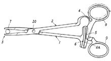
- This example is a case where the working device of Example 1 is configured as a clamping device.
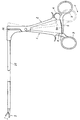
- first member 1 and the second member 2 are pivotally attached to each other so as to move relative to each other, and the front end side portions of the first member 1 and the second member 2 facing each other are attached to the object 7.
- the working unit 3 is used as a clamping unit for clamping, and the working unit 3 is opened / closed by the opening / closing operation of the operating unit 9 provided at the base end portion of each of the first member 1 and the second member 2 facing each other, thereby moving the object 7.
- a work unit configured to hold the object 7 by holding the object 7 while holding the object 7 in the state where the object 7 is held by the work unit 3.
- the clamping force of 3 reaches a predetermined value, even if more force is applied to the operation unit 9, the force further applied to the operation unit 9 is not transmitted to the working unit 3 as the clamping force, and the working unit 3 is constant. In this configuration, the object 7 can be continuously held by the holding force.
- the first member 1 and the second member 2 are formed of an appropriate material, for example, a member made of metal or synthetic resin in the shape of an elongated strip, and the tip side portion of each of the first member 1 and the second member 2 is the object 7.
- An operation portion 9 that is formed in a tapered shape that can be sandwiched, and that opens and closes the working portion 3 that is formed by the distal end side portions of the opposing first member 1 and second member 2 that are formed in the tapered shape at respective base end portions.
- the first member 1 has a contact receiving portion 6, and the second member 2 has a movable factor portion 4 and a movable contact portion 5 that is movable by elastic deformation of the movable factor portion 4.
- the configuration is provided.
- the first member 1 is provided with a contact receiving portion 6 between a pivoting portion 20 that pivotally attaches the first member 1 and the second member 2 and an operation portion 9 provided at the base end portion.
- the contact receiving portion 6 extends along the moving direction of the first member 1 and has a plurality of concave portions arranged in parallel along the length direction of the contact surface 6A. ing.
- the second member 2 has a configuration in which a movable factor portion 4 and a movable abutting portion 5 are provided between the pivoting portion 20 and the operation portion 9 provided at the base end portion.
- the movable contact portion 5 is formed in a shape projecting inwardly at the base end portion of the movable cause portion 4 and at the tip downward.
- the convex portion is provided with a convex portion, and the convex portion is formed in a shape that fits into a concave portion provided on the contact surface 6A of the contact receiving portion 6.
- the first member 1 and the second member 2 move in a direction in which the first member 1 and the second member 2 approach each other.
- the working part 3 constituted by the opposing front end sides of the second member 2 operates in the closing direction.
- the movable factor 4 provided on the second member 2 is not elastically deformed.
- the movable contact portion 5 provided continuously with the movable cause portion 4 is moved along the contact surface 6A of the contact receiving portion 6 of the first member 1 as the first member 1 and the second member 2 move. Specifically, it moves parallel to the contact surface 6A of the contact receiving part 6 without approaching the contact receiving part 6.
- the movable contact unit 5 contacts the contact receiving unit 6.
- the convex portion provided at the tip of the movable contact portion 5 is fitted into the concave portion provided on the contact surface 6A of the contact receiving portion 6, and the movable contact portion 5 is in contact with the contact receiving portion 6. And become locked.
- the applied force is not transmitted to the working portion 3, and the working portion 3 is applied to the object 7.
- the force exerted by the operation unit 3, that is, the clamping force with which the work unit 3 clamps the object 7 does not become larger than the clamping force when the movable contact unit 5 contacts the contact receiving unit 6. Even if a large force is exerted on the object 7 so that the working unit 3 exerts a clamping force of a predetermined value or more, a force larger than the predetermined clamping force is not applied to the object 7, and the clamping operation is performed with the predetermined clamping force.
- the present embodiment is a case where the contact receiving portion 6 is configured differently in the clamping device of the sixth embodiment.
- the interval between the movable contact portion 5 and the contact receiving portion 6 is configured to change depending on the position where the movable contact portion 5 contacts the contact receiving portion 6.
- the contact surface 6 ⁇ / b> A of the contact receiving portion 6 is provided in an inclining state inwardly, and the object 7 to be sandwiched is large and the movable contact portion 5 contacts at an inner position of the contact receiving portion 6.
- the contact interval is widened, and when the object 7 to be sandwiched is small and the movable contact portion 5 contacts at the outer position of the contact receiving portion 6, the contact interval is narrowed and sandwiched.
- the working unit 3 grips the object 7 as the opening of the working unit 3 that sandwiches the object 7 increases.
- the maximum value (peak value) of the clamping force is increased.
- the interval between the movable contact portion 5 and the contact receiving portion 6 can be appropriately set to a predetermined interval for each contact position.
- the contact surface 6A of the contact portion 6 is provided in a downwardly inclined state so that the size of the object 7 to be sandwiched becomes smaller. In other words, when the object 7 is sandwiched, the object 7 is sandwiched. You may comprise so that the maximum value (peak value) of the clamping force with which the operation
- the remaining configuration is the same as that of the sixth embodiment.
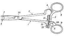
- This example is a case where the clamping device of Example 6 is provided with a lock mechanism that holds the contact state of the movable contact portion 5 with the contact receiving portion 6.
- the force receiving portion 6 of the movable contact portion 5 can be moved without applying force to the operation portion 9. Is held so that the clamping force exerted by the working unit 3 is maintained in a constant state.
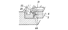
- the lock mechanism of the present embodiment is composed of a locking claw portion 21 provided on the movable contact portion 5 and a concave strip engagement receiving portion 22 provided on the contact receiving portion 6, and the movable contact portion 5 is a contact receiving portion. 6, the latching claw portion 21 provided on the movable contact portion 5 is hooked and locked to the concave latch receiving portion 22 provided on the contact receiving portion 6. The abutting state on the part 6 is maintained.
- FIG. 17 is a diagram showing the unlocked state
- FIG. 18 is a diagram showing the locked state.
- the working part 3 when the working part 3 is actuated and the movable factor part 4 is elastically deformed and the movable contact part 5 approaches and comes into contact with the contact receiving part 6,
- the locking claw portion 21 of the portion 5 gets over the stepped portion 23 of the contact receiving portion 6 and falls into and engages with the concave locking receiving portion 22, and the hook shape of the locking claw portion 21 is obtained by the return elastic force of the movable factor portion 4.
- the movable abutment portion 5 can be engaged with the abutment receiving portion without applying force to the operation portion 9 by engaging the end portion of the grooved engagement with the inner surface of the recess engagement receiving portion 22 in a pressed state and maintaining the hooked engagement state. 6 is held so as to be held in contact with it.
- the remaining configuration is the same as that of the sixth embodiment.
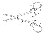
- the contact surface 5A of the movable contact portion 5 that contacts the contact receiving portion 6 is arranged along the moving direction of the second member 2 provided with the movable contact portion 5. This is a case in which the extended configuration is provided and a lock mechanism that holds the contact state of the movable contact portion 5 with the contact receiving portion 6 is also provided.
- the movable contact portion 5 is formed in a shape projecting inwardly in the closing direction of the second member 2, and the contact surface 5A of the movable contact portion 5 is formed in an arc shape.
- the size (diameter, thickness, etc.) of the object 7 held by the working unit 3 changes, the contact position of the movable contact unit 5 that contacts the contact receiving unit 6 varies, but the movable factor 4 The amount of deformation is not changed, and the movable contact portion 5 is formed in a shape that can contact the contact receiving portion 6 with a constant change amount.
- the movable contact portion 5 of the present embodiment has a configuration in which a plurality of recesses are continuously provided along the length direction of the contact surface 5A.
- the contact receiving portion 6 is formed so that the tip thereof is formed in a convex shape and can be fitted into a recess provided on the contact surface 5A of the movable contact portion 5.
- the lock mechanism for holding the contact state between the movable contact portion 5 and the contact receiving portion 6 is constituted by a depression recess 24 provided in the first member 1, specifically, When the movable contact portion 5 comes into contact with the contact receiving portion 6, the movable contact portion 5 falls and engages with the recessed portion 24, and the movable contact portion 5 falls due to the return elastic force of the movable cause portion 4. Engage with the side surface 24A in a pressed state to keep the locked state, and the movable contact portion 5 is kept in contact with the contact receiving portion 6 without applying force to the operation portion 9. is doing.
- the remaining configuration is the same as that of the sixth embodiment.
- both the clamping operation and the expanding operation can be performed, and the movable contact is also applied when the operating resistance of the working unit 3 reaches a predetermined value during the expanding operation. This is a case where the contact portion 5 is in contact with the contact receiving portion 6 and the force applied to the operation portion 9 is not transmitted to the working portion 3 after the contact.
- the movable contact portion 5 is provided with a first contact surface 5B that contacts the contact receiving portion 6 in the clamping operation and a second contact surface 5C that contacts the contact receiving portion 6 in the expanding operation.
- the first abutting surface 5B and the second abutting surface 5C are configured such that a plurality of concave portions are juxtaposed in a connected state along the length direction.
- the contact receiving portion 6 includes a first contact receiving portion 6B that contacts the first contact surface 5B and a second contact receiving portion 6C that contacts the second contact surface 5C.
- 6B and the 2nd contact receiving part 6C are set as the structure provided in the opposing state at the space
- This example is a case where the clamping device of Example 9 is configured as forceps for surgical operation under the microscope.
- each tip side portion is configured to move away from each other, and the working portion 3 is configured to open and close by the separation movement of each tip side portion of the first member 1 and the second member 2.
- a pipe-like extension portion 25 is provided at the distal end side portion of the first member 1, and a working portion 3 is provided at the distal end of the extension portion 25.
- the opening / closing operation is performed by the movement of the wire 26 provided in the section.
- This example is a case where the clamping device of Example 6 is provided with a movable factor deformation preventing mechanism that prevents elastic deformation of the movable factor 4.
- the movable cause portion deformation prevention mechanism is configured such that the lock bar 27 disposed in a erected state acts between the both ends of the movable cause portion 4 formed in a curved shape or an arc shape, and acts as a tension rod. 4 is configured to prevent elastic deformation.
- the lock bar 27 is pivotally attached at one end to a shaft attaching portion 28 provided at one end of the movable factor 4 and the other end is movable.
- the lock bar 27 is locked to the lock portion 29 so as to be detachably locked to the lock portion 29 provided on the other end of the causal portion 4 and is installed between both ends of the movable cause portion 4.
- the elastic deformation of the movable factor portion 4 is locked, and the same effect as the conventional general clamping device, that is, the force applied to the operation portion 9 is not transmitted to the working portion 3 or to the working portion 3.
- the work unit 3 By configuring the work unit 3 to exert a clamping force according to the force applied to the operation unit 9 without reducing the transmission ratio for transmitting the force, and by releasing the lock bar 27 from the locking unit 29
- the elastic factor lock of the movable factor 4 is released.
- the remaining configuration is the same as that of the sixth embodiment.
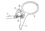
- This example is a case where the configuration of the movable factor part 4 is changed in the clamping device of the sixth example, and specifically, the movable factor part 4 is configured in a hinge form.
- the movable factor portion 4 of the present embodiment includes a hinge portion 45 provided continuously with the movable contact portion 5, and an elastic force that imparts an opening bias to the hinge portion 45.
- the hinge portion 45 is normally held in an expanded state by an elastic body 46 (coil spring in the present embodiment) and an operating resistance is generated in the working portion 3 so that the hinge portion 45 is opened.
- an elastic body 46 coil spring in the present embodiment
- the contact portion 5 is configured to move so as to approach the contact receiving portion 6.
- a coil spring is used as the elastic body 45.
- a torsion spring may be used instead of the coil spring.
- the elastic modulus of the elastic body 45 constituting the movable factor portion 4 specifically, the spring constant of the coil spring or torsion spring having a desired magnitude (set value) is used.
- the degree of deformation of the movable factor portion 4 can be adjusted to a desired degree of deformation.
- the movable factor portion 4 is easily deformed, and the movable contact portion 5 moves and contacts the contact receiving portion 6 with a small operating resistance of the working portion 3. Therefore, the maximum clamping force that can be exerted on the object 7 by the working unit 3 is also reduced, and if the coil spring or the torsion spring having a large spring constant is used, the movable factor 4 is hardly deformed.
- the maximum clamping force that can be exerted on the object can be increased. That is, in this embodiment, the maximum clamping force that can be exerted by the working unit 3 is adjusted by the elastic modulus (coil of the elastic body 45). It is an epoch-making clamping device that can be easily realized by setting the spring constant of the spring or torsion spring.
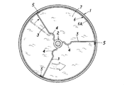
- This example is a case where the working device of Example 1 is configured as a stirring device.
- the first member 1 configured as a container
- the second member 2 configured as a rotating shaft
- the working unit 3 configured as a stirring blade
- the first member 1 (accommodating body) is configured as a bottomed cylindrical accommodating body that accommodates the object 7, and the contact receiving portion 6 is provided on the inner peripheral surface upper part.
- the contact receiving portion 6 is made of a synthetic resin or rubber having elasticity, or is provided with a synthetic resin or rubber having elasticity on the contact surface 6A, and the inner peripheral surface of the first member 1 (container). It is set as the structure around the upper end part.
- the second member 2 (rotating shaft) is configured to be rotatable with respect to the first member 1 (container), and the working portion 3 (stirring blade) is provided on the peripheral surface via the movable factor portion 4.
- the movable contact portion 5 is provided at the tip of the working portion 3 (stirring blade).
- the movable factor portion 4 of the present embodiment is formed of a plate-like member formed in a curved shape or an arc shape, and has one end portion on the circumferential surface of the second member 2 (rotating shaft) so that the opening side faces the rotation direction. It is set as the structure projected toward the direction (radiation direction).
- the working part 3 (stirring blade) is composed of a plate-like member formed in a square shape, and is configured to be connected to the other end of the movable factor part 4 protruding from the second member 2 (rotating shaft).
- the movable contact portion 5 is composed of a plate-like member formed in a square shape, and has a configuration in which the tip is continuously provided at the tip of the working portion 3 (stirring blade) with the direction opposite to the rotation direction.
- the stirring device of the present embodiment when the object 7 accommodated in the first member 1 (container) is agitated, the viscosity of the object 7 is increased by the agitation, and the working resistance of the working unit 3 (agitation blade) is increased.
- the viscosity reaches the predetermined value, in other words, when the viscosity of the object 7 reaches the predetermined value, the movable contact portion 5 moved by the elastic deformation of the movable factor portion 4 is moved to the upper inner periphery of the first member 1 (container).
- the remaining configuration is the same as that of the first embodiment.
- the present embodiment is a case where the working device of the first embodiment is configured as a tightening device, specifically, a binding band as shown in FIG. 30, and the first member 1 and the second member 2 are integrally formed. This is a case where a configuration in which a part of the second member 2 is moved relative to the first member 1 is configured as a continuous configuration.
- the binding band of the present embodiment includes a first member 1 configured as a head portion and a second member 2 configured as a band portion.
- the movable factor portion 4 and the movable factor portion are provided on the first member 1 (head portion).
- 4 is provided with a movable contact portion 5 that is movable by elastic deformation
- the second member 2 (band portion) is provided with a contact receiving portion 6 and an operation portion 9, and the second member 2 (band portion).
- it is set as the structure used as the working part 3 which binds the target object 7.
- the second member 2 (band part) is provided with a serrated engagement part 30 (corresponding to a serration of a general binding band) on the inner surface, and more specifically, the serrated engagement.
- the contact receiving part 6 is provided at a position back to back with the part 30, and the operation part 9 is provided at the tip.
- the claw portion 31 of the first member 1 is connected to the second member 2 until an operating resistance is generated in the working portion 3.
- the second member 2 cannot be moved in the return direction (slack direction) by fitting and engaging with a serrated engagement part 30 provided on the (band part).
- the tip of the second member 2 (band part) is formed.
- the lower end portion of the first member 1 (head portion) connected to the base end portion of the second member 2 (band portion) is pulled, and this first member 1 (head) 32, 33, the movable cause portion 4 is elastically deformed, and the movable contact portion provided on the movable cause portion 4 is elastically deformed as shown in FIGS.
- the portion 5 is movable inward and abuts against a contact receiving portion 6 provided on the second member 2 (band portion).
- the movable contact portion 5 abuts on the contact receiving portion 6, and the contact receiving portion
- the second member 2 (band part) is made immovable by fitting and locking in a recess provided in the contact surface 6A of the Be pulled further applies a force to 9, the second member 2 (band portion) does not move, the tightening force of the working unit 3, which fasten the object 7 is configured to not greater than a predetermined value.
- the binding band is configured such that the object 7 cannot be tightened with a tightening force stronger than a predetermined value. Therefore, when the object 7 is tightened, the object 7 is damaged due to excessive tightening. It is not necessary to perform a careful tightening operation so that the tightening force for tightening the object 7 reaches a predetermined value even if the operation part 9 is pulled by applying force with no effort. It becomes an unprecedented innovative binding band with excellent practicality.
- the remaining configuration is the same as that of the first embodiment.
- Example 1 is configured as an injection device, specifically, as a syringe-like injection device as shown in FIG.
- a present Example consists of the 1st member 1 comprised as an injection cylinder, and the 2nd member 2 comprised as a plunger, provided the movable factor part 4 and the movable contact part 5 in the 1st member 1 (injection cylinder), The contact receiving portion 6 is provided on the second member 2 (plunger).
- the movable factor portion 4 and the movable contact portion 5 are provided in a clamp-like mounting portion 32 that is detachably provided on the first member 1 (injection barrel), and is attached to the first member 1 (injection barrel). More specifically, the movable factor portion 4 is provided in the clamp-shaped attachment portion 32, and the operation factor 9 provided in the second member 2 (plunger) is pushed to the movable factor portion 4 and operated.
- a finger hooking portion 33 for locking a finger is provided, and the movable contact portion 5 is provided on the finger hooking portion 33.
- the finger hooking portion 33 is hooked. The force is increased, and the movable cause part 4 is elastically deformed so that the movable contact part 5 is movable in a direction approaching the contact receiving part 6.
- the first member 1 can be a conventional general syringe, and the first member 1 (syringe) can be provided with a separate movable factor 4 and a movable contact.
- the clamp-like mounting portion 32 provided with the contact portion 5 and the finger hook portion 33 is detachably provided.
- the second member 2 (plunger) itself is the contact receiving portion 6, 37, the movable contact portion 5 is configured to contact the side surface of the second member 2 (plunger) as the contact receiving portion 6, and at the time of contact, the distal end of the movable contact portion 5 is contacted with the contact receiving portion 6.
- the second member 2 (plunger) is difficult to lock.
- this embodiment Describing the application of this embodiment, for example, it can be used as a pump for inflating a balloon of a balloon catheter.
- the balloon in the first member 1 (syringe) is inflated as the balloon is inflated.
- the working resistance of the working part 3 for pushing out air specifically, the tip part (gasket) of the second member 2 (plunger) increases, the balloon inflates to a predetermined size, and the working resistance of the working part 3 reaches a predetermined value.
- the movable contact portion 5 moved by the elastic deformation of the movable cause portion 4 is brought into contact with and locked to the contact receiving portion 6, and the pushing operation of the second member 2 (plunger) can be made impossible.
- the balloon can be an epoch-making infusion device that can expand the blood vessel with an appropriate expansion pressure without looking at the inflated state of the balloon.
- the remaining configuration is the same as that of the first embodiment.
- the working device of Example 1 is configured as a suction device, specifically, a syringe-like suction device as shown in FIG.
- the present embodiment is composed of a first member 1 configured as a syringe barrel and a second member 2 configured as a plunger.
- the first member 1 (syringe barrel) is provided with a contact receiving portion 6, and the second member 2 (plunger).
- the second member 2 Is provided with a movable factor part 4 and a movable contact part 5 which is movable by elastic deformation of the movable factor part 4.
- the first member 1 is a rectangular frame-shaped mounting base provided with a press-fit fitting engagement portion 34 that is fitted and engaged by press-fitting using a syringe barrel of an existing general syringe.
- the portion 35 is detachably provided, the contact receiving portion 6 is provided on the inner surface of each of the left and right vertical frame portions 35A of the mounting base portion 35 in an opposing state, and the contact receiving portion 6 is provided vertically.
- the frame portion 35A has a length in the length direction, and a plurality of concave portions are arranged in parallel in the contact surface 6A along the length direction of the vertical frame portion 35A.
- the second member 2 uses a plunger of an existing general syringe, and a movable contact portion 5 that is movable on a flange 36 at a proximal end portion by elastic deformation of the movable cause portion 4.
- the operation unit 9 for moving the second member 2 (plunger) is detachably provided.
- the movable factor portion 4 is formed in a frame-like body having a triangular shape in plan view, and the flange 36 of the second member 2 (plunger) is formed on the bottom side of the frame-like triangle.
- the left and right oblique sides are elastically deformed, and the elastic deformation causes the distal ends of the oblique sides to move outward (each distal end). The parts move away from each other).
- the movable contact portion 5 has a configuration in which the tip portion is formed in a convex shape, and the tip portion projects outward from the tip portions of the left and right oblique sides of the movable factor portion 4.
- the operation unit 9 is disposed in the inner space of the frame-shaped triangle, and moves along both the left and right oblique sides of the movable factor portion 4 formed in the frame-shaped triangle to spread and expand the left and right oblique sides.
- the portion 37 is provided.
- the second member 2 (plunger) provided movably on the first member 1 (injection cylinder) is pulled in the pulling direction when the operation portion 9 is pulled during suction operation.
- the spread contact portion 37 of the operation portion 9 moves while expanding the movable factor portion 4, and the spread contact portion
- the movable cause portion 4 is elastically deformed by spreading by 37, and the movable contact portion 5 is brought into contact with the contact receiving portion 6 by the elastic deformation of the movable cause portion 4, and the movable contact portion 5 is brought into contact with the contact receiving portion 6.
- the operation unit 9 becomes unable to perform a pulling operation, the suction operation is stopped, and when the movable contact unit 5 is in contact with the contact receiving unit 6, the operation unit 9 is further pulled with a large force. Even if the operation is performed, the force applied to the operation unit 9 is still applied to the second member 2 (plunger) The force is not transmitted as a force for moving, and the suction work disabled state is maintained.
- the movable factor portion 4 can be freely replaced with another movable factor portion 4 having a different elastic modulus, and the movable factor portion 4 can be replaced with a desired elastic modulus so that the working portion 3 can be replaced.
- the maximum suction force that can be exerted on the object 7 can be freely adjusted.
- the remaining configuration is the same as that of the first embodiment.
- the present embodiment is a case where the working device of the first embodiment is configured as a biopsy forceps, and is connected to the first member 1 configured as a main body portion, the second member 2 configured as a slider portion, and the second member 2.
- the working unit 3 is opened and closed by the operation of the wire 39 provided.
- the first member 1 (main body portion) is provided with the contact receiving portion 6 on the peripheral surface, and a guide portion 40 (specifically, a guide groove) for guiding the sliding movement of the second member 2 (slider portion).
- a flexible insertion tube 41 is provided at the distal end portion, and a finger hook locking portion 42 for operating the operation portion 9 is provided at the proximal end portion.
- the second member 2 (slider portion) is provided with a movable factor portion 4, a movable contact portion 5 that is movable by elastic deformation of the movable factor portion 4, and an operation portion 9, and the first member 1 (main body portion) is provided. It is configured to be slidable.
- the operation unit 9 includes a first operation unit 9A and a second operation unit 9B.
- the first operation unit 9A is connected to the second member 2 (slider unit) via the movable factor unit 4.
- the second operation portion 9B is different from the first operation portion 9A and does not include the movable factor portion 4 and the movable contact portion 5.
- the second member 2 (slider portion) is fixed in a non-deformable state.
- the movable factor 4 connected to the first operating unit 9A is elastic.
- the movable contact portion 5 deformed and elastically deformed by the movable cause portion 4 comes into contact with the contact receiving portion 6, and the movable contact portion 5 contacts the contact receiving portion 6.
- the clamping force is configured to exert the working unit 3.
- the remaining configuration is the same as that of the first embodiment.
- the working device of the first embodiment is configured such that the first member 1 and the second member 2 both move in the same direction while maintaining a constant interval. Are both configured to move in the same direction while maintaining a constant interval so that the working unit 3 operates to perform a predetermined work on the object 7.
- the object 7 It is a case where it comprises as a nut as shown in FIG.
- the first member 1 and the second member 2 formed on nuts having the same diameter and the same pitch are arranged in parallel at a predetermined interval, and the first member 1 in this juxtaposed state is arranged.
- the second member 2 is connected and integrated by a movable factor 4 that can be elastically deformed.
- the bottom surface or top surface of the opposing first member 1 and the bottom surface or top surface of the second member 2 that are arranged side by side are the movable contact portion 5, the other is the contact receiving portion 6, and the target
- the working portion 3 is a surface that contacts the object 7 and presses the object 7 by tightening.
- the abutting side is the first member 1
- the upper surface or the bottom surface of the first member 1 facing the second member 2 is the abutting receiving portion 6
- the upper surface or the bottom surface of the abutting receiving portion 6 is the opposite surface.
- the bottom surface or top surface is the working unit 3.
- the second member 2 is the one located on the opposite side of the moving direction of the moving direction, and the upper surface or the bottom surface of the second member 2 facing the first member 1 is the movable contact portion 5.
- the movable factor part 4 which connects the 1st member 1 and the 2nd member 2 is set as the structure formed helically as shown in FIG. 46, and the movable factor part connection part 43 which provided the one end part in the 1st member 1 The other end is connected to the movable factor connecting part 43 provided on the second member 2 and is constructed between the first member 1 and the second member.
- a force is applied to one of the first member 1 and the second member 2 that are movably screwed to the bolt 44, specifically, to the second member 2.
- the force applied to the second member 2 is also transmitted to the first member 1 via the movable factor portion 4, and the first member 1 and the second member 2 are separated by a certain distance by the movable factor portion 4.
- the working part 3 (the upper surface or the bottom surface of the first member 1) is actuated by the movement of the first member 1 and the second member 2, and the actuating resistance is applied to the actuated working part 3.
- the contact receiving part 6 provided on the first member 1 and the second part 2 are moved along with the movement of the first member 1 and the second member 2.
- the movable abutting portion 5 provided on the member 2 moves in the same direction while maintaining a constant interval like the first member 1 and the second member 2. It has a configuration that.
- the movable factor portion 4 connecting the first member 1 and the second member 2 is elastically deformed.
- the movable contact portion 5 is configured to move in a direction in which the movable contact portion 5 approaches the contact receiving portion 6 by elastic deformation. Specifically, the movement stops when the working portion 3 of the first member 1 contacts the object 7 or When the moving speed is lower than that of the second member 2 and the moving speed between the movable contact portion 5 and the contact receiving portion 6 is different, the movable factor portion 4 is deformed and the movable contact portion 5 and the contact receiving portion 6 are deformed. And the movable contact portion 5 approaches the contact receiving portion 6.
- the deformation amount of the movable factor part 4 increases, the distance between the movable contact part 5 and the contact receiving part 6 is further narrowed, and approaches each other.
- the movable contact portion 5 contacts the contact receiving portion 6.
- the second member 2 Even if a force is further applied, the second member 2 is not screwed, so that the force applied to the second member 2 is not transmitted to the first member 1, specifically, the working unit 3.
- the second member 2 cannot be screwed in the tightening direction because the movable contact portion 5 of the second member 2 contacts the contact receiving portion 6 of the first member 1, and this second member The force applied to the second member 2 is not transmitted to the first member 1 due to the inability to screw 2 and the tightening (pressing) operation on the object 7 of the working portion 3 of the first member 1 is stopped. .
- the diameter of the movable cause part 4 formed in a spiral shape can be adjusted, or the movable cause parts 4 having different elastic moduli can be connected to each other.
- the maximum tightening force (pressing force) that can be exhibited can be freely adjusted.
- the present invention is an epoch-making working apparatus that can be used for various purposes by changing the form as the above-described embodiment, and the present invention is not limited to Embodiments 1 to 19. Rather, the specific configuration of each component can be designed as appropriate.
Landscapes
- Engineering & Computer Science (AREA)
- Mechanical Engineering (AREA)
- General Engineering & Computer Science (AREA)
- Health & Medical Sciences (AREA)
- Oral & Maxillofacial Surgery (AREA)
- Manipulator (AREA)
- Gripping Jigs, Holding Jigs, And Positioning Jigs (AREA)
- Clamps And Clips (AREA)
- Flexible Shafts (AREA)
- Push-Button Switches (AREA)
Priority Applications (2)
| Application Number | Priority Date | Filing Date | Title |
|---|---|---|---|
| EP14814443.9A EP3012070B1 (de) | 2013-06-21 | 2014-03-25 | Arbeitsvorrichtung |
| US14/898,314 US20160136788A1 (en) | 2013-06-21 | 2014-03-25 | Work apparatus |
Applications Claiming Priority (2)
| Application Number | Priority Date | Filing Date | Title |
|---|---|---|---|
| JP2013130960A JP5629357B1 (ja) | 2013-06-21 | 2013-06-21 | 作業装置 |
| JP2013-130960 | 2013-06-21 |
Publications (1)
| Publication Number | Publication Date |
|---|---|
| WO2014203578A1 true WO2014203578A1 (ja) | 2014-12-24 |
Family
ID=52104322
Family Applications (1)
| Application Number | Title | Priority Date | Filing Date |
|---|---|---|---|
| PCT/JP2014/058199 Ceased WO2014203578A1 (ja) | 2013-06-21 | 2014-03-25 | 作業装置 |
Country Status (4)
| Country | Link |
|---|---|
| US (1) | US20160136788A1 (de) |
| EP (1) | EP3012070B1 (de) |
| JP (1) | JP5629357B1 (de) |
| WO (1) | WO2014203578A1 (de) |
Families Citing this family (3)
| Publication number | Priority date | Publication date | Assignee | Title |
|---|---|---|---|---|
| US11478903B2 (en) * | 2017-07-10 | 2022-10-25 | Nigel Buchanan | Pliers |
| US12220145B2 (en) | 2021-03-29 | 2025-02-11 | Medtronic Vascular, Inc. | Debulking catheter |
| WO2022208243A1 (en) * | 2021-03-29 | 2022-10-06 | Medtronic Vascular, Inc. | Debulking catheter |
Citations (5)
| Publication number | Priority date | Publication date | Assignee | Title |
|---|---|---|---|---|
| JPH0583414U (ja) * | 1992-04-22 | 1993-11-12 | 大和化成工業株式会社 | ベルトクランプ |
| JPH10277960A (ja) * | 1997-02-17 | 1998-10-20 | Bessey & Sohn Gmbh & Co | チャック装置 |
| JP2005187073A (ja) * | 2003-12-05 | 2005-07-14 | Panduit Corp | 陥凹面を設けたストラップ緊結用バックル |
| WO2012053123A1 (ja) * | 2010-10-19 | 2012-04-26 | ナシモト工業 株式会社 | 開閉作業具 |
| JP3177360U (ja) * | 2012-04-26 | 2012-08-02 | イーグルクランプ株式会社 | ネジ式クランプ |
Family Cites Families (17)
| Publication number | Priority date | Publication date | Assignee | Title |
|---|---|---|---|---|
| US409295A (en) * | 1889-08-20 | George a | ||
| SE460745B (sv) * | 1988-02-29 | 1989-11-13 | Fast Industriprodukter Hb | Klaemma |
| US5370659A (en) * | 1992-04-09 | 1994-12-06 | Olympus Optical Co., Ltd. | Grasping forceps for medical treatment |
| US5304203A (en) * | 1992-10-20 | 1994-04-19 | Numed Technologies, Inc. | Tissue extracting forceps for laparoscopic surgery |
| US5827323A (en) * | 1993-07-21 | 1998-10-27 | Charles H. Klieman | Surgical instrument for endoscopic and general surgery |
| DE4411099C2 (de) * | 1994-03-30 | 1998-07-30 | Wolf Gmbh Richard | Chirurgisches Instrument |
| US5603723A (en) * | 1995-01-11 | 1997-02-18 | United States Surgical Corporation | Surgical instrument configured to be disassembled for cleaning |
| DE19510962C2 (de) * | 1995-03-25 | 1998-02-05 | Winter & Ibe Olympus | Medizinisch-endoskopisches Gerät mit superelastischem Element |
| US5893307A (en) * | 1997-04-25 | 1999-04-13 | Tao; Liang-Che | Pliers with biasing element |
| DE19731453C2 (de) * | 1997-07-22 | 1999-07-22 | Storz Karl Gmbh & Co | Vorrichtung zum Begrenzen der Kraftübertragung an chirurgischen Instrumenten |
| US5938685A (en) * | 1997-09-05 | 1999-08-17 | Boston Scientific Corporation | Locking handle for surgical instruments |
| US6139563A (en) * | 1997-09-25 | 2000-10-31 | Allegiance Corporation | Surgical device with malleable shaft |
| FR2868938B1 (fr) * | 2004-04-16 | 2006-07-07 | Memometal Technologies Soc Par | Pince permettant la mise en place d'une agrafe d'osteosynthese de type superelastique |
| US7727256B2 (en) * | 2004-09-24 | 2010-06-01 | Arthrex, Inc. | Grasper assembly |
| USD548836S1 (en) * | 2005-06-08 | 2007-08-14 | Karl Storz Gmbh & Co. Kg | Medical probe |
| CN102216644B (zh) * | 2008-11-20 | 2014-02-05 | 奥依列斯工业株式会社 | 旋转式阻尼器 |
| US10172672B2 (en) * | 2016-01-11 | 2019-01-08 | Covidien Lp | Jaw force control for electrosurgical forceps |
-
2013
- 2013-06-21 JP JP2013130960A patent/JP5629357B1/ja not_active Expired - Fee Related
-
2014
- 2014-03-25 US US14/898,314 patent/US20160136788A1/en not_active Abandoned
- 2014-03-25 WO PCT/JP2014/058199 patent/WO2014203578A1/ja not_active Ceased
- 2014-03-25 EP EP14814443.9A patent/EP3012070B1/de active Active
Patent Citations (6)
| Publication number | Priority date | Publication date | Assignee | Title |
|---|---|---|---|---|
| JPH0583414U (ja) * | 1992-04-22 | 1993-11-12 | 大和化成工業株式会社 | ベルトクランプ |
| JPH10277960A (ja) * | 1997-02-17 | 1998-10-20 | Bessey & Sohn Gmbh & Co | チャック装置 |
| JP2005187073A (ja) * | 2003-12-05 | 2005-07-14 | Panduit Corp | 陥凹面を設けたストラップ緊結用バックル |
| WO2012053123A1 (ja) * | 2010-10-19 | 2012-04-26 | ナシモト工業 株式会社 | 開閉作業具 |
| JP4995961B2 (ja) | 2010-10-19 | 2012-08-08 | ナシモト工業株式会社 | 開閉作業具 |
| JP3177360U (ja) * | 2012-04-26 | 2012-08-02 | イーグルクランプ株式会社 | ネジ式クランプ |
Also Published As
| Publication number | Publication date |
|---|---|
| EP3012070B1 (de) | 2019-04-24 |
| EP3012070A1 (de) | 2016-04-27 |
| JP2015003369A (ja) | 2015-01-08 |
| JP5629357B1 (ja) | 2014-11-19 |
| EP3012070A4 (de) | 2017-03-15 |
| US20160136788A1 (en) | 2016-05-19 |
Similar Documents
| Publication | Publication Date | Title |
|---|---|---|
| US6367787B1 (en) | Hand clamp | |
| EP2025472A2 (de) | Ratschenschlüssel mit offenem Maul | |
| US20150033514A1 (en) | Self-adjusting bar clamp | |
| JP5629357B1 (ja) | 作業装置 | |
| EP3251797B1 (de) | Zange | |
| GB2436705A (en) | A jaw for a bar clamp | |
| US7090209B1 (en) | Adjustable clamp and method of using an adjustable clamp | |
| US8607671B2 (en) | Wrench with trigger | |
| US7389978B2 (en) | Adjustable clamp | |
| US9270072B2 (en) | Dieless crimping tool | |
| US10772620B2 (en) | Adjustable motion limiter for a minimally invasive surgical device | |
| US9088144B2 (en) | Armor clamping and cutting tool | |
| US10272545B2 (en) | Locking pliers | |
| US20240166389A1 (en) | Cable tie tensioning and cut-off tool | |
| WO2014097494A1 (ja) | 開閉作業具 | |
| CA2851459A1 (en) | Adjustable ratcheting socket tool | |
| CN100408273C (zh) | 电动镊子 | |
| JP5438157B2 (ja) | 開閉作業具 | |
| KR101868577B1 (ko) | 클램프 | |
| MX2013003031A (es) | Herramienta de torsion de cabezal de compresion. | |
| TWI891190B (zh) | 快速夾頭 | |
| JP5526167B2 (ja) | 開閉作業具 | |
| JP5498519B2 (ja) | 開閉作業具 | |
| GB2635275A (en) | Handheld clamping device | |
| AU2024361636A1 (en) | Handheld clamping device |
Legal Events
| Date | Code | Title | Description |
|---|---|---|---|
| 121 | Ep: the epo has been informed by wipo that ep was designated in this application |
Ref document number: 14814443 Country of ref document: EP Kind code of ref document: A1 |
|
| WWE | Wipo information: entry into national phase |
Ref document number: 14898314 Country of ref document: US |
|
| NENP | Non-entry into the national phase |
Ref country code: DE |
|
| WWE | Wipo information: entry into national phase |
Ref document number: 2014814443 Country of ref document: EP |