WO2014203591A1 - Procédé de fabrication et dispositif de fabrication de combustible solide - Google Patents
Procédé de fabrication et dispositif de fabrication de combustible solide Download PDFInfo
- Publication number
- WO2014203591A1 WO2014203591A1 PCT/JP2014/059767 JP2014059767W WO2014203591A1 WO 2014203591 A1 WO2014203591 A1 WO 2014203591A1 JP 2014059767 W JP2014059767 W JP 2014059767W WO 2014203591 A1 WO2014203591 A1 WO 2014203591A1
- Authority
- WO
- WIPO (PCT)
- Prior art keywords
- carrier gas
- porous coal
- amount
- slurry
- solid fuel
- Prior art date
- Legal status (The legal status is an assumption and is not a legal conclusion. Google has not performed a legal analysis and makes no representation as to the accuracy of the status listed.)
- Ceased
Links
Images
Classifications
-
- C—CHEMISTRY; METALLURGY
- C10—PETROLEUM, GAS OR COKE INDUSTRIES; TECHNICAL GASES CONTAINING CARBON MONOXIDE; FUELS; LUBRICANTS; PEAT
- C10L—FUELS NOT OTHERWISE PROVIDED FOR; NATURAL GAS; SYNTHETIC NATURAL GAS OBTAINED BY PROCESSES NOT COVERED BY SUBCLASSES C10G OR C10K; LIQUIFIED PETROLEUM GAS; USE OF ADDITIVES TO FUELS OR FIRES; FIRE-LIGHTERS
- C10L9/00—Treating solid fuels to improve their combustion
- C10L9/10—Treating solid fuels to improve their combustion by using additives
-
- C—CHEMISTRY; METALLURGY
- C10—PETROLEUM, GAS OR COKE INDUSTRIES; TECHNICAL GASES CONTAINING CARBON MONOXIDE; FUELS; LUBRICANTS; PEAT
- C10L—FUELS NOT OTHERWISE PROVIDED FOR; NATURAL GAS; SYNTHETIC NATURAL GAS OBTAINED BY PROCESSES NOT COVERED BY SUBCLASSES C10G OR C10K; LIQUIFIED PETROLEUM GAS; USE OF ADDITIVES TO FUELS OR FIRES; FIRE-LIGHTERS
- C10L5/00—Solid fuels
-
- C—CHEMISTRY; METALLURGY
- C10—PETROLEUM, GAS OR COKE INDUSTRIES; TECHNICAL GASES CONTAINING CARBON MONOXIDE; FUELS; LUBRICANTS; PEAT
- C10L—FUELS NOT OTHERWISE PROVIDED FOR; NATURAL GAS; SYNTHETIC NATURAL GAS OBTAINED BY PROCESSES NOT COVERED BY SUBCLASSES C10G OR C10K; LIQUIFIED PETROLEUM GAS; USE OF ADDITIVES TO FUELS OR FIRES; FIRE-LIGHTERS
- C10L9/00—Treating solid fuels to improve their combustion
-
- C—CHEMISTRY; METALLURGY
- C10—PETROLEUM, GAS OR COKE INDUSTRIES; TECHNICAL GASES CONTAINING CARBON MONOXIDE; FUELS; LUBRICANTS; PEAT
- C10L—FUELS NOT OTHERWISE PROVIDED FOR; NATURAL GAS; SYNTHETIC NATURAL GAS OBTAINED BY PROCESSES NOT COVERED BY SUBCLASSES C10G OR C10K; LIQUIFIED PETROLEUM GAS; USE OF ADDITIVES TO FUELS OR FIRES; FIRE-LIGHTERS
- C10L9/00—Treating solid fuels to improve their combustion
- C10L9/02—Treating solid fuels to improve their combustion by chemical means
-
- C—CHEMISTRY; METALLURGY
- C10—PETROLEUM, GAS OR COKE INDUSTRIES; TECHNICAL GASES CONTAINING CARBON MONOXIDE; FUELS; LUBRICANTS; PEAT
- C10L—FUELS NOT OTHERWISE PROVIDED FOR; NATURAL GAS; SYNTHETIC NATURAL GAS OBTAINED BY PROCESSES NOT COVERED BY SUBCLASSES C10G OR C10K; LIQUIFIED PETROLEUM GAS; USE OF ADDITIVES TO FUELS OR FIRES; FIRE-LIGHTERS
- C10L9/00—Treating solid fuels to improve their combustion
- C10L9/08—Treating solid fuels to improve their combustion by heat treatments, e.g. calcining
-
- F—MECHANICAL ENGINEERING; LIGHTING; HEATING; WEAPONS; BLASTING
- F26—DRYING
- F26B—DRYING SOLID MATERIALS OR OBJECTS BY REMOVING LIQUID THEREFROM
- F26B11/00—Machines or apparatus for drying solid materials or objects with movement which is non-progressive
- F26B11/02—Machines or apparatus for drying solid materials or objects with movement which is non-progressive in moving drums or other mainly-closed receptacles
- F26B11/04—Machines or apparatus for drying solid materials or objects with movement which is non-progressive in moving drums or other mainly-closed receptacles rotating about a horizontal or slightly-inclined axis
- F26B11/0463—Machines or apparatus for drying solid materials or objects with movement which is non-progressive in moving drums or other mainly-closed receptacles rotating about a horizontal or slightly-inclined axis having internal elements, e.g. which are being moved or rotated by means other than the rotating drum wall
- F26B11/0477—Machines or apparatus for drying solid materials or objects with movement which is non-progressive in moving drums or other mainly-closed receptacles rotating about a horizontal or slightly-inclined axis having internal elements, e.g. which are being moved or rotated by means other than the rotating drum wall for mixing, stirring or conveying the materials to be dried, e.g. mounted to the wall, rotating with the drum
-
- F—MECHANICAL ENGINEERING; LIGHTING; HEATING; WEAPONS; BLASTING
- F26—DRYING
- F26B—DRYING SOLID MATERIALS OR OBJECTS BY REMOVING LIQUID THEREFROM
- F26B21/00—Arrangements for supplying or controlling air or other gases for drying solid materials or objects
- F26B21/20—Circulating air or gases in closed cycles, e.g. wholly within the drying enclosure
- F26B21/25—Circulating air or gases in closed cycles, e.g. wholly within the drying enclosure partly outside the drying enclosure
-
- F—MECHANICAL ENGINEERING; LIGHTING; HEATING; WEAPONS; BLASTING
- F26—DRYING
- F26B—DRYING SOLID MATERIALS OR OBJECTS BY REMOVING LIQUID THEREFROM
- F26B21/00—Arrangements for supplying or controlling air or other gases for drying solid materials or objects
- F26B21/30—Controlling, e.g. regulating, parameters of gas supply
- F26B21/33—Humidity
-
- F—MECHANICAL ENGINEERING; LIGHTING; HEATING; WEAPONS; BLASTING
- F26—DRYING
- F26B—DRYING SOLID MATERIALS OR OBJECTS BY REMOVING LIQUID THEREFROM
- F26B23/00—Heating arrangements
- F26B23/02—Heating arrangements using combustion heating
-
- C—CHEMISTRY; METALLURGY
- C10—PETROLEUM, GAS OR COKE INDUSTRIES; TECHNICAL GASES CONTAINING CARBON MONOXIDE; FUELS; LUBRICANTS; PEAT
- C10L—FUELS NOT OTHERWISE PROVIDED FOR; NATURAL GAS; SYNTHETIC NATURAL GAS OBTAINED BY PROCESSES NOT COVERED BY SUBCLASSES C10G OR C10K; LIQUIFIED PETROLEUM GAS; USE OF ADDITIVES TO FUELS OR FIRES; FIRE-LIGHTERS
- C10L2290/00—Fuel preparation or upgrading, processes or apparatus therefore, comprising specific process steps or apparatus units
- C10L2290/06—Heat exchange, direct or indirect
-
- C—CHEMISTRY; METALLURGY
- C10—PETROLEUM, GAS OR COKE INDUSTRIES; TECHNICAL GASES CONTAINING CARBON MONOXIDE; FUELS; LUBRICANTS; PEAT
- C10L—FUELS NOT OTHERWISE PROVIDED FOR; NATURAL GAS; SYNTHETIC NATURAL GAS OBTAINED BY PROCESSES NOT COVERED BY SUBCLASSES C10G OR C10K; LIQUIFIED PETROLEUM GAS; USE OF ADDITIVES TO FUELS OR FIRES; FIRE-LIGHTERS
- C10L2290/00—Fuel preparation or upgrading, processes or apparatus therefore, comprising specific process steps or apparatus units
- C10L2290/08—Drying or removing water
-
- C—CHEMISTRY; METALLURGY
- C10—PETROLEUM, GAS OR COKE INDUSTRIES; TECHNICAL GASES CONTAINING CARBON MONOXIDE; FUELS; LUBRICANTS; PEAT
- C10L—FUELS NOT OTHERWISE PROVIDED FOR; NATURAL GAS; SYNTHETIC NATURAL GAS OBTAINED BY PROCESSES NOT COVERED BY SUBCLASSES C10G OR C10K; LIQUIFIED PETROLEUM GAS; USE OF ADDITIVES TO FUELS OR FIRES; FIRE-LIGHTERS
- C10L2290/00—Fuel preparation or upgrading, processes or apparatus therefore, comprising specific process steps or apparatus units
- C10L2290/24—Mixing, stirring of fuel components
-
- C—CHEMISTRY; METALLURGY
- C10—PETROLEUM, GAS OR COKE INDUSTRIES; TECHNICAL GASES CONTAINING CARBON MONOXIDE; FUELS; LUBRICANTS; PEAT
- C10L—FUELS NOT OTHERWISE PROVIDED FOR; NATURAL GAS; SYNTHETIC NATURAL GAS OBTAINED BY PROCESSES NOT COVERED BY SUBCLASSES C10G OR C10K; LIQUIFIED PETROLEUM GAS; USE OF ADDITIVES TO FUELS OR FIRES; FIRE-LIGHTERS
- C10L2290/00—Fuel preparation or upgrading, processes or apparatus therefore, comprising specific process steps or apparatus units
- C10L2290/58—Control or regulation of the fuel preparation of upgrading process
Definitions
- the present invention relates to a method and an apparatus for producing a solid fuel using porous coal as a raw material.
- the present invention relates to a solid fuel manufacturing method and a manufacturing apparatus characterized by stable operation in a drying process in which a carrier gas is supplied and dried while heating and conveying separated modified porous coal.
- porous coal (raw coal) is pulverized in a pulverization step, and then mixed with a mixed oil containing heavy oil and solvent oil in a mixing step to obtain a raw material slurry.
- the raw material slurry is preheated and then heated in an evaporation step to dehydrate the porous coal and impregnate the mixed oil into the pores to obtain a dehydrated slurry.
- the dehydrated slurry is separated into the modified porous coal and the mixed oil in the solid-liquid separation step, and then only the modified porous coal is dried in the drying step.
- the modified porous charcoal is conveyed and heated in a heating rotary dryer, and dried by flowing the carrier gas.
- solid fuel is obtained by cooling and shape
- the mixed oil recovered in the solid-liquid separation process and the drying process is recycled to the mixing process and reused. Further, the carrier gas recovered in the drying step is recirculated into the dryer and reused.
- the transport amount of porous coal may fluctuate due to fluctuations in operating conditions in each process. For this reason, in the drying process, when the transport amount of the modified porous coal rapidly increases, the amount of evaporated oil may increase and the internal pressure may increase. As a result, the sealing performance (sealing performance) is impaired and gas may leak out.
- the main component of the carrier gas is nitrogen, but since it contains solids in addition to solvent oil and moisture, the running cost increases due to loss of solvent oil, dust is scattered, and a strange odor is generated. There is concern about adverse effects on the surrounding environment.
- the transport amount of the modified porous coal when the transport amount of the modified porous coal is suddenly reduced in the drying process, the amount of evaporated oil may be reduced, the internal pressure may be reduced, and negative pressure may be obtained.
- the ambient atmosphere penetrates into the interior, and as a result of the increase in the oxygen concentration inside, there is a risk that the stability of the modified porous coal at a high temperature is impaired.
- an object of the present invention is to enable the drying process to be performed in a stable state regardless of the increase or decrease in the transport amount of the porous coal.
- the present invention provides: A mixing step of mixing a porous charcoal with a mixed oil containing a solvent oil and a heavy component to obtain a raw slurry; Evaporating step of heating the raw slurry to advance dehydration of the porous coal, and impregnating the mixed oil into the pores of the porous coal to obtain a dehydrated slurry; A solid-liquid separation step of separating the modified porous charcoal and the mixed oil from the dewatered slurry; A drying step of drying by supplying a carrier gas while heating and conveying the modified porous charcoal; With The target value of the circulating amount of the carrier gas in the drying step and the target value of the carrier gas pressure are set, and the control output is calculated based on the deviation between each target value and the corresponding measured value.
- a solid fuel manufacturing method is provided that adjusts the amount of carrier gas supplied based on the smaller value of the control outputs.
- the supply amount of the carrier gas is adjusted based on the smaller one of the control outputs calculated based on the circulation amount and the pressure of the carrier gas, a significant change occurs.
- the pressure of the carrier gas in the drying process can be stabilized.
- the target values are preferably determined based on the supply amount of the modified porous coal to be dried in the drying step and the amount of oil contained in the modified porous coal that has undergone the drying step.
- the target values are preferably determined so that the pressure of the carrier gas in the drying process is within a preset range.
- the present invention provides: A mixing tank for obtaining a raw material slurry by mixing porous charcoal with a mixed oil containing a solvent oil and a heavy oil; An evaporator that heats the raw slurry to advance dehydration of the porous coal and impregnates the mixed oil into the pores of the porous coal to obtain a dehydrated slurry; A centrifuge for separating the modified porous charcoal and the mixed oil from the dewatered slurry; A dryer for drying by supplying a carrier gas while heating and conveying the modified porous charcoal; In the dryer, a target value for the circulation amount of the carrier gas and a target value for the pressure of the carrier gas are set, and a control output is calculated based on the deviation between each target value and the corresponding measured value. A control unit that adjusts the supply amount of the carrier gas based on the smaller value of the control outputs, An apparatus for producing a solid fuel comprising:
- the control unit determines the target values based on the supply amount of the modified porous coal to be dried by the dryer and the amount of oil contained in the modified porous coal that has passed through the dryer. preferable.
- the control unit preferably determines the target values so that the pressure of the carrier gas in the drying process is within a preset range.
- the supply amount of the carrier gas is adjusted based on the smaller one of the control outputs calculated based on the circulation amount and the pressure of the carrier gas. For this reason, it is possible to contribute to the stability of the operability in the drying process by quickly leading the circulation amount and pressure of the carrier gas to a stable state.
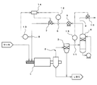
- FIG. 1 schematically shows a part of a modified lignite production apparatus (an example of a solid fuel production apparatus) according to this embodiment.
- this modified lignite production apparatus executes a mixing step in a mixing tank, performs an evaporation step in an evaporator, and executes a solid-liquid separation step in a decanter centrifuge. Moreover, a drying process is performed with the dryer 1 and a modified lignite is obtained.
- the carrier gas is supplied and dried while heating and transporting the modified porous coal.
- nitrogen (N 2 ) as a carrier gas prevents ignition of the modified porous coal.
- the modified porous coal supplied into the dryer 1 is assumed to contain 30 to 40% oil.
- the dryer 1 is provided with a heater (not shown), and an indirect heating type in which the temperature of the internal carrier gas is adjusted to about 200 ° C. is used.
- the modified porous charcoal is transported in the dryer 1 by a screw conveyor.
- the rotating shaft of the screw conveyor is cylindrical, and a plurality of small diameter holes are formed on the outer peripheral surface.
- the carrier gas can be newly supplied into the dryer 1 via the rotating shaft.
- a circulation path 2 for collecting the carrier gas and supplying it again into the dryer 1 is connected to the dryer 1.
- a dust collector 3, a spray tower 4, a blower 5, a flow rate detection sensor 6, a first flow rate adjustment valve 7, and a first pressure detection sensor 8 are provided in order from the outlet side of the dryer 1.
- An exhaust pipe 9 is connected to the pipe from the spray tower 4 to the blower 5, and a second flow rate adjusting valve 10 is provided there. Further, the pressure in the middle of the pipe connecting the dust collector 3 and the spray tower 4 is detected by the second pressure detection sensor 11.
- the detection signal from the flow detection sensor 6 is input to an FIC (Flow Indication Controller) 12.
- a detection signal from the first pressure detection sensor 8 is input to a first PIC (Pressure (Indication Controller) 13.
- the FIC 12 and the PIC 13 calculate a control output value according to (Equation 1).
- the control output values calculated by the FIC 12 and the PIC 13 are compared by the LS circuit 14 (Low Select circuit), and the opening degree of the first flow rate adjusting valve 7 is adjusted based on the lower value.
- the pressure of the carrier gas in the circulation path 2 can be within a predetermined range (for example, 1 to 2 kPa. However, this value depends on the seal design and operating conditions of the conveyor, the dryer 1, etc.
- the opening degree of the first flow rate adjusting valve 7 is adjusted so as to be maintained.
- a detection signal from the second pressure detection sensor 11 is input to the second PIC 15. Based on this input signal, the second PIC 15 adjusts the opening of the second flow rate adjusting valve 10 as described later, thereby suppressing an increase in pressure in the circulation path 2.
- the dust collector 3 is for recovering the dust of the modified porous coal contained in the carrier gas discharged from the dryer 1. From the dryer 1 or the dust collector 3, modified brown coal (UBC: Upgraded Brown Coal) is discharged.
- the spray tower 4 is for condensing and separating the mixed oil from the carrier gas that has passed through the dust collector 3.
- the blower 5 is for forming a carrier gas flow from the circulation path 2 to the dryer 1.
- a modified lignite (an example of a solid fuel) is obtained by a mixing step, an evaporation step, a solid-liquid separation step, and a drying step.
- the mixing step the porous charcoal is mixed with the mixed oil containing the solvent oil and the heavy component in a mixing tank to obtain a raw material slurry.
- the evaporation step the raw material slurry obtained in the mixing step is heated with an evaporator to advance dehydration of the porous coal.
- the mixed oil is impregnated into the pores of the porous coal to obtain a dehydrated slurry.
- the modified porous charcoal and the mixed oil are separated from the dehydrated slurry by a decanter centrifuge.
- the drying step the dryer 1 is supplied with a carrier gas while drying and transporting the modified porous coal obtained in the solid-liquid separation step in the dryer 1 to obtain modified lignite.
- the target of the circulation amount of the carrier gas is determined based on the supply amount of the porous coal supplied into the dryer 1 and the amount of oil contained in the porous coal on the outlet side of the decanter centrifuge.
- a value and a target value of the pressure of the carrier gas at the inlet of the dryer 1 are set.
- the carrier is set so that the pressure of the carrier gas in the dryer 1 is within a preset pressure range (set pressure range) with respect to the supply amount of the porous coal and the amount of oil contained therein.
- a target value for the amount of gas circulation and a target value for pressure are set. These target values may be set in advance through experiments or the like.
- Equation 1 (hereinafter referred to as the following equation).
- the value of this control output is referred to as a first control output value).
- the value of the control output is similarly calculated according to (Equation 1). (Hereinafter, this control output value is referred to as a second control output value).
- the calculated control output value is compared by Low Select control, and the opening degree of the 1st flow regulating valve 7 is adjusted according to the smaller value.
- the control output value is calculated based on the flow rate detected by the flow rate detection sensor 6 and the target value, and the first flow rate adjustment valve 7 The opening is adjusted.
- the flow rate of the carrier gas detected by the flow rate detection sensor 6 when the amount of the oil that evaporates inside increases due to the rapid increase in the amount of the modified porous coal carried into the dryer 1. Does not vary so much, but the pressure detected by the first pressure detection sensor 8 increases.
- the second control output value calculated in (Equation 1) is smaller than the first control output value. Therefore, the opening degree of the first flow rate adjusting valve 7 is adjusted based on the second control output value. Thereby, the pressure in the dryer 1 can be maintained within a desired range and stabilized by suppressing the flow rate of the carrier gas to be refluxed into the dryer 1.
- the control output value is calculated according to the above (Equation 1).
- the opening degree of the 2nd flow regulating valve 10 is adjusted based on the calculated control output value.
- the discharged carrier gas is guided to an unillustrated off-gas processing apparatus.
- the carrier gas introduced to the off-gas treatment apparatus is reused by being supplied to the dryer 1 as appropriate.
- the control output value is calculated according to the above (Equation 1). And the opening degree of the 2nd flow regulating valve 10 is adjusted based on the calculated control output value. In this case, since the detected pressure is greatly reduced, the second flow rate adjustment valve 10 is fully closed, and the carrier gas is not discharged to the outside.
- the opening degree of the first flow rate adjusting valve 7 is adjusted accordingly.
- the smaller value of the first control output value and the second control output value is used by the Low / Select control. Therefore, the opening degree of the first flow rate adjusting valve 7 does not change abruptly, and the pressure of the carrier gas in the dryer 1 can be stabilized.
- the opening degree of the first flow rate adjusting valve 7 is adjusted by PID control (Proportional Integral Derivative Controller), but may be performed by other feedback control.
- PID control Proportional Integral Derivative Controller
- the detection signal from the flow rate detection sensor 6 is processed by the FIC 12
- the detection signal from the first pressure detection sensor 8 is processed by the first PIC 13
- the detection signal from the second pressure detection sensor 11 is changed to the first signal.
- the processing is performed by the 2PIC15, these may be collectively controlled by one control unit (microcomputer), or the FIC12 and the first PIC13 may be controlled by one control unit (microcomputer). Good.
Landscapes
- Engineering & Computer Science (AREA)
- Chemical & Material Sciences (AREA)
- Mechanical Engineering (AREA)
- General Engineering & Computer Science (AREA)
- Combustion & Propulsion (AREA)
- Oil, Petroleum & Natural Gas (AREA)
- Organic Chemistry (AREA)
- Chemical Kinetics & Catalysis (AREA)
- General Chemical & Material Sciences (AREA)
- Life Sciences & Earth Sciences (AREA)
- Sustainable Development (AREA)
- Thermal Sciences (AREA)
- Physics & Mathematics (AREA)
- Solid Fuels And Fuel-Associated Substances (AREA)
Abstract
Priority Applications (5)
| Application Number | Priority Date | Filing Date | Title |
|---|---|---|---|
| US14/892,151 US20160122675A1 (en) | 2013-06-19 | 2014-04-02 | Solid fuel manufacturing method and manufacturing device |
| AU2014282553A AU2014282553B2 (en) | 2013-06-19 | 2014-04-02 | Solid fuel manufacturing method and manufacturing device |
| CN201480034105.7A CN105308160B (zh) | 2013-06-19 | 2014-04-02 | 固体燃料的制造方法以及制造装置 |
| EP14813034.7A EP3012313A4 (fr) | 2013-06-19 | 2014-04-02 | Procédé de fabrication et dispositif de fabrication de combustible solide |
| RU2015154278A RU2629935C2 (ru) | 2013-06-19 | 2014-04-02 | Способ изготовления твердого топлива и изготавливающая установка |
Applications Claiming Priority (2)
| Application Number | Priority Date | Filing Date | Title |
|---|---|---|---|
| JP2013128778A JP6023665B2 (ja) | 2013-06-19 | 2013-06-19 | 固形燃料の製造方法及び製造装置 |
| JP2013-128778 | 2013-06-19 |
Publications (1)
| Publication Number | Publication Date |
|---|---|
| WO2014203591A1 true WO2014203591A1 (fr) | 2014-12-24 |
Family
ID=52104335
Family Applications (1)
| Application Number | Title | Priority Date | Filing Date |
|---|---|---|---|
| PCT/JP2014/059767 Ceased WO2014203591A1 (fr) | 2013-06-19 | 2014-04-02 | Procédé de fabrication et dispositif de fabrication de combustible solide |
Country Status (7)
| Country | Link |
|---|---|
| US (1) | US20160122675A1 (fr) |
| EP (1) | EP3012313A4 (fr) |
| JP (1) | JP6023665B2 (fr) |
| CN (1) | CN105308160B (fr) |
| AU (1) | AU2014282553B2 (fr) |
| RU (1) | RU2629935C2 (fr) |
| WO (1) | WO2014203591A1 (fr) |
Families Citing this family (3)
| Publication number | Priority date | Publication date | Assignee | Title |
|---|---|---|---|---|
| CN110849104A (zh) * | 2019-11-20 | 2020-02-28 | 攀枝花钢城集团瑞通制冷设备有限公司 | 矿粉烘干装置 |
| CN111550979B (zh) * | 2020-05-12 | 2021-09-21 | 南京六合高新建设发展有限公司 | 一种硫化压缩烘干装置 |
| CN111534353B (zh) * | 2020-05-14 | 2021-09-03 | 太原理工大学 | 一种炼焦工艺及装置 |
Citations (4)
| Publication number | Priority date | Publication date | Assignee | Title |
|---|---|---|---|---|
| JPH07233383A (ja) | 1993-12-27 | 1995-09-05 | Kobe Steel Ltd | 多孔質炭を原料とする固形燃料、その製造方法及び製造装置 |
| JP2008144114A (ja) * | 2006-12-13 | 2008-06-26 | Kobe Steel Ltd | 固形燃料の製造方法および製造装置 |
| JP2009097783A (ja) * | 2007-10-16 | 2009-05-07 | Kobe Steel Ltd | 間接加熱乾燥装置、被乾燥物の間接加熱乾燥方法、ならびに固形燃料の製造方法および製造装置 |
| JP2011214808A (ja) * | 2010-04-02 | 2011-10-27 | Mitsubishi Heavy Ind Ltd | 乾燥装置、乾燥設備および乾燥方法 |
Family Cites Families (13)
| Publication number | Priority date | Publication date | Assignee | Title |
|---|---|---|---|---|
| DE2510737A1 (de) * | 1975-03-12 | 1976-09-30 | Buettner Schilde Haas Ag | Anlage zum erhitzen und trocknen von kohle in einem unter ueberdruck stehenden kreislauf |
| AU668328B2 (en) * | 1993-12-27 | 1996-04-26 | Kabushiki Kaisha Kobe Seiko Sho (Kobe Steel Ltd) | Solid fuel made from porous coal and production process and production apparatus therefore |
| DE29621313U1 (de) * | 1996-12-07 | 1997-01-30 | digicolor GmbH, 33609 Bielefeld | Vorrichtung zum Trocknen von Granulat |
| SE512787C2 (sv) * | 1997-10-03 | 2000-05-15 | Abb Ab | Metod, reglerparadigm och anordning för att vid torkning styra och övervaka processvariablerna för en processgas vilken strömmar genom en för torkningen använd kammare |
| JP3783582B2 (ja) * | 2001-07-05 | 2006-06-07 | ダイキン工業株式会社 | 液圧回路装置 |
| US7187856B2 (en) * | 2001-08-27 | 2007-03-06 | Flexair, Inc. | Compact integrated forced air drying system |
| DE202004012482U1 (de) * | 2004-08-07 | 2004-11-04 | Wittmann Robot Systeme Gmbh | Vorrichtung zum optimierten Erwärmen und Trocknen von Schüttgut, insbesondere von Kunststoffpulver oder Kunststoffgranulaten |
| SE529334C2 (sv) * | 2005-11-23 | 2007-07-10 | Svensk Roekgasenergi Intressen | Torkningsapparat för partikelformigt material |
| DE102007005782B3 (de) * | 2007-02-06 | 2008-02-14 | Uhde Gmbh | Verfahren und Anlage zur Trocknung von staubförmigen, insbesondere einer Vergasung zuzuführenden Brennstoffen |
| US8574329B2 (en) * | 2008-12-11 | 2013-11-05 | General Electric Company | Method of operating a gasifier |
| JP2011214810A (ja) * | 2010-04-02 | 2011-10-27 | Mitsubishi Heavy Ind Ltd | 低品位炭乾燥システム |
| JP5431382B2 (ja) * | 2011-02-07 | 2014-03-05 | 三菱重工環境・化学エンジニアリング株式会社 | 乾燥機の蒸発負荷制御システム |
| JP5809012B2 (ja) * | 2011-10-14 | 2015-11-10 | 株式会社堀場エステック | 流量制御装置、流量測定機構、又は、当該流量測定機構を備えた流量制御装置に用いられる診断装置及び診断用プログラム |
-
2013
- 2013-06-19 JP JP2013128778A patent/JP6023665B2/ja active Active
-
2014
- 2014-04-02 WO PCT/JP2014/059767 patent/WO2014203591A1/fr not_active Ceased
- 2014-04-02 CN CN201480034105.7A patent/CN105308160B/zh active Active
- 2014-04-02 US US14/892,151 patent/US20160122675A1/en not_active Abandoned
- 2014-04-02 EP EP14813034.7A patent/EP3012313A4/fr not_active Withdrawn
- 2014-04-02 RU RU2015154278A patent/RU2629935C2/ru active
- 2014-04-02 AU AU2014282553A patent/AU2014282553B2/en active Active
Patent Citations (4)
| Publication number | Priority date | Publication date | Assignee | Title |
|---|---|---|---|---|
| JPH07233383A (ja) | 1993-12-27 | 1995-09-05 | Kobe Steel Ltd | 多孔質炭を原料とする固形燃料、その製造方法及び製造装置 |
| JP2008144114A (ja) * | 2006-12-13 | 2008-06-26 | Kobe Steel Ltd | 固形燃料の製造方法および製造装置 |
| JP2009097783A (ja) * | 2007-10-16 | 2009-05-07 | Kobe Steel Ltd | 間接加熱乾燥装置、被乾燥物の間接加熱乾燥方法、ならびに固形燃料の製造方法および製造装置 |
| JP2011214808A (ja) * | 2010-04-02 | 2011-10-27 | Mitsubishi Heavy Ind Ltd | 乾燥装置、乾燥設備および乾燥方法 |
Non-Patent Citations (1)
| Title |
|---|
| See also references of EP3012313A4 |
Also Published As
| Publication number | Publication date |
|---|---|
| AU2014282553B2 (en) | 2016-07-14 |
| CN105308160B (zh) | 2017-11-14 |
| JP6023665B2 (ja) | 2016-11-09 |
| US20160122675A1 (en) | 2016-05-05 |
| RU2015154278A (ru) | 2017-07-24 |
| RU2629935C2 (ru) | 2017-09-05 |
| JP2015003956A (ja) | 2015-01-08 |
| AU2014282553A1 (en) | 2016-01-07 |
| EP3012313A1 (fr) | 2016-04-27 |
| EP3012313A4 (fr) | 2017-03-01 |
| CN105308160A (zh) | 2016-02-03 |
Similar Documents
| Publication | Publication Date | Title |
|---|---|---|
| CN102455114B (zh) | 颗粒状材料的脱水方法和设备 | |
| JP6023665B2 (ja) | 固形燃料の製造方法及び製造装置 | |
| JP2023126837A (ja) | 乾燥設備及び負圧維持方法 | |
| US10914519B2 (en) | Method for producing salts with a reduced water of crystallisation content | |
| US10634429B2 (en) | Continuous-flow dryer comprising an exhaust air recirculation device | |
| JP6846920B2 (ja) | 有機性廃棄物の処理方法および処理装置 | |
| JP4848894B2 (ja) | 炭化炉への汚泥供給装置 | |
| US10619923B2 (en) | Continuous-flow dryer comprising a first and a second section | |
| JP2012117709A (ja) | 減圧乾燥機及び運転制御方法 | |
| AU2023343729A1 (en) | Method for operating an installation for drying material by means of superheated steam | |
| KR102284184B1 (ko) | 디스크 건조기의 건조제품 함수율 선택 배출 시스템 | |
| KR102407456B1 (ko) | 간접 가열 건조장치 및 저품위탄의 건조방법 | |
| US10426183B2 (en) | Apparatus and a method for recovery of meal | |
| JP6680012B2 (ja) | 乾燥システム、および、乾燥システムの起動方法 | |
| JP2015171690A (ja) | 熱分解システム及び炭化汚泥の製造方法 | |
| CN210500943U (zh) | 一种微型分体式镜头干燥机 | |
| JPH0688084A (ja) | スチーム管を備えた回転加熱式ドライヤの運転方法 | |
| JPH0734919B2 (ja) | 含水廃棄物の乾燥装置 | |
| JP6399400B2 (ja) | 被乾燥物の乾燥方法 | |
| CN106110693A (zh) | 一种自动干燥器 | |
| BR112021001268A2 (pt) | método para tratamento de lignina. | |
| JPH10158659A (ja) | コークス炉装入炭調湿設備の操業方法 | |
| JPH04272993A (ja) | 石炭調湿用の伝熱管付回転式傾斜型チューブドライヤの運転方法 | |
| JP2006070083A (ja) | 炭化方法及び炭化装置 | |
| JP2011080672A (ja) | 減圧ドラム乾燥方法 |
Legal Events
| Date | Code | Title | Description |
|---|---|---|---|
| WWE | Wipo information: entry into national phase |
Ref document number: 201480034105.7 Country of ref document: CN |
|
| 121 | Ep: the epo has been informed by wipo that ep was designated in this application |
Ref document number: 14813034 Country of ref document: EP Kind code of ref document: A1 |
|
| WWE | Wipo information: entry into national phase |
Ref document number: 14892151 Country of ref document: US |
|
| WWE | Wipo information: entry into national phase |
Ref document number: 2014813034 Country of ref document: EP |
|
| WWE | Wipo information: entry into national phase |
Ref document number: IDP00201508585 Country of ref document: ID |
|
| NENP | Non-entry into the national phase |
Ref country code: DE |
|
| ENP | Entry into the national phase |
Ref document number: 2014282553 Country of ref document: AU Date of ref document: 20140402 Kind code of ref document: A |
|
| ENP | Entry into the national phase |
Ref document number: 2015154278 Country of ref document: RU Kind code of ref document: A |