WO2014203761A1 - Cuve de mélange, et dispositif d'analyse utilisant ladite cuve - Google Patents
Cuve de mélange, et dispositif d'analyse utilisant ladite cuve Download PDFInfo
- Publication number
- WO2014203761A1 WO2014203761A1 PCT/JP2014/065281 JP2014065281W WO2014203761A1 WO 2014203761 A1 WO2014203761 A1 WO 2014203761A1 JP 2014065281 W JP2014065281 W JP 2014065281W WO 2014203761 A1 WO2014203761 A1 WO 2014203761A1
- Authority
- WO
- WIPO (PCT)
- Prior art keywords
- sample
- mixing container
- casing
- mixed
- housing
- Prior art date
- Legal status (The legal status is an assumption and is not a legal conclusion. Google has not performed a legal analysis and makes no representation as to the accuracy of the status listed.)
- Ceased
Links
Images


Classifications
-
- G—PHYSICS
- G01—MEASURING; TESTING
- G01N—INVESTIGATING OR ANALYSING MATERIALS BY DETERMINING THEIR CHEMICAL OR PHYSICAL PROPERTIES
- G01N1/00—Sampling; Preparing specimens for investigation
- G01N1/28—Preparing specimens for investigation including physical details of (bio-)chemical methods covered elsewhere, e.g. G01N33/50, C12Q
- G01N1/38—Diluting, dispersing or mixing samples
-
- B—PERFORMING OPERATIONS; TRANSPORTING
- B01—PHYSICAL OR CHEMICAL PROCESSES OR APPARATUS IN GENERAL
- B01L—CHEMICAL OR PHYSICAL LABORATORY APPARATUS FOR GENERAL USE
- B01L3/00—Containers or dishes for laboratory use, e.g. laboratory glassware; Droppers
- B01L3/50—Containers for the purpose of retaining a material to be analysed, e.g. test tubes
- B01L3/502—Containers for the purpose of retaining a material to be analysed, e.g. test tubes with fluid transport, e.g. in multi-compartment structures
-
- B—PERFORMING OPERATIONS; TRANSPORTING
- B01—PHYSICAL OR CHEMICAL PROCESSES OR APPARATUS IN GENERAL
- B01L—CHEMICAL OR PHYSICAL LABORATORY APPARATUS FOR GENERAL USE
- B01L2300/00—Additional constructional details
- B01L2300/08—Geometry, shape and general structure
- B01L2300/0832—Geometry, shape and general structure cylindrical, tube shaped
-
- B—PERFORMING OPERATIONS; TRANSPORTING
- B01—PHYSICAL OR CHEMICAL PROCESSES OR APPARATUS IN GENERAL
- B01L—CHEMICAL OR PHYSICAL LABORATORY APPARATUS FOR GENERAL USE
- B01L2400/00—Moving or stopping fluids
- B01L2400/04—Moving fluids with specific forces or mechanical means
- B01L2400/0475—Moving fluids with specific forces or mechanical means specific mechanical means and fluid pressure
- B01L2400/0478—Moving fluids with specific forces or mechanical means specific mechanical means and fluid pressure pistons
-
- B—PERFORMING OPERATIONS; TRANSPORTING
- B01—PHYSICAL OR CHEMICAL PROCESSES OR APPARATUS IN GENERAL
- B01L—CHEMICAL OR PHYSICAL LABORATORY APPARATUS FOR GENERAL USE
- B01L2400/00—Moving or stopping fluids
- B01L2400/08—Regulating or influencing the flow resistance
- B01L2400/084—Passive control of flow resistance
- B01L2400/086—Passive control of flow resistance using baffles or other fixed flow obstructions
-
- B—PERFORMING OPERATIONS; TRANSPORTING
- B01—PHYSICAL OR CHEMICAL PROCESSES OR APPARATUS IN GENERAL
- B01L—CHEMICAL OR PHYSICAL LABORATORY APPARATUS FOR GENERAL USE
- B01L3/00—Containers or dishes for laboratory use, e.g. laboratory glassware; Droppers
- B01L3/02—Burettes; Pipettes
- B01L3/0241—Drop counters; Drop formers
- B01L3/0272—Dropper bottles
Definitions
- the present invention relates to a mixing container for mixing two or more different types of samples, and an analysis apparatus using the mixing container.
- ⁇ Portable analyzers can be used in various places, but the work for preparing samples to be analyzed must also be performed in those places.
- an alkaline aqueous solution may be mixed in order to improve analytical performance, or an internal standard substance for calibrating the analyzer may be mixed. It is desired that the operation of preparing such a sample can be performed safely, easily and quickly without burdening the operator and without causing sample contamination.
- Patent Document 1 discloses a structure in which a cap is rotated so that an upper and lower cutter separates two kinds of medicines and cuts an aluminum seal that is stored to mix the two kinds of medicines. Are listed.
- the above-mentioned conventional methods have a problem that the aluminum seal after cutting becomes an obstacle and the mixing of the two kinds of chemicals cannot be sufficiently performed, and there is a problem that it is difficult to drop the mixed solution.
- the present invention can reliably mix two or more kinds of liquid or powdered samples safely, simply, quickly, without contamination, and can easily take out the mixed samples.
- An object is to provide a mixing container.
- the mixing container of the present invention is composed of two or more parts, and has two or more spaces for storing two or more different samples.
- Two or more parts are structured to be slidable in the axial direction, and by sliding and changing the relative position between the parts, two or more different samples are stored individually, and two or more stored types It is characterized by having a structure capable of realizing a state in which samples of different sizes are mixed.
- a sample mixed from the cap part can be easily taken out by opening a cap part constituted by another part and changing a volume by deforming a part of the mixing container.
- the slide part is provided with a lock mechanism, and if the cap part is not attached, the stored sample cannot be slid into a state where two or more different kinds of samples are mixed, and the sample to the outside of the mixing container It has a structure that can prevent leakage and outflow.
- the present invention it is possible to provide a mixing container in which two or more kinds of liquid or powdered and particulate samples can be mixed safely, easily, quickly, and without contamination, and the mixed sample can be easily taken out. Become.
- Embodiments of the present invention will be described below with reference to the drawings.
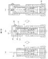
- Embodiment 1 1A to 1C show the structure and operating procedure of a three-component mixing container.
- FIG. 1D shows details of some of the diagrams of FIG. 1A.
- the main body A (2) and the main body B (3) have an in-row structure, and can be slid in the axial direction (dashed line in the figure).
- FIG. 1D shows an ⁇ view and a ⁇ - ⁇ cross section in (a) of FIG. 1A.
- the stopper 13 is provided on the side surface of the main body B (3), and is fitted into and fixed to the hole 12 provided in the main body A (2).
- the hole portion 12 has a notch portion 7, and the notch portion 7 reduces the rigidity around the hole portion 12 of the main body A (2), so that the stopper 13 is attached to the hole portion 12. It is easy to insert.
- the hole 12 is composed of an upper positioning hole 8, a middle positioning hole 9, and a lower positioning hole 10.
- the width of each hole end is small, and the stopper 13 passes through each hole end. When doing, it receives resistance and moves. This resistance prevents unintentional movement from one positioning hole to another positioning hole, and the stopper 13 has the above three positions (upper position, middle position, lower position). (Position).
- there is an opening 11 in the ⁇ - ⁇ cross section there is an opening 11 in the ⁇ - ⁇ cross section, and the sample that has entered from above the mixing container passes through this opening 11 and flows downward in the mixing container.
- FIG. 1A (a) when the main body B (3) is moved to the above-described upper positioning hole 8 and the sample 1 (4) is poured from the main body B (3), the sample 1 (4) becomes an arrow in the figure. As shown by the solid line with the mark, the sample 1 (4) is accumulated in the space formed by the bottom 1 and the main body A (2) through each opening. After the sample 1 (4) is poured into the required amount, as shown in FIG. 1A (b), the main body B (3) is moved to the middle positioning hole 9, and the sample 1 (4) is inserted. Block the opening entrance of the space. In this state, when the sample 2 (5) is poured from the main body B (3), it accumulates in a space formed by the main body A (2) and the main body B (3).
- FIG. 1B (a) when a required amount of sample 3 (6) is dispensed into the main body B (3), it collects in the space formed by the main body A (2) and the main body B (3). Thereafter, as shown in FIG. 1B (b), the cap portion 14 is screwed into the main body B (3) to close the space formed by the main body A (2) and the main body B (3). In this state, as shown in FIG. 1B (c), when the main body B (3) is slid to the upper position, the sample 2 (5) and the sample 3 (6) are collected, and the sample 1 (4) is accumulated. The sample 20 is obtained by mixing the three samples.
- FIG. 1C (a) when the mixing container 33 is turned upside down, the mixed sample 20 flows into the main body B (3).
- FIG. 1C (b) when the cap 17 of the cap portion 14 is opened and the bottom 1 is pushed in the direction of the arrow, a part 21 of the mixed sample 20 is poured into the spout 18 of the cap portion 14. Extruded from.
- the bottom 1 comes out of a flexible material (for example, silicon rubber) that can be deformed, and as shown in FIG. 1C (b), the bottom 1 is pushed in the direction of the arrow, thereby mixing the container. Since it is recessed inside 33, the gas in the mixing container is compressed, and the mixed sample 20 can be discharged from the spout 18.
- a flexible material for example, silicon rubber
- the main bodies A and B constituting the mixing container 33 described above are materials that satisfy chemical resistance, particularly strong resistance to strong alkaline aqueous solution, excellent moldability, and the like, and are inexpensive materials. Is required. Therefore, PP (polypropylene) is used in the present embodiment.
- the main bodies A and B are each formed by injection molding. Assemble body B into body A by press fitting.
- the size of the mixing container 33 is preferably a palm size. The reason is that the mixing container 33 is held and operated. If it is too large, the amount of liquid to be mixed increases, and it becomes necessary to prepare a larger amount than the desired mixing amount. This is because the amount to be used increases and waste occurs.
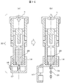
- FIG. 2 is a view showing a lock mechanism for preventing sample leakage.
- the main body A (2) and the main body B (3) do not slide because the catch portion 25 of the main body A (2) is engaged with the convex portion 24 of the main body B (3). It is locked to.
- FIG. 2 (b) when the cap portion 14 is screwed into the main body A (2), the wedge portion 23 of the cap portion 14 becomes the hook portion 25 and the main body B of the main body A (2). (3) bite into the convex part 24, the hook part 25 of the main body A (2) comes off from the convex part 24 of the main body B (3), and the lock is released.
- the lock is released, as shown in FIG. 2C, the main body B (3) can be slid to the upper position, and the sample 2 (5) and the sample 3 (6) become the sample 1. (4)
- the sample 20 which flows into the side and mixed is made.
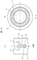
- FIG. 3 is a diagram showing a scale for adjusting the amount of the sample.
- (A) is sectional drawing of a mixing container,
- (b) shows the figure which expanded the scale when it sees from (gamma) position shown by (a). It is the figure which showed the scale 27 for adjusting the quantity which puts the sample 3 (6) into the main body B (3).
- the main body B (3) is made of a transparent material, and the sample 3 (6) can be confirmed from the outside of the main body B (3).
- the main body B (3) is provided with a scale 27 as shown by an arrow ⁇ in FIG. 3, and the amount of the sample 3 (6) poured can be adjusted according to the scale.
- the scale 27 may be easily understood by changing the color.
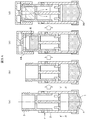
- FIG. 4 is a diagram showing the jig 28 when the mixing container 33 is used.
- the main body A (2) is inserted into the groove of the jig 28 with the error portion 29 provided on the main body A (2), thereby allowing the container 33 to stand up.
- the jig 28 is fixed to the floor surface and can be held so as not to move even if force is applied to the container 33. By doing so, the cap portion 14 can be screwed into the main body B (3) without having the main body A (2) or the main body B (3).
- the mixing container shown in Embodiment 1 has a structure capable of mixing three liquids, but two liquids can also be mixed. Since the mixed liquid is usually sufficient if two or three liquids can be mixed, the mixing container having this structure is versatile.
- Embodiment 2 >> 5A and 5B are structural diagrams and operation flows of another embodiment of the present invention.
- the main structural differences from FIGS. 1A to 1D shown in Embodiment 1 are that the space for inserting the sample 2 (5) is omitted, and the two samples of only the sample 1 (4) and the sample 3 (6) are omitted. Is to be mixed. Further, as shown in the ⁇ view of FIG. 5B, since only two samples are mixed, the stopper 13 only needs to be located at two positions, the upper positioning hole 8 and the lower positioning hole 10.
- the body B (3) is slid to the lower position to close the space in which the sample 1 (4) is placed.
- the sample 1 (4) is held in the container 33.
- the sample 3 (6) is poured into the space formed by the main body B (3) and the main body A (2), and the cap portion 14 is screwed into the main body A (2). The space containing the sample 3 (6) is closed.
- the mixing container shown in Embodiment 2 is characterized by a simple structure, and has an advantage in terms of manufacturing cost. Therefore, when mixing two liquids, the container of this structure can be used. Although omitted in FIG. 5A, a lock mechanism for preventing sample leakage similar to FIG. 2 may be provided.
- FIG. 6 is a diagram showing an outline of the entire apparatus system using the mixing container 33 of the present invention.
- a part 21 of the sample mixed from the mixing container 33 is put into a sample cup 35 fixed to a tray 34 provided with a hole 31.
- the measurement container 39 is lowered with respect to the sample cup 35, and the holding arm 37 is hooked on the protruding portion of the sample cup 35 and held.
- the measurement container 39 is provided with a handle 38 for facilitating holding and a nozzle 36 for introducing vaporized gas generated from the sample in the sample bottle 35 into the analyzer 40. Although not shown, the nozzle 36 and the sample cup 35 are connected inside the measurement container 39.
- the measurement container 39 is set in the sample introduction unit 42 of the analyzer 40. After the setting, the sample gas vaporized in the sample cup 35 is introduced into the analyzer 40 and the components of the part 22 of the mixed sample are analyzed, and the analysis result is displayed on the operation panel 41.
- this invention is not limited to an above-described Example, Various modifications are included.
Landscapes
- Health & Medical Sciences (AREA)
- Chemical & Material Sciences (AREA)
- Analytical Chemistry (AREA)
- General Health & Medical Sciences (AREA)
- Hematology (AREA)
- Clinical Laboratory Science (AREA)
- Chemical Kinetics & Catalysis (AREA)
- Physics & Mathematics (AREA)
- Life Sciences & Earth Sciences (AREA)
- Biochemistry (AREA)
- General Physics & Mathematics (AREA)
- Immunology (AREA)
- Pathology (AREA)
- Package Specialized In Special Use (AREA)
Abstract
La présente invention concerne une cuve avec laquelle il est possible de mélanger au moins deux sortes d'échantillons liquides, en poudre ou granulaires, de manière sûre, aisée, rapide et fiable sans contamination, puis de retirer facilement l'échantillon mélangé. La cuve de mélange est caractérisée en ce qu'elle est formée d'au moins deux parties, en ce qu'elle comporte des espaces dans au moins deux chambres servant à stocker les au moins deux sortes d'échantillons, et en ce que deux parties sont configurées de façon à pouvoir coulisser en direction axiale et à pouvoir adopter, suite à un changement de la position relative des deux parties, un état dans lequel les au moins deux sortes de différents échantillons sont stockés séparément, et un état dans lequel les au moins deux sortes de différents échantillons qui ont été stockés sont mélangés.
Priority Applications (1)
| Application Number | Priority Date | Filing Date | Title |
|---|---|---|---|
| JP2015522774A JPWO2014203761A1 (ja) | 2013-06-20 | 2014-06-10 | 混合容器及びそれを用いた分析装置 |
Applications Claiming Priority (2)
| Application Number | Priority Date | Filing Date | Title |
|---|---|---|---|
| JP2013-129821 | 2013-06-20 | ||
| JP2013129821 | 2013-06-20 |
Publications (1)
| Publication Number | Publication Date |
|---|---|
| WO2014203761A1 true WO2014203761A1 (fr) | 2014-12-24 |
Family
ID=52104499
Family Applications (1)
| Application Number | Title | Priority Date | Filing Date |
|---|---|---|---|
| PCT/JP2014/065281 Ceased WO2014203761A1 (fr) | 2013-06-20 | 2014-06-10 | Cuve de mélange, et dispositif d'analyse utilisant ladite cuve |
Country Status (2)
| Country | Link |
|---|---|
| JP (1) | JPWO2014203761A1 (fr) |
| WO (1) | WO2014203761A1 (fr) |
Cited By (2)
| Publication number | Priority date | Publication date | Assignee | Title |
|---|---|---|---|---|
| CN105842041A (zh) * | 2016-05-11 | 2016-08-10 | 张兆军 | 粮仓分样器 |
| CN116965400A (zh) * | 2023-07-18 | 2023-10-31 | 深圳市保安医疗用品有限公司 | 一种用于处理生物样品的装置 |
Citations (3)
| Publication number | Priority date | Publication date | Assignee | Title |
|---|---|---|---|---|
| JPH0465775U (fr) * | 1990-10-18 | 1992-06-09 | ||
| JPH08500314A (ja) * | 1992-08-20 | 1996-01-16 | ロレアル | 内容物を貯蔵し混合するための多重区画分配器 |
| JP2010023890A (ja) * | 2008-07-22 | 2010-02-04 | Taisei Kako Co Ltd | 二物質混合容器 |
-
2014
- 2014-06-10 JP JP2015522774A patent/JPWO2014203761A1/ja active Pending
- 2014-06-10 WO PCT/JP2014/065281 patent/WO2014203761A1/fr not_active Ceased
Patent Citations (3)
| Publication number | Priority date | Publication date | Assignee | Title |
|---|---|---|---|---|
| JPH0465775U (fr) * | 1990-10-18 | 1992-06-09 | ||
| JPH08500314A (ja) * | 1992-08-20 | 1996-01-16 | ロレアル | 内容物を貯蔵し混合するための多重区画分配器 |
| JP2010023890A (ja) * | 2008-07-22 | 2010-02-04 | Taisei Kako Co Ltd | 二物質混合容器 |
Cited By (2)
| Publication number | Priority date | Publication date | Assignee | Title |
|---|---|---|---|---|
| CN105842041A (zh) * | 2016-05-11 | 2016-08-10 | 张兆军 | 粮仓分样器 |
| CN116965400A (zh) * | 2023-07-18 | 2023-10-31 | 深圳市保安医疗用品有限公司 | 一种用于处理生物样品的装置 |
Also Published As
| Publication number | Publication date |
|---|---|
| JPWO2014203761A1 (ja) | 2017-02-23 |
Similar Documents
| Publication | Publication Date | Title |
|---|---|---|
| CN104135945B (zh) | 一种样品提取、稀释和排放装置 | |
| EP2194385B1 (fr) | Conteneur de réactif | |
| CN101848767B (zh) | 存储生物样本的容器及存储生物样本的方法 | |
| US12490960B2 (en) | Device and method for taking up and handling a liquid sample and a substance | |
| KR20120009424A (ko) | 용시 혼합 용기 | |
| US20140313850A1 (en) | Container for mixing two different types of solutions | |
| JP2008006431A (ja) | 平衡化装置 | |
| US7554658B2 (en) | Cuvette and cuvette cap | |
| CN105947388A (zh) | 用于瓶罩器的柱体活塞装置 | |
| KR101934819B1 (ko) | 검체 용기 | |
| WO2014203761A1 (fr) | Cuve de mélange, et dispositif d'analyse utilisant ladite cuve | |
| CA2749777C (fr) | Dispositif de fermeture pour contenant de reactif | |
| KR101800448B1 (ko) | 샘플 수용 장치 | |
| KR20160073929A (ko) | 혼합 용기 | |
| US7681762B2 (en) | Device for storing and dispensing fluid substances | |
| JP4351577B2 (ja) | 試薬容器 | |
| KR101934186B1 (ko) | 시료 보관 및 이송이 가능한 시료 컵 | |
| US20210086184A1 (en) | Container and method for activating reagents in such a container | |
| US20020185497A1 (en) | Sampling port system | |
| JP5154172B2 (ja) | 二剤混合容器 | |
| US20110076206A1 (en) | Reagent containers for compact test devices | |
| JP2003300547A (ja) | 流体用容器 | |
| CN217006953U (zh) | 一种样品检测装置 | |
| JP2004061470A (ja) | 自動注出が可能な液体収容容器 | |
| JP2026064380A (ja) | 液体吐出装置 |
Legal Events
| Date | Code | Title | Description |
|---|---|---|---|
| 121 | Ep: the epo has been informed by wipo that ep was designated in this application |
Ref document number: 14813712 Country of ref document: EP Kind code of ref document: A1 |
|
| ENP | Entry into the national phase |
Ref document number: 2015522774 Country of ref document: JP Kind code of ref document: A |
|
| NENP | Non-entry into the national phase |
Ref country code: DE |
|
| 122 | Ep: pct application non-entry in european phase |
Ref document number: 14813712 Country of ref document: EP Kind code of ref document: A1 |